Table of Contents
Advertisement
Quick Links
Extron Electronics, USA
Extron Electronics, Europe
1230 South Lewis Street
Beeldschermweg 6C
Anaheim, CA 92805
3821 AH Amersfoort
USA
The Netherlands
714.491.1500
+31.33.453.4040
www.extron.com
Fax 714.491.1517
Fax +31.33.453.4050
© 2006 Extron Electronics. All rights reserved.
Extron Electronics, Asia
Extron Electronics, Japan
135 Joo Seng Road, #04-01
Kyodo Building
PM Industrial Building
16 Ichibancho
Singapore 368363
Chiyoda-ku, Tokyo 102-0082 Japan
+65.6383.4400
+81.3.3511.7655
Fax +65.6383.4664
Fax +81.3.3511.7656
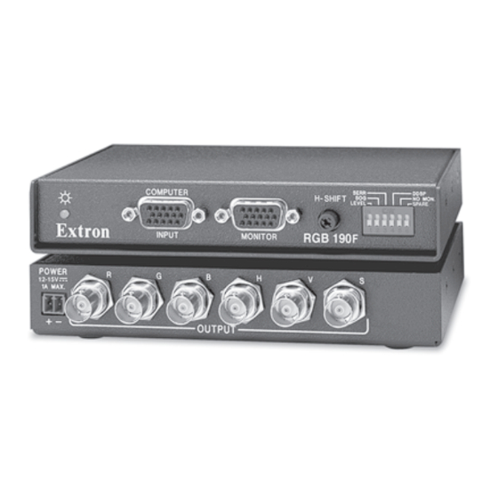
User's Manual
Analog Computer-Video Interface
RGB 190F
RGB 192
RGB 198
68-647-01 Rev. D
05 06
Advertisement
Table of Contents

Related Manuals for Extron electronics RGB 190FM


Summary of Contents for Extron electronics RGB 190FM
- Page 1 Extron Electronics, USA Extron Electronics, Europe Extron Electronics, Asia 1230 South Lewis Street Beeldschermweg 6C 135 Joo Seng Road, #04-01 Anaheim, CA 92805 3821 AH Amersfoort PM Industrial Building The Netherlands Singapore 368363 714.491.1500 +31.33.453.4040 +65.6383.4400 www.extron.com Fax 714.491.1517 Fax +31.33.453.4050 Fax +65.6383.4664 ©...
-
Page 2: Fcc Class A Notice
Precautions Safety Instructions • English Warning This symbol is intended to alert the user of important Power sources • This equipment should be operated only from the power source indicated on the product. This equipment is intended to be used with a main operating and maintenance (servicing) instructions power system with a grounded (neutral) conductor. -
Page 4: Table Of Contents
Table of Contents Chapter 1 • Introduction ... 1-1 About this Manual ... 1-2 About the RGB 190F, RGB 192, and RGB 198 Features ... 1-3 Chapter 2 • Installation and Operation Installation Overview ... 2-2 Mounting the Interfaces ... 2-2 Tabletop placement ... -
Page 5: Chapter 1 • Introduction
Each RGB interface has two or more model options: Three RGB 190F models • RGB 190FV for PC computers • RGB 190FM for Macintosh computers • RGB 190FS for SGI computers Two RGB 192 models • RGB 192V for PC computers •... -
Page 6: Chapter 2 • Installation And Operation
Introduction, cont’d RGBHV, RGBS, or RGsB outputs — Select the output format via cabling setup and front panel DIP switch. Serration pulse switch — This DIP switch-selectable feature adds or strips the serration pulses from the output signal to make it compatible with digital display devices. Use the serration pulse switch if flagging or bending occurs at the top of the video display. -
Page 7: Installation Overview
Installation and Operation Installation and Operation, cont’d Installation Overview This is an overview of the installation process. You will find detailed installation and operation instructions in this chapter. Install and set up the RGB 190F, RGB 192, or RGB 198 interfaces by following these basic steps: Turn off all of the equipment (computers, remote controls, interface, projector/monitor, local monitor and speakers... -
Page 8: Rack Mounting (Rgb 198 Only)
Installation and Operation, cont’d Hold the interface with attached brackets against the underside of the desk/table. With a soft pencil mark the location of holes for screws on the desk based on the following: For the RGB 190 and RGB 192, mark the opening approximately 1.0"... - Page 9 Installation and Operation, cont’d RGB 198 UNIVERSAL INTERFACE C O M P U T E R S E R R D D S P M O N I TO R H - S H I F T S O G N O M O N .
- Page 10 Installation and Operation, cont’d 4 — DDSP DDSP disables all sync processing. This feature may be necessary for digital display devices such as LCD, DLP (digital light processor) and plasma displays. Use this option if the image is not displayed properly after other options, such as serration pulse and video termination changes, have been tried.
-
Page 11: Operation And Troubleshooting
Installation and Operation, cont’d CAUTION Wiring the audio incorrectly can damage the audio output circuits. Connect the sleeve(s) to ground (GND). Connecting the sleeve(s) to a negative (-) terminal will damage audio output circuits. See caution Ring Sleeve (s) Sleeve Ring See caution Unbalanced Output... -
Page 12: Reference Information
Installation and Operation, cont’d RGB 190F, RGB 192, and 198 A ppendix A Reference Information Specifications Included Parts Optional Accessories Cables RGB 190F, RGB 192, and RGB 198 • Installation and Operation 2-12... - Page 13 Reference Information Reference Information, cont’d Specifications Video Gain ... Unity (0.7 V), (0.8 V) 15% with 3 dB peaking Bandwidth ... 300 MHz (-3 dB) Max. rise/fall time ... 1.5 ns Video input and loop-through Number/signal type ... 1 analog VGA–UXGA, Mac, Sun RGBHV, RGBS, RGsB 1 buffered local monitor loop-through identical to the input...
- Page 14 Unless otherwise noted, these items are included in each order for an RGB 190F, RGB 192, or RGB 198: Interface RGB 190FV VGA M 6’ MHR (Molded) RGB 190FM Mac Adapter 15-HDM Kit with audio RGB 190FS 13W3 Adapter 15-HDM Kit with audio RGB 192V VGAM 6’...
-
Page 15: Included Items
Reference Information, cont’d Included items Rubber feet IEC power cord Tweeker Universal 12VDC external power supply (RGB 190 and RGB 192 only) Under-desk mounting kit instruction card 3.5 mm, 5-pole captive screw connector Under-desk mounting bracket kit 3/32 Hex wrench (RGB 198 only) MAAP single blank (black) (RGB 198 only) - Page 16 Reference Information, cont’d RGB 190F, RGB 192, and RGB 198 • Reference Information...
Need help?
Do you have a question about the RGB 190FM and is the answer not in the manual?
Questions and answers