Table of Contents
Advertisement
Quick Links
Advertisement
Table of Contents

Related Manuals for Advantech ARK-3399


Summary of Contents for Advantech ARK-3399
- Page 1 User Manual ARK-3399 Compact Embedded Computer...
- Page 2 The documentation and the software included with this product are copyrighted 2008 by Advantech Co., Ltd. All rights are reserved. Advantech Co., Ltd. reserves the right to make improvements in the products described in this manual at any time without notice.
-
Page 3: Declaration Of Conformity
Because of Advantech’s high quality-control standards and rigorous testing, most of our customers never need to use our repair service. If an Advantech product is defec- tive, it will be repaired or replaced at no charge during the warranty period. For out- of-warranty repairs, you will be billed according to the cost of replacement materials, service time and freight. -
Page 4: Packing List
Technical Support and Assistance Visit the Advantech web site at www.advantech.com/support where you can find the latest information about the product. Contact your distributor, sales representative, or Advantech's customer service center for technical support if you need additional assistance. Please have the following information ready before you call: –... -
Page 5: Table Of Contents
......1 Introduction ....................2 Product Feature ..................2 Chipset ...................... 3 1.3.1 Functional Specification ..............3 Mechanical Specification................5 Figure 1.1 ARK-3399 Dimensions ..........5 1.4.1 Dimension ..................5 1.4.2 Weight................... 5 Electrical Specification ................6 1.5.1 Power supply Voltage ..............6 1.5.2... - Page 6 Figure 4.5 Unscrew the ground wire of LVDS cable and discon- nect all the cables and boards........42 Figure 4.6 Unscrew the boards’ screws and hex-bolts for disas- sembly ..............42 Figure 4.7 Unscrew the power module screws on the bottom to disassemble the power module........ 43 ARK-3399 User Manual...
-
Page 7: Chapter 1 General Introduction
Chapter General Introduction This chapter gives background information on ARK-3399 series. -
Page 8: Introduction
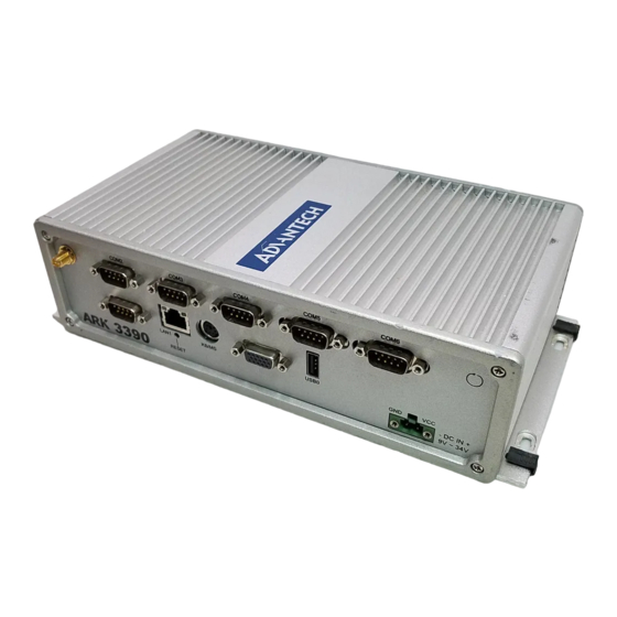
The ARK-3399 answers this demand by offering 1 x VGA and 1 x LVDS interface for dual display, 5 x USB 2.0 ports,1 x Giga LAN port and 2 x COM ports; packed into a small rugged unit and powered by an Intel Core Duo processor. -
Page 9: Chipset
Supports several optional sections of Serial ATA II: Extensions to SATA & IDE Serial ATA 1.0 Specification, Revision 1.0 Interface Supports SATA transfers to 300 Mbytes/sec. Supports Compact Flash Card Type II Socket CF Socket on board: CF Type II 50P 90D(M) external connector x 1 ARK-3399 User Manual... - Page 10 Ear Phone Jack LVDS Codec: Chrontel CH7308B Supports 2-CH 24-bit LVDS output up to 1280*1024 48bit LVDS LVDS Connector on board: 3M MDR 26P 90D(F) x 1 Battery support: CR2032 Battery backup BATTERY 3V/210 mAh with WIRE x 1 ARK-3399 User Manual...
-
Page 11: Mechanical Specification
Mechanical Specification 252.5 264.50 (3.5) R2.5 Section B-B Detailed "A" SCALE 4 :1 Figure 1.1 ARK-3399 Dimensions 1.4.1 Dimension 264.5[10.41] x 69.2[2.72] x 137.25[5.4] Unit: mm[Inch] 1.4.2 Weight 2.0 kg (4.4 lb) ARK-3399 User Manual... -
Page 12: Electrical Specification
5~500 Hz, 1 Oct/min., 1hr/axis, x,y,z 3 axes. 1.6.4 Shock during operation When system is equipped with Compact Flash card only: 50G, IEC 60068-2-27, half sine, 11 ms duration. When system is equipped with 2.5-inch: 20G, IEC 60068-2-27, half sine, 11 ms duration. ARK-3399 User Manual... -
Page 13: Chapter 2 H/W Installation
Chapter H/W installation This chapter explains the setup procedures of the ARK-3399 hard- ware. -
Page 14: Introduction
2.2.1 Jumper description You may configure the ARK-3399 to match the needs of your application by setting jumpers. A jumper is a metal bridge used to close an electric circuit. It consists of two metal pins and a small metal clip (often protected by a plastic cover) that slides over the pins to connect them. -
Page 15: Jumper And Connector Location
2.2.2 Jumper and Connector Location Figure 2.1 ARK-3399 jumper location 2.2.3 Jumper List 1. Clear CMOS Jumper ( J1 ) Close Function Normal* Clear (*): means default setting of the jumper/function. 2. LVDS Voltage Selector Jumper ( J2 ) Close pins Function 3.3 V*... -
Page 16: Jumper Settings
2.2.4 Jumper Settings 1. CMOS Jumper ( J1 ) ARK-3399 series of embedded box computer provide a jumper - J1 located on the internal board for selecting the CMOS of Clear or Normal status. Close pins Function Normal* Clear (*): means default setting of the jumper/function. -
Page 17: Connectors
2.3.1.1 COM Connectors ARK-3399 provides two D-sub 9-pin connectors, which offer one standard RS-232 and one RS-232/422/485 serial communication interface ports each as COM1 and COM2. The default setting of COM2 is RS-232, if you want to use RS-422/485, Two things have to be done. -
Page 18: Table 2.1: Com Standard Serial Port Pin Assignments
2.3.1.2 Ethernet Connector (LAN) ARK-3399 is equipped with an Intel 82541PI Ethernet controller that is fully compliant with IEEE 802.3u 10/100/1000Base-T CSMA/CD standards. The Ethernet port pro- vides a standard RJ-45 jack connector with LED indicators on the front side to show its Active/Link status (Green LED) and Speed status (Yellow LED). -
Page 19: Figure 2.5 Ps/2 Connector
The ARK-3399 provides a PS/2 keyboard/mouse connector. A 6-pin mini-DIN con- nector is located on the rear metal face plate of the ARK3399. The ARK-3399 comes with an adapter to convert from the 6-pin mini-DIN connector to two 6-pin mini-DIN connectors for PS/2 keyboard and PS/2 mouse connection. -
Page 20: Figure 2.7 Usb0 Connector
2.3.1.5 USB Connector ARK-3399 provides 5 connectors of USB interface, which give complete Plug & Play and hot swapping for up to 127 external devices. The USB interface complies with USB UHCI, Rev. 2.0 compliant. The USB interface can be disabled in the system BIOS setup. -
Page 21: Table 2.7: Line-In Connector
Re-start Interval Time must be at least 3 seconds. 2.3.1.8 LED Indicators There are two LEDs on ARK-3399 front metal face plate for indicating system status: PWR LED is for power status; and HDD LED is for HDD & compact flash disk active status. -
Page 22: Figure 2.11Lvds Connector
2.3.1.11 LVDS Connector The ARK-3399 comes with a D-Sub 26-pin connector that carries LVDS signal out- put, and can direct connect to LVDS LCD Display via external cable. The system also provide a jumper of J2 on internal motherboard for selecting the LCD signal power of 5V or 3.3V, please refer to the jumper table of J2, and “Full Dis-... -
Page 23: Installation
Table 2.12: LCD Backlight Connector Pin Assignment Signal name +12 V BKLTEN +5 V LVDS_DCLK LVDS_DDAT Reserved Reserved Installation 2.4.1 HDD Installation Unscrew the HDD door screws. Figure 2.13 Unscrew the HDD door screws ARK-3399 User Manual... -
Page 24: Figure 2.14Assemble Hdd And Hdd Frame By 4 Screws
Figure 2.14 Assemble HDD and HDD frame by 4 Screws Screw on the HDD damper screws to assemble the HDD door and HDD frame. Figure 2.15 Screw on the HDD damper screws to assemble the HDD door and HDD frame ARK-3399 User Manual... -
Page 25: Figure 2.16Connect The Hdd Cables
Install the memory module into the SO-DIMM socket at the bottom of the Main board. Figure 2.17 Install the memory module into the SO-DIMM socket at the bottom of the Main board Reverse the 2.4.1-1 to cover back the HDD door. ARK-3399 User Manual... -
Page 26: Cf Card Installation
Install the CF card into the CF slot at the bottom of the Main board. Figure 2.18 Install the CF card into the CF slot at the bottom of the Main board Reverse the 2.4.1-1 to cover back the HDD door. ARK-3399 User Manual... -
Page 27: Bios Operation
Chapter BIOS Operation This chapter describes how to set BIOS configuration data. -
Page 28: Bios Introduction
CPUs from 386 through Pentium and AMD Geode, K7 and K8 (including multiple pro- cessor platforms), and VIA Eden C3 and C7 CPU. You can use Advantechís utilities to select and install features to suit your designs for customers need. -
Page 29: Main Menu
This setup page includes Load system optimized value, and the system would be in best performance configuration. Set Password Establish, change or disable password. Save & Exit Setup Save CMOS value settings to CMOS and exit BIOS setup. Exit Without Saving Abandon all CMOS value changes and exit BIOS setup. ARK-3399 User Manual... -
Page 30: Standard Cmos Features
The system boot will not stop for a keyboard error; it will stop for all other errors. (Default value) All, But Diskette The system boot will not stop for a disk error; it will stop for all other errors. ARK-3399 User Manual... -
Page 31: Advanced Bios Features
Select boot device priority by Floppy. LS120 Select boot device priority by LS120. Hard Disk Select boot device priority by Hard Disk. CDROM Select boot device priority by CDROM. Select boot device priority by ZIP. USB-FDD Select boot device priority by USB-FDD. ARK-3399 User Manual... - Page 32 MPS Version Control for OS [1.4] This item sets the operating system multiprocessor support version. OS Select For DRAM > 64M [Non-OS2] Select OS2 only if system is running OS/2 operation system with greater than 64MB of RAM on the system. ARK-3399 User Manual...
-
Page 33: Advanced Chipset Features
PEG/Onchip VGA Control [Onchip VGA] This item is setting for start up Video output from Add-on-Card or Onboard device. On-Chip Frame Buffer Size [8MB] The default setting is 8MB. The options available include 1 MB and 8 MB. ARK-3399 User Manual... - Page 34 Panel Type [640X480, 18bits] These fields allow you to select the LCD Panel type. The default values for these ports are: 640 x 480, 18bits 800 x 600 18bits 1024 x 768 18bits 1280 x 1024 48bits ARK-3399 User Manual...
-
Page 35: Integrated Peripherals
If enable, the flow control will force signal to the desired polarity under the empty or not empty condition. Watch Dog Timer-Out Value Unit[Minutes] This item allows user to select watch dog time of value unit with minutes or seconds. ARK-3399 User Manual... -
Page 36: Power Management Setup
V/H SYNC+BlankThis option will cause system to turn off vertical and horizontal synchronization ports and write blanks to the video buffer. Blank Screen This option only writes blanks to the video buffer. DPMS Initial display power management signaling. ARK-3399 User Manual... - Page 37 This item allows user to enable and key in Date/time to power on system Disabled Disable this function. Enabled Enable alarm function to power on system Data (of month) Alarm1-31 Resume Time (HH:MM:SS)Alarm (0-23) : (0-59) : 0-59) ARK-3399 User Manual...
-
Page 38: Pnp/Pci Configurations
This BIOS feature determines the maximum TLP (Transaction Layer Packet) payload size that can be supported by the motherboard chipset's PCI Express controller. The TLP payload size determines the amount of data transmitted within each data packet. ARK-3399 User Manual... -
Page 39: Pc Health Status
This “PC Health Status” option controls the Thermal, FAN and Voltage status of the board. this page is developed by Chipset independent. Shutdown Temperature [Disabled] This item enables users to set the limitation of CPU temperature, the range is from 85°C through 100°C. 3.2.9 Frequency/Voltage Control ARK-3399 User Manual... -
Page 40: Load Optimized Defaults
Load Optimized Defaults loads the default system values directly from ROM. If the stored record created by the Setup program should ever become corrupted (and therefore unusable). These defaults will load automatically when you turn the system on. ARK-3399 User Manual... -
Page 41: Set Password
Select Set Password again, and at the ìEnter Passwordî prompt, enter the new password and press <Enter>. At the ”Confirm Password” prompt, retype the new password, and press <Enter>. Select Save to CMOS and EXIT, type <Y>, then <Enter>. ARK-3399 User Manual... -
Page 42: Save & Exit Setup
Select Save to CMOS and EXIT, type <Y>, then <Enter>. 3.2.12 Save & Exit Setup Note! Type “Y” will quit the BIOS Setup Utility and save user setup value to CMOS. Type “N” will return to BIOS Setup Utility. ARK-3399 User Manual... -
Page 43: Quit Without Saving
3.2.13 Quit Without Saving Note! Type “Y” will quit the BIOS Setup Utility without saving to CMOS. Type “N” will return to BIOS Setup Utility. ARK-3399 User Manual... - Page 44 ARK-3399 User Manual...
-
Page 45: Full Disassembly Procedure
Chapter Full Disassembly Procedure This chapter introduce how to dis- assembly the system. -
Page 46: Introduction
Users should be aware that Advantech Co., Ltd. takes no responsibility Whatsoever for any problems or damage caused by user disassembly of the ARK- 3399. Make sure the power cord of the ARK-3399 is unplugged before you start dis- assembly. - Page 47 Unscrew the panel screws. Figure 4.3 Unscrew the panel screws Unscrew the hex-bolts on the panel. Figure 4.4 Unscrew the hex-bolts on the panel Repeat the instruction 4.2~4.5 to disassemble the opposite panel. Remove the top cover. ARK-3399 User Manual...
- Page 48 Unscrew the ground wire of LVDS cable and disconnect all the cables and boards. Figure 4.5 Unscrew the ground wire of LVDS cable and disconnect all the cables and boards Unscrew the boards’ screws and hex-bolts for disassembly. Figure 4.6 Unscrew the boards’ screws and hex-bolts for disassembly ARK-3399 User Manual...
-
Page 49: Figure 4.7 Unscrew The Power Module Screws On The Bottom To Disassemble The Power Module
Unscrew the power module screws on the bottom to disassemble the power module. Figure 4.7 Unscrew the power module screws on the bottom to disassemble the power module ARK-3399 User Manual... - Page 50 No part of this publication may be reproduced in any form or by any means, electronic, photocopying, recording or otherwise, without prior written permis- sion of the publisher. All brand and product names are trademarks or registered trademarks of their respective companies. © Advantech Co., Ltd. 2008...
Need help?
Do you have a question about the ARK-3399 and is the answer not in the manual?
Questions and answers