Table of Contents
Advertisement
Quick Links
Advertisement
Table of Contents

Related Manuals for Advantech ARK-3534


Summary of Contents for Advantech ARK-3534
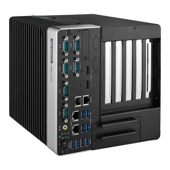
- Page 1 User Manual ARK-3534 Fanless Embedded Box PC...
- Page 2 This package contains a hard-copy user manual in Chinese for China CCC certifica- tion purposes. There is an English user manual included as a PDF file on the CD. Please disregard the Chinese hard copy user manual if the product is not to be sold and/or installed in China. ARK-3534 User Manual...
- Page 3 The documentation and the software included with this product are copyrighted 2023 by Advantech Co., Ltd. All rights are reserved. Advantech Co., Ltd. reserves the right to make improvements in the products described in this manual at any time without notice.
- Page 4 Because of Advantech’s high quality-control standards and rigorous testing, most of our customers never need to use our repair service. If an Advantech product is defec- tive, it will be repaired or replaced at no charge during the warranty period. For out- of-warranty repairs, you will be billed according to the cost of replacement materials, service time and freight.
- Page 5 Technical Support and Assistance Visit the Advantech website at www.advantech.com/support where you can find the latest information about the product. Contact your distributor, sales representative, or Advantech's customer service center for technical support if you need additional assistance. Please have the following information ready before you call: –...
- Page 6 Power cable 3-pin 183 cm (6 ft), USA type 1702002605 Power cable 3-pin 183 cm (6 ft), EU type 1702031801 Power cable 3-pin 183 cm (6 ft), UK type 1700000237 Power cable 3-Pin 183 cm (6 ft), PSE type ARK-3534 User Manual...
- Page 7 70 dB (A). The equipment should only be installed in -restricted access areas. DISCLAIMER: These instructions are provided according to IEC 704-1 specifi- cations. Advantech disclaims all responsibility for the accuracy of any statements con- tained herein. ARK-3534 User Manual...
- Page 8 This product is intended to be supplied by a UL Listed power supply suitable for use at minimum Tma 50 °C (122 °F) whose output meets PS2 (or LPS), ES1(or SELV) and output is rated: 9-36Vdc, 16.65-4.16A. Please contact Advantech for further information.
- Page 9 L'équipement ne doit être installé que dans une zone d'accès restreint. AVERTISSEMENT: Cet ensemble d'instructions est donné conformément à la norme CEI 704-1. Advantech décline toute responsabilité quant à l'exactitude des déclarations contenues dans ce. Au moyen d'un cordon d'alimentation connecté à une prise de courant avec mise à...
- Page 10 ARK-3534 User Manual...
-
Page 11: Table Of Contents
Jumper Settings ................11 Connectors....................14 2.3.1 ARK-3534 External I/O Locations ..........14 Figure 2.2 ARK-3534 Front and Rear I/O Connector Diagram.. 14 Figure 2.3 COM Connector............14 Table 2.2: COM Connector Pin Assignments......14 Table 2.3: COM Connector Pin Assignments......15 Figure 2.4 Ethernet Connector .......... - Page 12 Save & Exit ................108 3.2.7 MEBx ..................109 Appendix A Watchdog Timer Sample Code ..111 EC Watchdog Timer Sample Code ............112 Appendix B Fixing the LAN Order...... 113 Problem Statement ................114 Addressing the LAN Order..............115 ARK-3534 User Manual...
-
Page 13: Chapter 1 General Introduction
Chapter General Introduction This chapter details background information on the ARK-3534 series. -
Page 14: Introduction
Rugged Multi-Functional Design ARK-3534 adopts an advanced thermal design for its desktop processor solution. All models are fanless, and deliver several unique features. These include wide operat- ing temperatures (-20 ~ 60 °C / -4 ~ 140 °F), diverse expandability options, and struc- tural strengthening. -
Page 15: Product Features
1 x M.2 (B key for NVME, SATA, LTE/5G modules) – 1 x M.2 (E key for Wi-Fi, suggested installation at Advantech manufacturing) – Add-on Card Slot: 3534B for 1 x Slot PCIex4+ 1 x Slot PCIex16, 3534C for 1... -
Page 16: Chipset
1 x EHCI Host Controllers, supporting HighSpeed USB 2.0 ports Supports wake-up from sleep states S3 USB1/2 Maximum 1.9A Power Management Supports ACPI ACPI-defined power states (processor driven C states) ACPI Power Management Timer SMI# generation ARK-3534 User Manual... -
Page 17: Susi 4.0
Watchdog Timer Multi-level WDT Programmable 1-255 sec / min Hardware Monitor CPU Temperature / input Current / input Voltage System Information Running HR / Boot record Two ports of CANBus supported ARK-3534 User Manual... -
Page 18: Mechanical Specifications
Mechanical Specifications 1.4.1 Dimensions ARK-3534B/ARK-3534C (W x H x D) 156 x 204 x 230 mm/6.14 x 8.03 x 9.05 in ARK-3534 User Manual... -
Page 19: Weight
ARK-3534B/ARK-3534C: 5.7 kg (12.5 lb) ARK-3534D: 6.41 kg (14.1 lb) Power Requirements 1.5.1 System power Minimum Power Input: 9 ~ 36VDC Optional Adapter: – 150W @19V/7.89A power adapter (optional) – 230W @ 24V/9.58A power adapter (optional) ARK-3534 User Manual... -
Page 20: Operating Environment Specifications
1.6.2 Relative Humidity 95% @ 40 °C (104 °F) (non-condensing) 1.6.3 Storage Temperature -40 ~ 85 °C (-40 ~ 185 °F) 1.6.4 Safety UL, CB, CCC, BSMI 1.6.5 CE/FCC Class B, CCC, BSMI ARK-3534 User Manual... -
Page 21: Chapter 2 Hardware Configuration
Chapter Hardware Configuration... -
Page 22: Introduction
2.2.1 Jumper Description You may configure ARK-3534 to match the needs of your application by setting jump- ers. A jumper is a metal bridge used to close an electric circuit. It consists of two metal pins and a small metal clip (often protected by a plastic cover) that slides over the pins to connect them. -
Page 23: Jumper Locations
Auto Power On Settings for CN22 CN22 Auto Power On Setting Part Number 1653004101 Footprint HD_4x1P_79_D Description PIN HEADER 4x1P 2.0mm 180D(M) DIP 21N12050 Setting Function (3-4) Auto Power On (1-2) Power Button for Power On (Default) ARK-3534 User Manual... - Page 24 3.8V for 5G module 2.2.4.4 Power saving mode settings for ERP1 ERP1 Power saving mode setting Part Number 1653000014 Footprint HD_2x2P_79 Description PIN HEADER 2x2P 2.00mm 180D(M) SMD 21N22050 Setting Function (3-4) Power saving mode (1-2) Normal operating (Default) ARK-3534 User Manual...
- Page 25 1 = 1 x16 PCI Express* (Default) 2.2.4.6 COM3 RI power settings J1 (AMO-I028) on AMO-I028 card J1 (AMO-I028) RI power setting Part Number 1653003201 Footprint HD_3x2P_79_D Description PIN HEADER 3x2P 2.0mm 180D(M) DIP 21N22050 Setting Function (1-2) Normal (default) (3-4) (5-6) +12V ARK-3534 User Manual...
-
Page 26: Connectors
COM Connector ARK-3534 provides up to 6 D-sub 9-pin connectors, which offers RS-232/422/485 serial communication interface ports. The default setting is RS-232, the mode RS-422/ 485 of ARK-3534 COM3/4/5/6 can be supported via the BIOS settings. COM1/2 sup- ports RS-232. COM3~COM6 ... - Page 27 2.3.1.2 Ethernet Connector (LAN) ARK-3534 is equipped with up to 4 x (LAN3/4 are optional by TPN support) Ethernet controllers that are fully compliant with IEEE 802.3u 10/100/1000 Mbps CSMA/CD standards. These Ethernet ports provide a standard RJ-45 jack connector with LED indicators on the front side that demonstrate its Active/Link status (Green LED) and Speed status (Green/Orange LED).
- Page 28 Table 2.6: DIO Connector Pin Assignment Signal Name Signal Name Port0 D0 Port1 D8 Port0 D1 Port1 D9 Port0 D2 Port1 D10 Port0 D3 Port1 D11 Port0 D4 Port1 D12 Port0 D5 Port1 D13 Port0 D6 Port1 D14 Port0 D7 Port1 D15 ARK-3534 User Manual...
- Page 29 2.3.1.5 Power On/Off Button ARK-3534 has a Power On/Off button with LED indicators on the front side that show “On” (Green LED) and “Off/Suspend” statuses (Orange LED). The Power button sup- ports dual functions: Soft Power - On/Off (Instant off or Delay 4 Seconds then off), and Suspend.
- Page 30 2.3.1.9 USB 3.2 - Gen2 and Gen1 ARK-3534 supports 4 x USB 3.2 (Gen2,10G), 2 x USB 3.2 (Gen1, 5G), and 2 x Inde- pendent USB 3.2 (Gen1, 5G) interfaces. The USB interfaces comply with USB UHCI, Rev. 3.0 standards. Please refer to Table 2.5 for its pin assignments. USB 3.2 Gen1/ 2 connectors contain legacy pins to interface with USB 2.0 devices, and a new set of...
- Page 31 2.3.1.10 Remote Switch Connector ARK-3534 provides the remote switch connector for power on/off with a external cable. From the left to the right are Reset, GND, and Power Switch On. Figure 2.10 Remote Switch Connector 2.3.1.11 Phoenix Terminal Connector ARK-3534 supports one 4-pin Phoenix terminal power input connector. Connect the...
-
Page 32: Installation
Installation 2.4.1 CPU/Memory Installation Unscrew the 4 screws on the top cover, and remove the top cover. ARK-3534 User Manual... -
Page 33: External Hdd/Ssd Installation
External HDD/SSD Installation Unscrew the 2 x screws on the hard drive bay Install HDD/SSD with 4 x screws on the HDD/SSD tray. Push back the hard drive bay into the system and secure it using the same screws. ARK-3534 User Manual... -
Page 34: Mounting Kit Installation
2.4.3 Mounting Kit Installation Take the mounting kit and 4 screws (M3x6L) out of the accessory box. Screw one of the 2 screws (M3x6L) on left and right side and secure the system horizontally. ARK-3534 User Manual... -
Page 35: Module/Minipcie Module/Internal Sim Card Slot Installation
2.4.4 M.2 Module/MiniPCIe Module/Internal SIM Card Slot Installation ARK-3534 User Manual... -
Page 36: Attaching The Thermal Pad
Take the thermal pad from the accessory box. Paste the 30 x 30 x 0.2 mm thermal pad to the CPU (as illustrated above). Paste the 46 x 46 x 1 mm piece to the Copper block (as illustrated below). ARK-3534 User Manual... -
Page 37: Bios Settings
Chapter BIOS Settings... -
Page 38: Introduction
AMIBIOS has been integrated into motherboards for over two decades. With the AMIBIOS Setup program, users can modify BIOS settings and control various sys- tem features. This chapter describes the basic navigation of the ARK-3534 BIOS setup screens. AMI's BIOS ROM has a built-in setup program that allows users to modify the basic system configuration. -
Page 39: Entering The Setup
BIOS supports your CPU. If there is no number assigned to the patch code, please contact an Advantech application engineer to obtain an up-to-date patch code file. This will ensure that your CPU‘s system status is valid. -
Page 40: Advanced Bios Features Setup
3.2.2 Advanced BIOS Features Setup Select the Advanced tab from the ARK-3534 setup screen to enter the Advanced BIOS Setup screen. Users can select any item in the left frame of the screen, such as CPU Configuration, to go to the sub menu for that item. Users can display an Advanced BIOS Setup option by highlighting it using the <Arrow>... - Page 41 Active Performance-Cores Number of cores to enable in each processor package. Active Efficient-cores Enable/Disable Per Core Disable. When Per Core Disable Configuration is enabled, selction of Active Cores and Active Efficient-cores will be disabled. ARK-3534 User Manual...
- Page 42 Configure Total Memory Encryption (TME) to protect DRAM data from physical attacks. Legacy Game Compatibility Mode When enabled, Pressing the scroll lock key will toggle the Efficient-cores between being parked when Scroll Lock LED is on and un-parked when LED is off. ARK-3534 User Manual...
- Page 43 Enable/Disable usage of SMM_DELAYED MSR for MP sync in SMI. – SMM Use Block Indication Enable/Disable usage of SMM_BLOCKED MSR for MP sync in SMI. – SMM Use en-US Indication Enable/Disable usage of SMM_ENABLE MSR for MP sync in SMI ARK-3534 User Manual...
- Page 44 3.2.2.2 Power and Performance – CPU Power Management Control ARK-3534 User Manual...
- Page 45 Boot Performance Select the performance state that the BIOS will set before OS hand-off. Intel® Speedstep™ Allows more than two frequency ranges to be supported. ARK-3534 User Manual...
- Page 46 Power Limit 4 in Milli Watts. Power Limit 4 Lock Power Limit 4 MSR 601h Lock. When enabled PL4 configurations are locked during OS. When disabled PL4 configuration can be changed during OS. C states Enable/Disable CPU Power Management. ARK-3534 User Manual...
- Page 47 Thermal Monitor Enable/Disable Thermal Monitor Interrupt Redirection Mode Selection Interrupt Redirection Mode Select for Logical Interrupts Timed MWAIT Enable/Disable Timed MWAIT Support Energy Performance Gain Enable/disable Energy Performance Gain. ARK-3534 User Manual...
- Page 48 Enable/Disable Power Limit 2 override. – Power Limit 2 Power Limit 2 value in Milli Watts. – Energy Efficient Turbo Enable/Disable Energy Efficient Turbo Feature. This feature will opportunisti- cally lower the turbo frequency to increase efficiency. ARK-3534 User Manual...
- Page 49 125. 0 = AUTO. Uses BIOS VR mailbox command 0x9. – PSYS Offset PSYS Offset defined in 1/1000 increments. Range is 0-63999. For an offset of 25.348, enter 25348. PSYS Uses BIOS VR mailbox command 0x4. ARK-3534 User Manual...
- Page 50 A value of AUTO(0) will use the board ID to determine the board design. Any other value will override the board id logic to provide a custom VR Power Delivery Design value. This is intended primarily for vali- dation. ARK-3534 User Manual...
- Page 51 Enabling this option will help mitigate acoustic noise on certain SKUs when the CPU is in deeper C state – Pre Wake time Set the maximum Pre Wake randomization time in micro ticks. Range is 0- 255. This is for acoustic noise mitigation Dynamic Perodicity Alteration (DPA) tuning. ARK-3534 User Manual...
- Page 52 Set VR GT Slow Slew Rate for Deep Package C State ramp time; Slow slew rate equals to Fast divided by number, the number is 2, 4, 8 to slow down the slew rate to help minimize acoustic noise; divide by 16 is disabled ARK-3534 User Manual...
- Page 53 – VR Config Enable VR Config Enable – PS3 Enable PS3 Enable/Disable. 0 - Disabled, 1 - Enabled.Uses BIOS VR mailbox com- mand 0x3. ARK-3534 User Manual...
- Page 54 – PS4 Enable PS4 Enable/Disable. 0 - Disabled, 1 - Enabled. Uses BIOS VR mailbox com- mand 0x3 – IMON Prefix Sets the offset value as positive or negative. ARK-3534 User Manual...
- Page 55 VR Config Enable – PS3 Enable PS3 Enable/Disable. 0 - Disabled, 1 - Enabled.Uses BIOS VR mailbox com- mand 0x3. – PS4 Enable PS4 Enable/Disable. 0 - Disabled, 1 - Enabled. Uses BIOS VR mailbox com- mand 0x3 ARK-3534 User Manual...
- Page 56 – FIVR Spread Spectrum Enable or Disable the FIVR Spread Spectrum. – RFI Spread Spectrum Set the Spread Spectrum. ARK-3534 User Manual...
- Page 57 – Number of P states Sets the number of custom P-states. At least 2 states must be present. ARK-3534 User Manual...
- Page 58 – Power Limit 3 Override Enable/Disable Power Limit 3 override. – Power Limit 3 Power Limit 3 in Milli Watts. – Power Limit 3 Time Window Power Limit 3 Time Window value in Milli seconds. ARK-3534 User Manual...
- Page 59 Specify the duty cycle in percentage that the CPU is required to maintain over the configured time window. Range is 0-100. – Power Limit 3 Lock Power Limit 3 MSR 615h Lock. When enabled PL3 configurations are locked during OS. When disabled PL3 configuration can be changed during OS. ARK-3534 User Manual...
- Page 60 – CFG Lock Configure MSR 0xE2[15], CFG Lock bit. – Overclocking Lock Enable/Disable Overclocking Lock (BIT 20) in FLEX_RATIO(194) MSR. – RC6 (Render Standby) Check to enable render standby support. ARK-3534 User Manual...
- Page 61 – Maximum GT frequency Maximum GT frequency limited by the user. – Disable Turbo GT frequency Enabled: Disables Turbo GT frequency. Disabled: GT frequency is not lim- ited. 3.2.2.3 PCH-FW Configuration ARK-3534 User Manual...
- Page 62 When Disabled ME will not be unconfigured on RTC Clear. Comms hub support Enables/Disables support for Comms Hub. JHI support Enable/Disable Intel(R) DAL Host Interface Service (JHI) Core BIOS Done Message Enable/Disable Core Bios Done message sent to ME ARK-3534 User Manual...
- Page 63 – Me FW Image Re-Flash Enable/Disable Me FW Image Re-Flash function. – FW Update Enable/Disable ME FW Update function. ARK-3534 User Manual...
- Page 64 – TPM Device Selection Configure TPM device ARK-3534 User Manual...
- Page 65 – FIPS mode select FIPS Mode configuration ARK-3534 User Manual...
- Page 66 – Unique platform ID configuration Configure Unique Platform Id Feature ARK-3534 User Manual...
- Page 67 BIOS Reflash Capability State Change BIOS Reflash Capability State – BIOS Boot to Setup Capability State Change BIOS Boot to Setup Capability State – BIOS Pause Before Booting Capability State Change BIOS Pause Before Booting Capability State ARK-3534 User Manual...
- Page 68 Change BIOS Secure Capability Exposure State to FW. This does not affect SecureBoot as such – vPro TBT Dock Support Enable/Disable vPro TBT Dock Support. Note: for the change to take effect, need to put system into G3 state then resume. ARK-3534 User Manual...
- Page 69 ARB-SVN will be blocked from execution – Set HW-Enforced Anti-Rollback for Current SVN Enable hardware-enforced Anti-Rollback mechanism for current ARB-SVN value. FW with lower ARB-SVN will be blocked from execution. The value will be restored to disable after the command is sent. ARK-3534 User Manual...
- Page 70 When enabled, BIOS will automatically send HECI command to revoke OEM keys. – Invoke OEM Key Revocation A Heci command will be send to revoke OEM key. – Extend CSME Measurement to TPM-PCR Enable/Disable Extend CSME Measurement to TPM-PCR[0] and AMT Con- fig to TPM-PCR[1] ARK-3534 User Manual...
- Page 71 3.2.2.4 ACPI Settings Enable ACPI Auto Configuration Enables or Disables BIOS ACPI Auto Configuration. Enable Hibernation Enables or Disables System’s ability to Hibernate (OS/S4 Sleep State). ARK-3534 User Manual...
- Page 72 ACPI Sleep State Select the highest ACPI sleep state the system will enter when the SUSPEND button is pressed. 3.2.2.5 NCT61260 Super I/O Configuration ARK-3534 User Manual...
- Page 73 Serial Port Enable or Disable Serial Port Change Settings Select an optimal settings for super IO Device. COM3~6 Mode COM Mode Select. ARK-3534 User Manual...
- Page 74 Hardware Monitor Monitor hardware status Watch Dog Timer Configuration Watch Dog Timer Configuration Page. ACPI Report Method Configuration Select ACPI Reporting Method for EC Devices. Digital I/O Configuration Configure the digital I/O pins ARK-3534 User Manual...
- Page 75 3.2.2.7 NCT7802Y HW Monitor ARK-3534 User Manual...
- Page 76 Smart Fan Function Enable or Disable Smart Fan. Fan Mode Fan Mode Select. FAN Temperature 1 Input the System Smart Fan IV Temperature 1. ARK-3534 User Manual...
- Page 77 Input the System Smart Fan IV Temperature 4. FAN DC/PWM 4 Input the System Smart Fan IV DC/PWM 4 Value. FAN Critical Temperature Input the System Smart IV Critical Temperature. 3.2.2.8 S5 RTC Wake Settings ARK-3534 User Manual...
- Page 78 Wake system from S Enable or disable system wake on alarm event. 3.2.2.9 Serial Port Console Redirection ARK-3534 User Manual...
- Page 79 Console Redirection Console Redirection Enable or Disable. Legacy Console Redirection Settings Legacy Console Redirection Settings Console Redirection EMS Console Redirection Enable or Disable. ARK-3534 User Manual...
- Page 80 3.2.2.10 USB Configuration Legacy USB Support Enables Legacy USB support. XHCI Hand-off This is a workaround for OSes without XHCI hand-off support. USB Mass Storage Device Configuration ARK-3534 User Manual...
- Page 81 The time-out value for Control, Bulk, and Interrupt transfers. Device reset time-out USB mass storage device Start Unit command time-out. Device power-up delay Maximum time the device will take before it properly reports itself to the Host Controller. 3.2.2.11 Network Stack Configuration ARK-3534 User Manual...
- Page 82 Network Stack Enable/Disable UEFI Network Stack. 3.2.2.12 CSM Configuration ARK-3534 User Manual...
- Page 83 CSM Support Enable/Disable CSM Support. 3.2.2.13 NVMe Configuration ARK-3534 User Manual...
- Page 84 3.2.2.14 Tls Auth Configuration ARK-3534 User Manual...
- Page 85 Sever CA Configuration Press <Enter> to configure Server CA. Client Cert Configuration Client cert configuration is unsupported currently. 3.2.2.15 Driver Health ARK-3534 User Manual...
- Page 86 Provides Health Status for the Drivers/Controllers ARK-3534 User Manual...
-
Page 87: Chipset Configuration
3.2.3 Chipset Configuration Select the Chipset tab from the ARK-3534 setup screen to enter the Chipset BIOS Setup screen. You can display a Chipset BIOS Setup option by highlighting it using the <Arrow> keys. All Plug and Play BIOS Setup options are described in this sec- tion. - Page 88 VT-d capability – Control Iommu Pre-boot Behavior – Above 4GB MMIO BIOS assignment Enable/Disable above 4GB Memory Mapped I/O BIOS assignment. This is enabled automatically when Aperture Size is set to 2048MB. – SAM Overloading Enable/Disable SAM Overloading ARK-3534 User Manual...
- Page 89 EXTTS# via TS-on-Board Enable/Disable routing TS-on-Board's ALERT# and THERM# to EXTTS# pins on the PCH. – EXTTS# via TS-on-DIMM Enable/Disable routing TS-on-DIMM's ALERT# to EXTTS# pin on the PCH. – Virtual Temperature Sensor (VTS) Enable/Disable Virtual Temperature Sensor (VTS). ARK-3534 User Manual...
- Page 90 Timer value for CKEMin, range[255;0]. Req'd min of SC_ROUND_T + BYTE_LENGTH (4) – Allow Opp Ref Below Write Threhold Allow opportunistic refreshes while we don't exit power down. – Write Threshold Number of writes that can be accumulated while CKE is low before CKE is asserted. ARK-3534 User Manual...
- Page 91 Graphics Configuration – Graphics Turbo IMON current Graphics turbo IMON current values supported (14-31) – Skip Scanning of External Gfx Card If Enabled, it will not scan for External Gfx Card on PEG and PCH PCIE Ports. ARK-3534 User Manual...
- Page 92 Enable/Disable RC1p support. If RC1p is enabled, send a RC1p frequency request to PMA based other conditions being met - PAVP Enable Enable/Disable PAVP - Cdynmax Clamping Enable Enable/Disable Cdynmax Clamping – Cd Clock Frequency Select the highest Cd Clock frequency supported by the platform ARK-3534 User Manual...
- Page 93 DMI/OPI Configuration – DMI Max Link Speed Set DMI Speed Gen1/Gen2/Gen3 – CDR Relock for CPU DMI Enable/Disable CDR Relock ARK-3534 User Manual...
- Page 94 – DMI ASPM DMI ASPM Support – DMI Gen3 L1 Latency DMI Gen3 L1 Exit Latency – New FOM for CPU DMI Enable/Disable New FOM ARK-3534 User Manual...
- Page 95 VMD setup menu – Enable VMD Controller Enable/Disable to VMD controller ARK-3534 User Manual...
- Page 96 MXM 3.1 (3D) Controller ARK-3534 User Manual...
- Page 97 Select the FOM Scoreboard Control Policy, when set to Auto, speed is based on TLS – Multi-VC Enable/Disable Multi Virtual Channel – EDPC Enable/Disable Rootport extensions for Downstream Port Containment – PCI Express Unsupported Request Reporting Enable/Disable. ARK-3534 User Manual...
- Page 98 Transmitter Half Swing Transmitter Half Swing Enable/Disable. – P2P Support Program P2P Support Registers according to setup option – CPU PCIe Func0 Link Disable CPU PCIE Func0 Link Disable while Device attached into Port having Func0 and FuncN ARK-3534 User Manual...
- Page 99 Non Snoop Latency Override for SA PCIE. – Force LTR Override Force LTR Override for SA PCIE. – LTR Lock PCIE LTR Configuration Lock – UPTP Upstream Port Transmitter Preset – DPTP Downstream Port Transmitter Preset CPU PCI Express Root Port 3 ARK-3534 User Manual...
- Page 100 – PCH-PCI Express Root Port 3 Control the PCI Express Root Port. ARK-3534 User Manual...
- Page 101 3.2.3.2 PCH-IO Configuration ARK-3534 User Manual...
- Page 102 Enable/Disable setting SPD Write Disable. For security recommendations, SPD write disable bit must be set. M.2 Key B function select M.2 Key B function select USB Port Power Enable/Disable USB ports power in S4/S5. ARK-3534 User Manual...
- Page 103 PCI Express Configuration – DMI Link ASPM Control The control of Active State Power Management of the DMI Link. – PCIe function swap Enable/Disable PCIe function swap ARK-3534 User Manual...
- Page 104 – PCIe EQ override Choose your own PCIe EQ settings, only for users who have a thorough understanding of equalization process M.2 B-key ARK-3534 User Manual...
- Page 105 PCI Express Device Correctable Error Reporting Enable/Disable. – SEFE Root PCI Express System Error on Fatal Error Enable/Disable. – SENFE Root PCI Express System Error on Non-Fatal Error Enable/Disable. – SECE Root PCI Express System Error on Correctable Error Enable/Disable. ARK-3534 User Manual...
- Page 106 Snoop Latency Override for SA PCIE. – Non Snoop Latency Override Non Snoop Latency Override for SA PCIE. – LTR Lock PCIE LTR Configuration Lock – Peer Memory Write Enable Peer Memory Write Enable/Disable PCI Express Root Port 3 ARK-3534 User Manual...
- Page 107 ARK-3534 User Manual...
- Page 108 M.2 E-Key ARK-3534 User Manual...
- Page 109 PCI Express Root Port 5(x4) ARK-3534 User Manual...
- Page 110 ARK-3534 User Manual...
- Page 111 SATA Configuration ARK-3534 User Manual...
- Page 112 SATA Port 1 DevSlp Enable/Disable SATA Port 1 DevSlp. For DevSlp to work, both hard drive and SATA port need to support DevSlp function, otherwise an unexpected behav- ior might happen. Please check board design before enabling it. ARK-3534 User Manual...
- Page 113 USB Configuration – xDCI Support Enable/Disable xDCI (USB OTG Device). – USB PD0 Programming Select 'Enabled' if Port Disable Override functionality is used. ARK-3534 User Manual...
- Page 114 Enable/Disable HSII feature. It may lead to increased power consumption. – USB3.1 Speed Selection USB3.1 Speed selection; Gen1 or Gen2 – USB Port Disable Override Selectively Enable/Disable the corresponding USB port from reporting a Device Connection to the controller. Security Configuration ARK-3534 User Manual...
- Page 115 Enable/Disable the PCH BIOS Lock Enable feature. Required to be enabled to ensure SMM protection of flash. – Force unlock on all GPIO pads If Enabled BIOS will force all GPIO pads to be in unlocked state. ARK-3534 User Manual...
- Page 116 HD Audio Configuration – HD Audio Control Detection of the HD-Audio device. ARK-3534 User Manual...
-
Page 117: Security
3.2.4 Security Administrator Password Set Administrator Password User Password Set User Password ARK-3534 User Manual... - Page 118 Secure Boot feature is Active if Secure Boot is Enabled, Platform Key (PK) is enrolled and the System is in User mode. The mode change requires plat- form reset. – Secure Boot Mode Secure Boot mode options: Standard or Custom. ARK-3534 User Manual...
-
Page 119: Boot
Boot Setup Prompt Timeout Number of seconds to wait for setup activation key. 65535 (0xFFFF) means indefinite waiting. Bootup NumLock State Select the keyboard NumLock state Quiet Boot Enables or disables Quiet Boot option ARK-3534 User Manual... -
Page 120: Save & Exit
Restore Defaults Restore/Load Default values for all the setup options. Save as User Defaults Save the changes done so far as User Defaults. Restore User Defaults Restore the User Defaults to all the setup options. ARK-3534 User Manual... -
Page 121: Mebx
3.2.7 MEBx MEBx Set ME configuration ARK-3534 User Manual... - Page 122 ARK-3534 User Manual...
-
Page 123: Appendix A Watchdog Timer Sample Code
Appendix Watchdog Timer Sample Code... -
Page 124: Ec Watchdog Timer Sample Code
57h ; Watch dog event flag. out dx,al mov dx, EC_Data_Port mov al, 04h ; Reset event. out dx,al mov dx, EC_Command_Port mov al,28h ; start WDT function. (Stop: 0x29, Reset: 0x2A) out dx,al .exit ARK-3534 User Manual... -
Page 125: Appendix B Fixing The Lan Order
Appendix Fixing the LAN Order... -
Page 126: Problem Statement
I210. The fourth is I219. This doesn’t match the device cabinets LAN sign. I210 I219 Before users install the LAN driver: After installing the LAN driver, you will see I219 is set to Ethernet 4. ARK-3534 User Manual... -
Page 127: Addressing The Lan Order
Disable the LAN 2/3/4 controller in BIOS.(BIOS→Chipset→PCH-IO configuration 2/ 3/4 controller = Disabled). You won’t see any LAN adapter before installing the LAN driver. I219 will be recognized after installing the LAN driver. ARK-3534 User Manual... - Page 128 Enable LAN2/3/4 controller in BIOS. Finally, enter the OS to make sure the LAN order matches the sign on the cabinet. I219 will become the first LAN order. ARK-3534 User Manual...
- Page 129 ARK-3534 User Manual...
- Page 130 No part of this publication may be reproduced in any form or by any means, electronic, photocopying, recording or otherwise, without prior written permis- sion from the publisher. All brand and product names are trademarks or registered trademarks of their respective companies. © Advantech Co., Ltd. 2023...
Need help?
Do you have a question about the ARK-3534 and is the answer not in the manual?
Questions and answers