Table of Contents
Advertisement
Quick Links
Advertisement
Table of Contents

Related Manuals for Advantech ARK-3520P series


Summary of Contents for Advantech ARK-3520P series
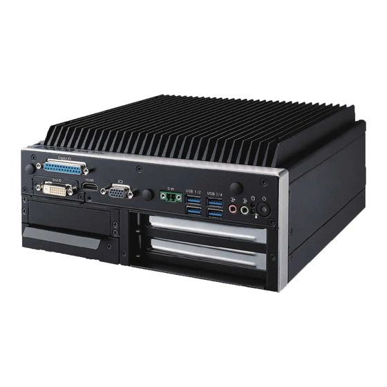
- Page 1 User Manual ARK-3520P Fanless Embedded Box PC...
- Page 2 Attention! Please note: This package contains a hard-copy user manual in Chinese for China CCC certifica- tion purposes, and there is an English user manual included as a PDF file on the CD. Please disregard the Chinese hard copy user manual if the product is not to be sold and/or installed in China.
- Page 3 The documentation and the software included with this product are copyrighted 2017 by Advantech Co., Ltd. All rights are reserved. Advantech Co., Ltd. reserves the right to make improvements in the products described in this manual at any time without notice.
-
Page 4: Declaration Of Conformity
Because of Advantech’s high quality-control standards and rigorous testing, most of our customers never need to use our repair service. If an Advantech product is defec- tive, it will be repaired or replaced at no charge during the warranty period. For out- of-warranty repairs, you will be billed according to the cost of replacement materials, service time and freight. -
Page 5: Technical Support And Assistance
Technical Support and Assistance Visit the Advantech web site at www.advantech.com/support where you can find the latest information about the product. Contact your distributor, sales representative, or Advantech's customer service center for technical support if you need additional assistance. Please have the following information ready before you call: –... -
Page 6: Ordering Information
Ordering Information Model Number Description Intel 6th Gen. Core i (I7-6820EQ) High Performance Fanless ARK-3520P-U8A1E Embedded BOX PC with 2 x PCI Intel 6th Gen. Core i (I5-6440EQ) High Performance Fanless ARK-3520P-U7A1E Embedded BOX PC with 2 x PCIe x 4 Optional Accessories Part Number Description... -
Page 7: Safety Instructions
Safety Instructions Please read these safety instructions carefully. Please keep this User’s Manual for later reference. Please disconnect this equipment from AC outlet before cleaning. Use a damp cloth. Don’t use liquid or sprayed detergent for cleaning. Use moisture sheet or clothe for cleaning. - Page 8 ARK-3520P User Manual viii...
-
Page 9: Table Of Contents
Contents Chapter General Introduction ......1 Introduction ....................2 Product Features..................3 1.2.1 General ..................3 1.2.2 Display ..................3 1.2.3 Ethernet ..................3 Chipset ...................... 4 1.3.1 Functional Specification ..............4 1.3.2 SUSI 4.0..................5 Mechanical Specifications................. 6 1.4.1 Dimensions ................... 6 Figure 1.1 ARK-3520P Mechanical dimension drawing .... - Page 10 Figure 2.10DIO Connector ............18 Table 2.7: DIO Connector Pin Assignments......18 Figure 2.11LED Indicators............18 Figure 2.12HDMI receptacle connector........19 Table 2.8: HDMI Connector Pin Assignments......19 Figure 2.13USB3.0 Connector ........... 19 Table 2.9: USB 3.0 Connector Pin Assignments....... 19 Figure 2.14VGA Connector ............
-
Page 11: Chapter 1 General Introduction
Chapter General Introduction This chapter gives background information on ARK-3520P series. -
Page 12: Introduction
Built in Intelligent Management Tools - Advantech iManager & WISE-PaaS/RMM Advantech iManager provides a valuable suite of programmable APIs such as multi- level watchdog, hardware monitor, system restore, and other user-friendly interface. iManager is an intelligent self-management cross platform tool that monitors system status for problems and takes action if anything is abnormal. -
Page 13: Product Features
– 1 x iDoor – 2 x PCI / 2x PCIex4 – 1 x M.2 (E key for Wifi) Software API: Advantech iManager and WISE-PaaS/RMM - Remote Device Management technology 1.2.2 Display Controller: Intel® HD Graphic 530 ... -
Page 14: Chipset
Chipset 1.3.1 Functional Specification 1.3.1.1 Processor Supports BGA processor (up to 45W): Intel® Core™ i7-6820EQ 2.8GHz with 8M L3 cache Processor Intel® Core™ i5-6440EQ 2.7GHz with 6M L3 cache Intel® Core™ i3-6100E 2.7GHz with 3M L3 cache Supports DDR4 2133 MHz up to 32GB Memory 2 x 260-pin SODIMM socket type... -
Page 15: Susi 4.0
SUSI 4.0 iManager Sequence control Supported 16-bit programmable DIO Watchdog timer Multi-level WDT (set by Advantech iManager) Programmable 1-255 sec / min Hardware monitor CPU Temperature / input Current / input Voltage System information Running HR / Boot record ARK-3520P User Manual... -
Page 16: Mechanical Specifications
Mechanical Specifications 1.4.1 Dimensions 220[8.66] x 101 [3.98] x 233 [9.17] (Unit: mm [Inch}) Figure 1.1 ARK-3520P Mechanical dimension drawing 1.4.2 Weight 4.4 kg (9.7 lb) Power Requirement 1.5.1 System Power Minimum power input: – ARK-3520P: 9 ~ 36V (16.65 ~ 4.16 A) 1.5.2 RTC Battery ... -
Page 17: Environment Specification
Environment Specification 1.6.1 Operating Temperature With Industrial Grade SSD: -20~60° C (-4 ~ 140° F), with air flow, speed=0.7 m/sec With 2.5-inch hard disk: 0 to 40° C (32 ~ 104° F), with air flow, speed=0.7 m/ 1.6.2 Relative Humidity ... - Page 18 ARK-3520P User Manual...
-
Page 19: Chapter 2 Hardware Configuration
Chapter Hardware Configuration... -
Page 20: Introduction
Introduction The following sections show the internal jumpers setting and the external connectors pin assignment for application. Jumpers 2.2.1 Jumper Description You may configure ARK-3520P to match the needs of your application by setting jumpers. A jumper is a metal bridge used to close an electric circuit. It consists of two metal pins and a small metal clip (often protected by a plastic cover) that slides over the pins to connect them. -
Page 21: Jumper Locations
2.2.3 Jumper Locations Figure 2.1 Jumper Layout 2.2.4 Jumper Settings On Motherboard 2.2.4.1 Auto Power on Setting (J1) Auto Power on Setting Part Number 1653002101-02 Footprint HD_2x1P_79_D Description Setting Function Power Button for Power On (Default) (1-2) Auto Power On 2.2.4.2 mSATA / PCIe Setting (J2) mSATA / PCIe Setting... -
Page 22: Jumper Setting
2.2.5 Jumper Setting Jumper setting of IO board of AMO-M016: 2.2.5.1 COM2 RS232 Power Setting (CN4) on AMO-M016 * Please check CN6 on AMO-M016 for COM1 RS-232 setting as well PH_3x2V_S2.00mm Part Number 1653003201 Footprint HD_3x2P_79_D Description Setting Function (1-2) Normal (default) (3-4) (5-6) -
Page 23: Jumper Setting
2.2.6 Jumper Setting Riser card - AMO-R023 jumper setting: 2.2.6.1 AMO-R023 PCI CLK SELECT Setting PH 3 x1P 2.54mm Part Number 1653003100 Footprint HD_3x1P_100_D Setting Function (1-2) 66 MHz (2-3) 33 MHz (Default) ARK-3520P User Manual... -
Page 24: Connectors
Connectors 2.3.1 ARK-3520P External I/O Locations ARK-3520 Front IO Panel Figure 2.2 ARK-3520 Front IO connector drawing ARK-3520 Rear IO Panel Figure 2.3 ARK-3520 Rear IO connector drawing ARK-3520P User Manual... -
Page 25: Ark-3520P Front I/O Connectors
2.3.2 ARK-3520P Front I/O Connectors 2.3.2.1 USB2.0 Connector ARK-3520 provides two USB2.0 interface connectors, which give complete Plug & Play and hot swapping for up to 127 external devices. The USB interface complies with USB UHCI, Rev. 2.0 compliant. The USB interface can be disabled in the system BIOS setup. -
Page 26: Figure 2.6 Power Input Connector
Note! NC represents “No Connection”. 2.3.2.3 Power Input Connector ARK-3520P provides a 4-pin connector, which supports 9 ~ 36 VDC external power input. Please refer to Table. 2.4 for its pin assignments. Figure 2.6 Power Input Connector Table 2.4: Power Input Connector Pin Assignments Signal Name +9 ~ 36 VDC +9 ~ 36 VDC... -
Page 27: Ark-3520 Rear I/O Connectors
2.3.3 ARK-3520 Rear I/O Connectors 2.3.3.1 Power On/Off Button ARK-3520 has a Power On/Off button with LED indicators on the front side that show On status (Green LED) and Off/Suspend status (Orange LED). The Power button supports dual functions: Soft Power -On/Off (Instant off or Delay 4 Seconds then off), and Suspend. -
Page 28: Figure 2.10Dio Connector
2.3.3.3 DIO Connector Figure 2.10 DIO Connector Table 2.7: DIO Connector Pin Assignments Signal Name Signal Name Port0 D0 Port1 D0 Port0 D1 Port1 D1 Port0 D2 Port1 D2 Port0 D3 Port1 D3 Port0 D4 Port1 D4 Port0 D5 Port1 D5 Port0 D6 Port1 D6 Port0 D7... -
Page 29: Figure 2.12Hdmi Receptacle Connector
2.3.3.5 HDMI Connector An integrated, 19-pin receptacle connector HDMI Type A Interface is provided. The HDMI link supports resolutions up to 1920 x 1200 @ 30 Hz. Figure 2.12 HDMI receptacle connector Table 2.8: HDMI Connector Pin Assignments Signal Name Signal Name TMDS Data 2+ TMDS Data 2 shield... -
Page 30: Figure 2.14Vga Connector
2.3.3.7 VGA Connector ARK-3520 provides an integrated 15-pin female VGA digital video interface, which supports up to 1920 x 1200 @ 60 Hz. Please refer to Table 2.10 for its pin assign- ments. Figure 2.14 VGA Connector Table 2.10: VGA Connector Pin Assignments Signal Name Signal Name Green... -
Page 31: Installation
Installation 2.4.1 Memory Installation Unscrew the 4 screws on the top cover, and remove the top cover. Install the memory into the system. Replace the top cover. 2.4.2 HDD/SSD Installation Unscrew 2 screws on the panel side. Place the HDD/SDD. ARK-3520P User Manual... -
Page 32: Remove Bottom Cover
2.4.3 Remove Bottom Cover Unscrew the nine screws on the bottom cover. 2.4.4 Remove Riser Card Bracket Remove the bottom cover (See Chapter 2.4.3). Unscrew the four screws on the riser card. ARK-3520P User Manual... -
Page 33: Module/Minipcie Module/Internal Sim Card Slot Installation
2.4.5 M.2 Module/MiniPCIe Module/Internal SIM Card Slot Installation Remove the bottom cover and the riser card bracket (See Chapter 2.4.3 and Chapter 2.4.4). Install miniPCIe/mSATA module (CN16-1) and fasten the two screws on it. Install miniPCIe module (CN17-1) and fasten the two screws on it (This module is connected with SIM card slot SIM1 in the system). -
Page 34: Remove Hdd Bracket
Remove the bottom cover and the riser card bracket (See Chapter 2.4.3 and Chapter 2.4.4). Unscrew the two screws on the riser card bracket. Install PCI or PCIe device onto the board and use screws to fix it on the bracket. Screw the board back. -
Page 35: Idoor Installation
2.4.8 iDoor Installation Remove the bottom cover and the riser card bracket (See Chapter 2.4.3 and Chapter 2.4.4). Remove the screws on the door. Install iDoor module onto Mini PCIe and iDoor door frame. Screw the two screws. 2.4.9 Optional Module for Third Display Installation Remove the bottom cover and the HDD bracket (See Chapter 2.4.3 and Chap- ter 2.4.7). -
Page 36: Replace Cpu Thermal Grease Pad
2.4.10 Replace CPU thermal Grease Pad Always use the grease pad provided by Advantech. The P/N of the grease pad is: Part Number Description 1990028893N000 Thermal Pad 25x15x0.2mm K=3.4 PSX-D ARK-3520 To ensure the best thermal performance, it is recommended to replace the thermal grease for CPU thermal pole each time the top cover is opened. -
Page 37: Bios Settings
Chapter BIOS Settings... -
Page 38: Introduction
Introduction AMIBIOS has been integrated into zillions of motherboards for over two decades. With the AMIBIOS Setup program, users can modify BIOS settings and control vari- ous system features. This chapter describes the basic navigation of the ARK-3520 BIOS setup screens. AMI's BIOS ROM has a built-in Setup program that allows users to modify the basic system configuration. -
Page 39: Entering Setup
BIOS supports your CPU. If there is no number assigned to the patch code, please contact an Advantech application engineer to obtain an up-to-date patch code file. This will ensure that your CPU‘s system status is valid. -
Page 40: Advanced Bios Features Setup
3.2.2 Advanced BIOS Features Setup Select the Advanced tab from the ARK-3520P setup screen to enter the Advanced BIOS Setup screen. Users can select any item in the left frame of the screen, such as CPU Configuration, to go to the sub menu for that item. Users can display an Advanced BIOS Setup option by highlighting it using the <Arrow>... - Page 41 3.2.2.1 ACPI Settings Enable ACPI Auto Configuration Enable or disable BIOS ACPI auto configuration. Enable Hibernation Enables or Disables System ability to Hibernate (OS/S4 Sleep State). This option may be not effective with some OS. ACPI Sleep State Select the highest ACPI sleep state the system will enter when the SUSPEND button is pressed.
- Page 42 3.2.2.2 AMT Configuration Intel AMT Enable/Disable Intel® Active Management Technology BIOS Extension. BIOS Hotkey Pressed Enable/Disable BIOS hotkey press. MEBx Selection Screen Enable/Disable MEBx selection screen. Hide Un-Configure ME Configuration Prompt Hide Un-Configure ME without password Configuration Prompt. ...
- Page 43 3.2.2.3 PCH-FW Configuration PCH-FW Configuration This page display all information about system ME FW. ME State Set ME to Soft Temporary Disabled. TPM Device Selection Selects TPM device. ARK-3520P User Manual...
- Page 44 3.2.2.4 Embedded Controller Configuration EC Hardware Monitor This page display all information about system Temperature/Voltage/Current. Power Saving Mode This item allows users to set board’s power saving mode when off. Deep Sleep delay time Set delay time for Deep Sleep mode. ...
- Page 45 3.2.2.5 Trusted Computing Trusted Computing Enables or Disables BIOS support for security device. O.S. will not show Secu- rity Device. TCG EFI protocol and INT1A interface will not be available. ARK-3520P User Manual...
- Page 46 3.2.2.6 S5 RTC Wake Settings Wake system from S5 Enable or disable System wake on alarm event. Select FixedTime, system will wake on the hr::min::sec specified. ARK-3520P User Manual...
- Page 47 3.2.2.7 Serial Port Console Redirection Console Redirection This item allows users to enable or disable console redirection for Microsoft Windows Emergency Management Services (EMS). Console Redirection This item allows users to configuration console redirection detail settings. ARK-3520P User Manual...
- Page 48 3.2.2.8 CPU Configuration ARK-3520P User Manual...
- Page 49 Hyper Threading Technology This item allows users to enable or disable Intel? Hyper Threading technology. Active Processor Cores This item allows users to set how many processor cores should be active. Intel Virtualization Technology This item allows users to enable or disable the intel virtualization technology. ...
- Page 50 3.2.2.10 Platform Misc Configuration Native PCIE Enable PCI Express Native Support Enable/Disable. Native ASPM PCI Express Native ASPM Enable/Disable. ARK-3520P User Manual...
- Page 51 3.2.2.11 SATA Configuration SATA Controller Enable / Disable SATA Device. SATA Mode Selection Determine how SATA controller operate. Port 0 / Port 1 / mSATA Enable / Disable Serial ATA Port 1 / Port 2 / mSATA Port. ARK-3520P User Manual...
- Page 52 3.2.2.12 Network Stack Configuration Network Stack Enable/Disable UEFI Network Stack. ARK-3520P User Manual...
- Page 53 3.2.2.13 CSM Configuration CSM Support Enable/Disable CSM Support. GateA20 Active UPON REQUEST - GA20 can be disabled using BIOS services. ALWAYS - do not allow disabling GA20; this option is useful when any RT code is executed above 1MB. ...
- Page 54 3.2.2.14 USB Configuration Legacy USB Support Enables Legacy USB support. AUTO option disables legacy support if no USB devices are connected. DISABLE option will keep USB devices available only for EFI applications. XHCI Hand-off This is a workaround for OSes without XHCI hand-off support. The XHCI owner- ship change should be claimed by XHCI driver.
- Page 55 3.2.2.15 First Super IO Configuration (IT8768E) Serial Port 1 Configuration Set Parameters of Serial Port 1 (COMA). Serial Port 2 Configuration Set Parameters of Serial Port 2 (COMB). Serial Port 3 Configuration Set Parameters of Serial Port 3 (COMC). ...
- Page 56 3.2.2.16 Second Super IO Configuration (NCT6106D) Serial Port 5 Configuration Set Parameters of Serial Port 5 (COMA2). Serial Port 6 Configuration Set Parameters of Serial Port 6 (COMB2). Serial Port 7 Configuration Set Parameters of Serial Port 7 (COMC2). ...
- Page 57 3.2.2.17 NVMe Configuration NVMe Device Options Settings ARK-3520P User Manual...
-
Page 58: Chipset Configuration
3.2.3 Chipset Configuration Select the Chipset tab from the ARK-3520 setup screen to enter the Chipset BIOS Setup screen. You can display a Chipset BIOS Setup option by highlighting it using the <Arrow> keys. All Plug and Play BIOS Setup options are described in this sec- tion. - Page 59 3.2.3.1 System Agent (SA) Configuration Above 4GB MMIO BIOS assigment Enable/Disable above 4GB Memory Mapped IO BIOS assignment. ARK-3520P User Manual...
- Page 60 3.2.3.2 Graphics Configuration Graphics Turbo IMON Current Graphics turbo IMON current values supported. Skip Scaning of External Gfx Card If Enable, it will not scan for External Gfx Card on PEG and PCH PCIE Ports. Primary Display Select which of IGFX/PEG/PCI Graphics device should be Primary Display Or select SG for Switchable Gfx.
- Page 61 Cdynmax Clamping Enable Enable/Disable Cdynmax Clamping. Cd Clock Frequency Select the highest Cd Clock frequency supported by the platform. 3.2.3.3 LCD Control Primary IGFX Boot Display Select the Video Device which will be activated during POST. This has no effect if an external graphics present.
- Page 62 3.2.3.4 Memory Configuration Options Max TOLUD Maximum Value of TOLUD. 3.2.3.5 GT – Power Management Control RC6 Render Standby) Check to enable render standby support. ARK-3520P User Manual...
- Page 63 3.2.3.6 PEG Port Configuration PEG Link and Speed Information Enable Root Port Enable or Disable the Root Port. Max Link Speed Configure PEG Max Speed. Max Link Width Force PEG link to retrain to X1/2/4/8 or Auto. ...
- Page 64 3.2.3.7 PCH-IO Configuration PCI Express Configuration PCI Express Configuration Settings. USB Configuration USB Configuration Settings. HD Audio Configuration HD Audio Susbsystem Configuration Settings. SB Porting Configuration SB Porting Configuration Settings. PCH LAN Controller Enable or Disable onboard NIC. ...
- Page 65 3.2.3.8 PCI Express Configuration PCI Express Clock Gating Enable or disable PCI Express Clock Gating for each root port. DMI Link ASPM Control Enable/Disable the control of Active State Power Management on SA side of the DMI Link. ...
- Page 66 3.2.3.9 USB Configuration USB Precondition Precondition work on USB host controller and root ports for faster enumeration. XHCI Disable Compliance mode Option to disable Compliance Mode. 3.2.3.10 HD Audio Configuration HD Audio Control Detection of the HD-Audio device. Disabled = HDA will be uncondition- ally disabled.
- Page 67 3.2.3.11 SB Porting Configuration SATA RAID ROM Run the Legacy ROM or UEFI Driver. ARK-3520P User Manual...
-
Page 68: Security
3.2.4 Security Select Security Setup from the PCM-3365 Setup main BIOS setup menu. All Security Setup options, such as password protection and virus protection are described in this section. To access the sub menu for the following items, select the item and press <Enter>: ... -
Page 69: Boot
3.2.5 Boot Setup Prompt Timeout Number of seconds that the firmware will wait before initiating the original default boot selection. A value of 0 indicates that the default boot selection is to be initiated immediately on boot. A value of 65535(0xFFFF) indicates that firm- ware will wait for user input before booting. -
Page 70: Save & Exit
3.2.6 Save & Exit Save Changes and Exit This item allows you to exit system setup after saving the changes. Discard Changes and Exit This item allows you to exit system setup without saving any changes. Save Changes and Reset This item allows you to reset the system after saving the changes. -
Page 71: Appendix A Watchdog Timer Sample Code
Appendix Watchdog Timer Sample Code... -
Page 72: Ec Watchdog Timer Sample Code
EC Watchdog Timer Sample Code EC_Command_Port = 0x29Ah EC_Data_Port = 0x299h Write EC HW ram = 0x89 Watch dog event flag = 0x57 Watchdog reset delay time = 0x5E Reset event = 0x04 Start WDT function = 0x28 ==================================================== .model small .486p .stack 256 .data... - Page 73 ARK-3520P User Manual...
- Page 74 ARK-3520P User Manual...
-
Page 75: Usb 3.0 Drivers Installation
Appendix USB 3.0 Drivers Installation Instruction... -
Page 76: Usb 3.0 Drivers Installation Instruction
USB 3.0 Drivers Installation Instruction For customers using Windows 7 OS, they need to install drivers to active the USB 3.0 function. Please download driver installation instructions from the Intel website. (https:/ /downloadcenter.intel.com/download/25476/Windows-7-USB-3-0-Creator-Utility) ARK-3520P User Manual... - Page 77 ARK-3520P User Manual...
- Page 78 No part of this publication may be reproduced in any form or by any means, electronic, photocopying, recording or otherwise, without prior written permis- sion of the publisher. All brand and product names are trademarks or registered trademarks of their respective companies. © Advantech Co., Ltd. 2017...
Need help?
Do you have a question about the ARK-3520P series and is the answer not in the manual?
Questions and answers