Table of Contents
Advertisement
Quick Links
Advertisement
Table of Contents

Related Manuals for Advantech ARK-3520L


Summary of Contents for Advantech ARK-3520L
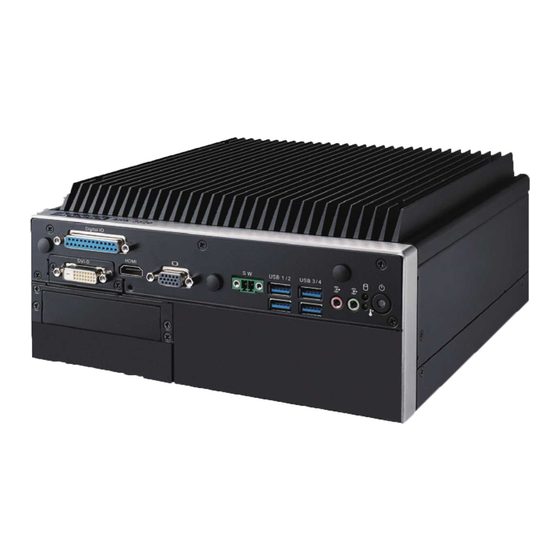
- Page 1 User Manual ARK-3520L Fanless Embedded Box PC...
- Page 2 English user manual included as a PDF file on the CD. Please disregard the Chinese hard copy user manual if the product is not to be sold and/or installed in China. 甲類警語: 警告使用者:這是甲類資訊產品,在居住的環境使用時,可能會造成輻射干擾,在這 種情況下,使用者會被要求採取某些適當措施。 ARK-3520L User Manual...
- Page 3 The documentation and the software included with this product are copyrighted 2017 by Advantech Co., Ltd. All rights are reserved. Advantech Co., Ltd. reserves the right to make improvements in the products described in this manual at any time without notice.
- Page 4 Because of Advantech’s high quality-control standards and rigorous testing, most of our customers never need to use our repair service. If an Advantech product is defec- tive, it will be repaired or replaced at no charge during the warranty period. For out- of-warranty repairs, you will be billed according to the cost of replacement materials, service time and freight.
- Page 5 Technical Support and Assistance Visit the Advantech web site at www.advantech.com/support where you can find the latest information about the product. Contact your distributor, sales representative, or Advantech's customer service center for technical support if you need additional assistance. Please have the following information ready before you call: –...
- Page 6 Optional Accessories Part Number Description XARK-DPS-150AB-15 AC-to-DC Adapter, DC12V 150W 1702002600 Power cable 3-pin 183cm, USA type 1702002605 Power cable 3-pin 183cm, EU type 1702031801 Power cable 3-pin 183cm, UK type 1700000237 Power Cord, 3-Pin 183cm, PSE ARK-3520L User Manual...
- Page 7 RESTRICTED ACCESS AREA: The equipment should only be installed in a Restricted Access Area. DISCLAIMER: This set of instructions is given according to IEC 704-1. Advan- tech disclaims all responsibility for the accuracy of any statements contained herein. ARK-3520L User Manual...
- Page 8 ARK-3520L User Manual viii...
-
Page 9: Table Of Contents
Chipset ...................... 4 1.3.1 Functional Specification ..............4 1.3.2 SUSI 4.0..................5 Mechanical Specifications................. 6 1.4.1 Dimensions ................... 6 Figure 1.1 ARK-3520L Mechanical dimension drawing....6 1.4.2 Weight................... 6 Power Requirement .................. 6 1.5.1 System Power................6 1.5.2 RTC Battery .................. 6 Environment Specification................. - Page 10 Boot .................... 57 3.2.6 Save & Exit ................. 58 Appendix A Watchdog Timer Sample Code ..59 EC Watchdog Timer Sample Code............60 Appendix B USB 3.0 Drivers Installation Instruction ......... 63 USB 3.0 Drivers Installation Instruction ..........64 ARK-3520L User Manual...
-
Page 11: Chapter 1 General Introduction
Chapter General Introduction This chapter gives background information on ARK-3520L series. -
Page 12: Introduction
Built in Intelligent Management Tools - Advantech iManager & WISE-PaaS/RMM Advantech iManager provides a valuable suite of programmable APIs such as multi- level watchdog, hardware monitor, system restore, and other user-friendly interface. iManager is an intelligent self-management cross platform tool that monitors system status for problems and takes action if anything is abnormal. -
Page 13: Product Features
1 x iDoor – 2 x PCI + 1 x PCIe x 4 – 1 x M.2 (E key for Wifi) Software API: Advantech iManager and WISE-PaaS/RMM - Remote Device Management technology 1.2.2 Display Controller: Intel® HD Graphic 530 ... -
Page 14: Chipset
Supports IRQ Sharing among serial ports under Microsoft Serial ports Windows OS COM1,COM2,COM3,COM4: RS-232/422/485 COM5,COM6,COM7,COM8: RS-232 LAN1 Intel i219LM, LAN2 Intel i210 IT Supports 10/100/1000 Mbps. Ethernet LAN Connectors: Phone Jack RJ45 8P 90D(F) ARK-3520L User Manual... -
Page 15: Susi 4.0
SUSI 4.0 iManager Sequence control Supported 16-bit programmable DIO Watchdog timer Multi-level WDT (set by Advantech iManager) Programmable 1-255 sec / min Hardware monitor CPU Temperature / input Current / input Voltage System information Running HR / Boot record ARK-3520L User Manual... -
Page 16: Mechanical Specifications
Mechanical Specifications 1.4.1 Dimensions 220[8.66] x 101 [3.98] x 233 [9.17] (Unit: mm [Inch}) Figure 1.1 ARK-3520L Mechanical dimension drawing 1.4.2 Weight 4.4 kg (9.7 lb) Power Requirement 1.5.1 System Power Minimum power input: – 12V (12.5A) 1.5.2 RTC Battery ... -
Page 17: Environment Specification
For system equipped with SSD/mSATA: 3Grms, IEC 60068-2-64, random, 5 ~ 500 Hz 1.6.5 Shock during Operation For system equipped with SSD/mSATA: 30G, IEC 60068-2-27, half sin, 11 ms duration 1.6.6 Safety UL, CB, CCC, BSMI 1.6.7 CE, FCC, CCC, BSMI ARK-3520L User Manual... - Page 18 ARK-3520L User Manual...
-
Page 19: Chapter 2 Hardware Configuration
Chapter Hardware Configuration... -
Page 20: Introduction
2.2.1 Jumper Description You may configure ARK-3520L to match the needs of your application by setting jumpers. A jumper is a metal bridge used to close an electric circuit. It consists of two metal pins and a small metal clip (often protected by a plastic cover) that slides over the pins to connect them. -
Page 21: Jumper Locations
Power Button for Power On (Default) (1-2) Auto Power On 2.2.4.2 mSATA / PCIe Setting (J2) mSATA / PCIe Setting Part Number 1653003101 Footprint HD_2x1P_79_D Description PIN HEADER 2x1P 2.0mm 180D(M) DIP 21N12050 Setting Function (1-2) mSATA (2-3) PCIe (Default) ARK-3520L User Manual... -
Page 22: Jumper Setting
Part Number 1653003201 Footprint HD_3x2P_79_D Description Setting Function (1-2) Normal (default) (3-4) (5-6) +12V 2.2.5.2 COM1 RS232 Power Setting (CN6) on AMO-M016 PH_3x2V_S2.00mm Part Number 1653003201 Footprint HD_3x2P_79_D Description Setting Function (1-2) Normal (default) (3-4) (5-6) +12V ARK-3520L User Manual... -
Page 23: Connectors
Connectors 2.3.1 ARK-3520L External I/O Locations ARK-3520 Front IO Panel Figure 2.2 ARK-3520 Front IO connector drawing ARK-3520 Rear IO Panel Figure 2.3 ARK-3520 Rear IO connector drawing ARK-3520L User Manual... -
Page 24: Ark-3520L Front I/O Connectors
2.3.2 ARK-3520L Front I/O Connectors 2.3.2.1 USB2.0 Connector ARK-3520 provides two USB2.0 interface connectors, which give complete Plug & Play and hot swapping for up to 127 external devices. The USB interface complies with USB UHCI, Rev. 2.0 compliant. The USB interface can be disabled in the system BIOS setup. -
Page 25: Ark-3520 Rear I/O Connectors
On status (Green LED) and Off/Suspend status (Orange LED). The Power button supports dual functions: Soft Power -On/Off (Instant off or Delay 4 Seconds then off), and Suspend. Figure 2.7 Power ON/OFF Button 2.3.3.2 Audio Connector ARK-3520 offers two stereo audio ports: Line_Out, Mic_In. ARK-3520L User Manual... - Page 26 Port1 D7 Note! NC represents “No Connection”. 2.3.3.4 LED Indicators There are two LEDs on the front panel that indicate system status: The thermal LED is for system thermal alarm status; and HDD LED is for HDD status. ARK-3520L User Manual...
- Page 27 UHCI, Rev. 3.0 standards. Please refer to Table 2.9 for its pin assignments. USB 3.0 connectors contain legacy pins to interface to USB 2.0 devices, and a new set of pins for USB 3.0 connectivity. Figure 2.12 USB3.0 Connector Table 2.8: USB 3.0 Connector Pin Assignments Signal Name Signal Name ARK-3520L User Manual...
- Page 28 Blue DDAT H-SYNC V-SYNC DCLK 2.3.3.8 Power Switch Connector ARK-3520L provides an additional interface for connecting cables to switch on/off the power. Figure 2.14 Power Switch Table 2.10: Power Switch Connector Pin Assignments Signal Name Power switch ARK-3520L User Manual...
-
Page 29: Installation
Memory Installation Unscrew the 4 screws on the top cover, and remove the top cover. Install the memory into the system. Replace the top cover. 2.4.2 Remove Bottom Cover Unscrew the ten screws on the bottom cover. ARK-3520L User Manual... -
Page 30: Internal Hdd/Ssd Installation (Default And Optional Amk-A0022E)
Remove the bottom cover (Reference Chapter 2.4.2) Install 2pcs of SATA cable screws (1930004828) Plug SATA HDD cable connector First HDD: CN12/CN13 2nd HDD: CN11/CN14 Install HDD dumper screws (1930004766) Install HDD and HDD door bracket screws (1930001241) ARK-3520L User Manual... -
Page 31: Module/Minipcie Module/Internal Sim Card Slot Installation
Install M.2 module (NGFF_1) and fasten the one screw on it. 2.4.6 iDoor Installation Remove the bottom cover (See Chapter 2.4.2). Remove the screws on the door. Install iDoor module onto Mini PCIe and iDoor door frame. Screw the two screws. ARK-3520L User Manual... -
Page 32: Optional Module For Third Display Installation
Install the optional module and fasten the two screws. Replace the panel and screw it. Install optional Riser card AMO-3501E (2PCI +1 x PCIe x 4) 2.5.1 Install chassis bracket Install 8 pcs screws of chassis bracket ARK-3520L User Manual... -
Page 33: Install Riser And Idoor Bracket
2.5.2 Install Riser and iDoor bracket Install 8 pcs screws of riser card and iDoor bracket 2.5.3 Install reveal plate Install 2 pcs reveal plate with 4 pcs screws ARK-3520L User Manual... -
Page 34: Install Bottom Case
Install 9pcs screws of bottom case 2.5.5 Replace CPU thermal Grease Pad Always use the grease pad provided by Advantech. The P/N of the grease pad is: Part Number Description 1990028893N000 Thermal Pad 25x15x0.2mm K=3.4 PSX-D ARK-3520 To ensure the best thermal performance, it is recommended to replace the thermal grease for CPU thermal pole each time the top cover is opened. -
Page 35: Bios Settings
Chapter BIOS Settings... -
Page 36: Introduction
BIOS setup screens. AMI's BIOS ROM has a built-in Setup program that allows users to modify the basic system configuration. This information is stored in flash ROM so it retains the Setup information when the power is turned off. ARK-3520L User Manual... -
Page 37: Entering Setup
BIOS supports your CPU. If there is no number assigned to the patch code, please contact an Advantech application engineer to obtain an up-to-date patch code file. This will ensure that your CPU‘s system status is valid. -
Page 38: Advanced Bios Features Setup
3.2.2 Advanced BIOS Features Setup Select the Advanced tab from the ARK-3520L setup screen to enter the Advanced BIOS Setup screen. Users can select any item in the left frame of the screen, such as CPU Configuration, to go to the sub menu for that item. Users can display an Advanced BIOS Setup option by highlighting it using the <Arrow>... - Page 39 Select the highest ACPI sleep state the system will enter when the SUSPEND button is pressed. Lock Legacy Resources Enables or Disables Lock of Legacy Resources. S3 Video Repost Enable or Disable S3 Video Repost. ARK-3520L User Manual...
- Page 40 Activate Remote Assistance Process Trigger CIRA boot. USB Provisioning of AMT Enable/Disable of AMT USB Provisioning. PET Progress User can Enable/Disable PET Events progress to receive PET events or not. Watch Dog Enable/Disable WatchDog Timer. ARK-3520L User Manual...
- Page 41 3.2.2.3 PCH-FW Configuration PCH-FW Configuration This page display all information about system ME FW. ME State Set ME to Soft Temporary Disabled. TPM Device Selection Selects TPM device. ARK-3520L User Manual...
- Page 42 This item allows users to set board’s power saving mode when off. Deep Sleep delay time Set delay time for Deep Sleep mode. Watch Dog Timer This item allows users to select EC watchdog timer. ARK-3520L User Manual...
- Page 43 3.2.2.5 Trusted Computing Trusted Computing Enables or Disables BIOS support for security device. O.S. will not show Secu- rity Device. TCG EFI protocol and INT1A interface will not be available. ARK-3520L User Manual...
- Page 44 3.2.2.6 S5 RTC Wake Settings Wake system from S5 Enable or disable System wake on alarm event. Select FixedTime, system will wake on the hr::min::sec specified. ARK-3520L User Manual...
- Page 45 Serial Port Console Redirection Console Redirection This item allows users to enable or disable console redirection for Microsoft Windows Emergency Management Services (EMS). Console Redirection This item allows users to configuration console redirection detail settings. ARK-3520L User Manual...
- Page 46 3.2.2.8 CPU Configuration ARK-3520L User Manual...
- Page 47 Enable or disable CPU C states. CState Pre-Wake Disable – to disable the CState Pre-Wake. Package C State limit Package C State limit. 3.2.2.9 Intel TXT Information Intel TXT Information Display Intel TXT information. ARK-3520L User Manual...
- Page 48 3.2.2.10 Platform Misc Configuration Native PCIE Enable PCI Express Native Support Enable/Disable. Native ASPM PCI Express Native ASPM Enable/Disable. ARK-3520L User Manual...
- Page 49 SATA Controller Enable / Disable SATA Device. SATA Mode Selection Determine how SATA controller operate. Port 0 / Port 1 / mSATA Enable / Disable Serial ATA Port 1 / Port 2 / mSATA Port. ARK-3520L User Manual...
- Page 50 3.2.2.12 Network Stack Configuration Network Stack Enable/Disable UEFI Network Stack. ARK-3520L User Manual...
- Page 51 Storage Controls the execution of UEFI and Legacy Storage OpROM. Video Controls the execution of UEFI and Legacy Video OpROM. Other PCI devices Determines OpROM execution policy for devices other than Network, Storage, or Video. ARK-3520L User Manual...
- Page 52 Maximum time the device will take before it properly reports itself to the Host Controller. 'Auto' uses default value: for a Root port it is 100 ms, for a Hub port the delay is taken from Hub descriptor. ARK-3520L User Manual...
- Page 53 Set Parameters of Serial Port 1 (COMA). Serial Port 2 Configuration Set Parameters of Serial Port 2 (COMB). Serial Port 3 Configuration Set Parameters of Serial Port 3 (COMC). Serial Port 4 Configuration Set Parameters of Serial Port 4 (COMD). ARK-3520L User Manual...
- Page 54 Set Parameters of Serial Port 6 (COMB2). Serial Port 7 Configuration Set Parameters of Serial Port 7 (COMC2). Serial Port 8 Configuration Set Parameters of Serial Port 8 (COMD2). Parallel Port Configuration Set Parameters of Parallel Port (LPT/LPTE). ARK-3520L User Manual...
- Page 55 3.2.2.17 NVMe Configuration NVMe Device Options Settings ARK-3520L User Manual...
-
Page 56: Chipset Configuration
Setup screen. You can display a Chipset BIOS Setup option by highlighting it using the <Arrow> keys. All Plug and Play BIOS Setup options are described in this sec- tion. The Plug and Play BIOS Setup screen is shown below. ARK-3520L User Manual... - Page 57 3.2.3.1 System Agent (SA) Configuration Above 4GB MMIO BIOS assigment Enable/Disable above 4GB Memory Mapped IO BIOS assignment. ARK-3520L User Manual...
- Page 58 Select DVMT 5.0 Total Graphic Memory size used by the Internal Graphics Device. Gfx Low Power Mode This option is applicable for SFF only. VDD Enable Enable/Disable forcing of VDD in the BIOS. PM Support Enable/Disable PM Support. PAVP Enable Enable/Disable PAVP. ARK-3520L User Manual...
- Page 59 Select the Video Device which will be activated during POST. This has no effect if an external graphics present. Secondary boot display selection will appear based on your selection. VGA modes will be supported only on primary display. ARK-3520L User Manual...
- Page 60 3.2.3.4 Memory Configuration Options Max TOLUD Maximum Value of TOLUD. 3.2.3.5 GT – Power Management Control RC6 Render Standby) Check to enable render standby support. ARK-3520L User Manual...
- Page 61 Configure PEG Max Speed. Max Link Width Force PEG link to retrain to X1/2/4/8 or Auto. ASPM Enable PCI Express Active State Power Management settings. Detect Non-Compliance Device Detect Non-Compliance PCI Express Device in PEG. ARK-3520L User Manual...
- Page 62 Enable or Disable PCIE to wake the system from S5. High Precision Timer Enable or Disable High Precision Event Timer. State After S3 Specify what state to go to when power is re-applied after a power failure (G3 state). ARK-3520L User Manual...
- Page 63 Enable or disable PCI Express Clock Gating for each root port. DMI Link ASPM Control Enable/Disable the control of Active State Power Management on SA side of the DMI Link. PCI Express Root Port 1/2/3/4/7/8/9 PCI Express Port 1/2/3/4/7/8/9 Settings. ARK-3520L User Manual...
- Page 64 XHCI Disable Compliance mode Option to disable Compliance Mode. 3.2.3.10 HD Audio Configuration HD Audio Control Detection of the HD-Audio device. Disabled = HDA will be uncondition- ally disabled. Enabled = HDA will be unconditionally Enabled. ARK-3520L User Manual...
- Page 65 3.2.3.11 SB Porting Configuration SATA RAID ROM Run the Legacy ROM or UEFI Driver. ARK-3520L User Manual...
-
Page 66: Security
To access the sub menu for the following items, select the item and press <Enter>: Change Administrator / User Password Select this option and press <ENTER> to access the sub menu, and then type in the password. ARK-3520L User Manual... -
Page 67: Boot
Enables or disables boot with initialization of a minimal set of devices required to launch active boot option. Has no effect for BBS boot options. New Boot Option Policy Controls the placement of newly detected UEFI boot options. ARK-3520L User Manual... -
Page 68: Save & Exit
This item allows you to save the changes done so far as user defaults. Restore User Defaults This item allows you to restore the user defaults to all the options. Boot Override Boot device select can override your boot priority. ARK-3520L User Manual... -
Page 69: Appendix A Watchdog Timer Sample Code
Appendix Watchdog Timer Sample Code... -
Page 70: Ec Watchdog Timer Sample Code
57h ; Watch dog event flag. out dx,al mov dx, EC_Data_Port mov al, 04h ; Reset event. out dx,al mov dx, EC_Command_Port mov al,28h ; start WDT function. (Stop: 0x29, Reset: 0x2A) out dx,al .exit ARK-3520L User Manual... - Page 71 ARK-3520L User Manual...
- Page 72 ARK-3520L User Manual...
-
Page 73: Usb 3.0 Drivers Installation
Appendix USB 3.0 Drivers Installation Instruction... -
Page 74: Usb 3.0 Drivers Installation Instruction
USB 3.0 Drivers Installation Instruction For customers using Windows 7 OS, they need to install drivers to active the USB 3.0 function. Please download driver installation instructions from the Intel website. (https:/ /downloadcenter.intel.com/download/25476/Windows-7-USB-3-0-Creator-Utility) ARK-3520L User Manual... - Page 75 ARK-3520L User Manual...
- Page 76 No part of this publication may be reproduced in any form or by any means, electronic, photocopying, recording or otherwise, without prior written permis- sion of the publisher. All brand and product names are trademarks or registered trademarks of their respective companies. © Advantech Co., Ltd. 2017...
Need help?
Do you have a question about the ARK-3520L and is the answer not in the manual?
Questions and answers