
Related Manuals for Advantech PPC-S155T


Summary of Contents for Advantech PPC-S155T
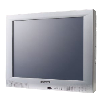
- Page 1 User Manual PPC-S155T Slim Panel PC Panel PC with 15" Color TFT LCD ® ® ® Intel Pentium / Celeron Processor...
- Page 2 No part of this manual may be reproduced, copied, translated or transmitted in any form or by any means without the prior written permission of Advantech Co., Ltd. Information provided in this manual is intended to be accurate and reliable. How- ever, Advantech Co., Ltd.
-
Page 3: Declaration Of Conformity
This product has passed the CE test for environmental specifications when shielded cables are used for external wiring. We recommend the use of shielded cables. This kind of cable is available from Advantech. Please contact your local supplier for ordering information. -
Page 4: Technical Support And Assistance
Please send all such - in writing to: support@advantech.com Technical Support and Assistance Visit the Advantech web site at www.advantech.com/support. Here, the latest information about the product is available. Contact the distributor, sales representative, or Advantech's customer service center for technical support if additional assistance is needed. Please have the following information ready before calling: –... -
Page 5: Packing List
Before setting up the system, check that the items listed below are included and in good condition. If any item does not accord with the table, please contact the dealer immediately. PPC-S155T series panel PC Users manual Accessories for PPC-S155T –... -
Page 6: Safety Instructions
The sound pressure level at the operator's position according to IEC 704-1:1982 is no more than 70 dB (A). DISCLAIMER: This set of instructions is given according to IEC 704-1. Advantech disclaims all responsibility for the accuracy of any statements contained herein. - Page 7 Anweisung des Herstellers. Der arbeitsplatzbezogene Schalldruckpegel nach DIN 45 635 Teil 1000 beträgt 70dB(A) oder weiger. Haftungsausschluss: Die Bedienungsanleitungen wurden entsprechend der IEC- 704-1 erstellt. Advantech lehnt jegliche Verantwortung für die Richtigkeit der in diesem Zusammenhang getätigten Aussagen ab. PPC-S155T User Manual...
- Page 8 Disconnect power before making any configuration changes. The sudden rush of power when connecting a jumper or installing a card may damage sensitive electronic components. Contact information: Our European representative: Advantech Europe GmbH Kolberger Straße 7 D-40599 Düsseldorf, Germany Tel: 49-211-97477350 Fax: 49-211-97477300 PPC-S155T User Manual viii...
-
Page 9: Table Of Contents
Optional modules ................4 1.2.8 Environment.................. 4 LCD Specifications..................5 Dimensions ....................5 Figure 1.1 Dimensions of the PPC-S155T........5 Chapter System Setup ........7 A Quick Tour of the Panel PC ..............8 Figure 2.1 Front view of the panel PC ......... 8 Figure 2.2 Left side view of the panel PC ........ - Page 10 Figure 4.4 CN19 jumper settings..........22 Table 4.1: CN19 ................ 22 Table 4.2: Clear CMOS / External RTC (JP1)9......22 Connectors....................23 Figure 4.5 Locating connectors on the MB........ 23 Table 4.3: PPC-S155T Connectors........... 24 Chapter Intel Chipset ........25 Introduction ..................... 26 5.1.1...
- Page 11 Table B.16:Parallel Port Connector (CN8)........57 B.17 TV OUT (S-VIDEO) connector (Reserved)(CN6)........57 Table B.17:TV OUT (S-VIDEO) connector (Reserved)(CN6) ..57 B.18 PS/2 Keyboard & mouse port (CN14) ............. 57 Table B.18:PS/2 Keyboard & mouse port(CN14) ....... 57 PPC-S155T User Manual...
-
Page 13: Chapter 1 General Information
Chapter General Information This chapter gives background information on the PPC-S155T panel PC. Sections include: Introduction General Specifications LCD Specifications Dimensions... -
Page 14: Introduction
It is a PC-based system complete with a 15” color TFT LCD display, on-board PCI Ethernet controller, multi-COM port interfaces and an 18-bit stereo audio controller. The PPC-S155T is one of the most compact and user-friendly multi-functional computers available today. -
Page 15: General Specifications
Chipset: Integrated in the Intel 915GME south bridge Audio controller: AC97 Ver. 2.0 compliant interface, Multi stream Direct sound and Direct Sound 3D acceleration Stereo sound: 18-bit full-duplex codec Audio interface: Microphone in, Line-n, Line-out, Speaker L, Speaker R PPC-S155T User Manual... -
Page 16: Pci Bus Ethernet Interface
Relative humidity: 10 ~ 95% @ 40° C (non-condensing) Shock: 10 G peak acceleration (11 msec duration) Certification: – EMC: BSMI, VCCI, CE, FCC, Calss B, CCC – Safety: CB, CE, UL Vibration: 5 ~ 500 Hz 1 G RMS Random vibration PPC-S155T User Manual... -
Page 17: Lcd Specifications
The color LCD display installed in the panel PC is high-quality and reli- able. However, it may contain a few defective pixels which do not always illuminate. With current technology, it is impossible to completely eliminate defective pixels. Advantech is actively working to improve this technology. Dimensions Figure 1.1 Dimensions of the PPC-S155T... -
Page 19: Chapter 2 System Setup
Chapter System Setup This chapter details system setup on the PPC-S155T panel PC. Sections include: A Quick Tour of the Panel PC Installation procedures Running the BIOS Setup Pro- gram Installing System Software Installing the Drivers... -
Page 20: A Quick Tour Of The Panel Pc
The floppy disk drive, CD-ROM drive is located on the left side of the panel PC, as shown in Fig. 2-2. • Compact CD-ROM drive • • FDD slot • Figure 2.2 Left side view of the panel PC PPC-S155T User Manual... -
Page 21: Figure 2.3 Rear View Of The Panel Pc
O ports, including serial ports, VGA port, the Ethernet port, USB ports, the micro- phone jack, and so on.) Figure 2.3 Rear view of the panel PC Figure 2.4 Rear and bottom view of the panel PC Figure 2-4 shows the I/O section and power switch of the panel PC. PPC-S155T User Manual... -
Page 22: Installation Procedures
Before starting the computer, connect the Y-shaped adaptor to the PS/2 mouse and keyboard port on the I/O section of the panel PC. Then connect the necessary mouse or keyboard to the Y-shaped adapter or serial ports. Figure 2.6 Connecting the Y-shaped adaptor to the PS2 mouse and keyboard PPC-S155T User Manual... -
Page 23: Switching On The Power
When the switch is in the vertical position, as shown in Figure 2-7, it can be pushed to open or close the computer power supply. Power switch (Lock status) Figure 2.7 Power switch in lock status Power switch (Open status) Figure 2.8 Power switch in open status PPC-S155T User Manual... -
Page 24: Running The Bios Setup Program
Running the BIOS Setup Program The PPC-S155T panel PC was most likely set up and pre-configured by the dealer prior to delivery. However, it may be necessary to use the panel PC's BIOS (Basic Input-Output System) setup program to change the system configuration information, like the current date and time, or the specific type of hard drive. -
Page 25: Installing The Drivers
Note! The drivers and utilities used for the PPC-S155T panel PCs are subject to change without notice. If in doubt, check Advantech's website or con- tact our application engineers for the latest information regarding drivers and utilities. -
Page 27: Chapter 3 Hardware & Peripheral Installation
Chapter Hardware & Peripheral Installation This chapter details the installa- tion of the PPC-S155T panel PC hardware. Sections include: Overview of Hardware Installa- tion and Upgrading Installing the 2.5" Hard Disk Drive (HDD) Installing the Central Process- ing Unit (CPU) and SDRAM... -
Page 28: Overview
HDD, with Pin 1 on the cable corresponding to Pin 1 on the HDD. Put the HDD bracket and the new HDD back into the original position inside the chassis, and fasten the four screws to fix it. Figure 3.1 Attach the HDD to the HDD bracket PPC-S155T User Manual... -
Page 29: Figure 3.2 Connect The Hdd To The Hdd Cable
Slide the CPU gently inside. The CPU pins should insert easily. If they do not, pull the lever up a little more and check to make sure that the pins of the CPU correspond with the holes of the socket. DO NOT USE EXCESSIVE FORCE! PPC-S155T User Manual... -
Page 30: Figure 3.4 Cpu Socket
PC. It is advisable to contact technical support for assistance before disassembling the PPC. Finally, put the heatsink with the fan back and refasten the four screws. Then put back and fix the plastic cover. Figure 3.5 SDRAM Socket PPC-S155T User Manual... -
Page 31: Chapter 4 Jumper Settings And Connectors
Chapter Jumper Settings and Connectors This chapter tells how to set up the panel PC hardware, including instructions on setting jumpers and connecting peripherals, switches and indicators. Be sure to read all the safety precautions before beginning installation pro- cedures. Sections include: Motherboard appearance Position of connectors... -
Page 32: Setting Jumpers And Switches
A pair of needle-nose pliers may be helpful when working with jumpers. If there are any doubts about the best hardware configuration for the application, contact the local distributor or sales representative before making any changes. Figure 4.1 Motherboard appearance PPC-S155T User Manual... -
Page 33: Locating Jumpers And Switches
SW1 select DDR power and CPU type Three different types of CPU may be installed on the motherboard. The diagram below shows the correct switch settings for each type of CPU. Dothan Banias 533 Banias 400 Figure 4.3 SW1 switch settings PPC-S155T User Manual... -
Page 34: Figure 4.4 Cn19 Jumper Settings
Warning! To avoid damaging the computer, always turn off the power supply before setting “Clear CMOS”. Set the jumper back to “Normal operation” before turning on the power supply. Table 4.3: Clear CMOS / External RTC (JP1) Normal Operation Clear CMOS PPC-S155T User Manual... -
Page 35: Connectors
SATA Con CN14 Speaker Con CN16 COM4 Con CN23 Power In CN24 CN27 CN20 CN26 CN21 CN22 CN25 PS2-KB/MS Con Audio Con COM1 Con LAN Con VGA Con Ext USB Con Figure 4.5 Locating connectors on the MB PPC-S155T User Manual... - Page 36 Table 4.4: PPC-S155T Connectors Connector Description LVDS CONN Mini PCI CONN CD-ROM CONN CPU Fan CONN (+12V) DDR2 CONN (RVS) CF card CONN DDR2 CONN (STD) System Fan CONN (+5V) CN10 BIOS CONN CN11 Front panel CONN CN12 Inv. CONN...
-
Page 37: Intel Chipset
Chapter Intel Chipset This chapter provides informa- tion on Intel chipset configuration. Sections include: Introduction Installation of Intel INF driver Installation of Intel IAA driver Further information... -
Page 38: Introduction
Introduction The PPC-S155T uses the combination of Intel 915GME north bridge and Intel 82801FBM ICH6 Mobile chipsets. The Mobile Intel® 915GME Chipset is an optimized integrated graphics solution with a 400 MHz and 533 MHz front-side bus. The integrated 32-bit 3D graphics engine, based on Intel®... -
Page 39: Agp Svga Setup
Chapter AGP SVGA Setup This chapter describes how to setup the SVGA drivers and set- tings. Sections include: Installation of SVGA Drivers for Windows 2000/XP Further Information... -
Page 40: Introduction
6.1.1 Chipset The PPC-S155T uses an integrated graphics chipset in Intel 915 GME chipset. It integrates a 32-bit 3D graphics engine, based on an Intel® Graphics Media Accelera- tor 900 (Intel® GMA 900) architecture, and operates at core speeds up to 333 MHz. -
Page 41: Installation Of Svga Driver
When the “Setup COMPLETE” message appears click “Finish” to restart PPC- S155T. Further Information For further information about the AGP/SVGA installation for the PPC-S155T, includ- ing driver updates, troubleshooting guides and FAQ lists, visit the following web resources: Intel support website: http://downloadfinder.intel.com... -
Page 43: Pci Bus Ethernet Interface
Chapter PCI Bus Ethernet Interface This chapter provides informa- tion on Ethernet configuration. Sections include: Introduction Installation of Ethernet Driver for Windows 2000/XP Further Information... -
Page 44: Introduction
Before installing the Ethernet driver, note the procedures below. Verify which operat- ing system is in use on the PPC-S155T, and then refer to the corresponding installa- tion flow chart. Then, follow the steps described in the flow chart. Installation will be quick to complete the installation successfully, even if the user is not familiar with the instructions for installing a new Windows OS. -
Page 45: Installation For Windows 2000/Me/Xp
Ethernet hardware and install the Ethernet driver from the drivers database from Windows 2000, Windows XP when the system reboots. It is recommended that you upgrade to the Intel driver provided with the CD. To upgrade the driver. Path: D:\PPC-S155T\Intel Lan 6.2\setup.exe Further Information Marvell website: www.marvell.com Advantech websites: www.advantech.com... -
Page 47: Audio
Chapter Audio This chapter describes the audio specifications and installation of the audio drivers. Sections include: Introduction Installation of the audio drivers... -
Page 48: Introduction
PCs. Installation of Audio Driver Before installing the audio driver, please take note of the procedures detailed below. Verify which operating system is in use on the PPC-S155T, and then follow the instal- lation procedure. Note! The CD-ROM drive is designated as “D”... -
Page 49: Touchscreen
Chapter Touchscreen This chapter describes the speci- fications of the touchscreen and installation of the touchscreen drivers. Sections include: Introduction Installation of Touchscreen Drivers for Windows 98/ME and for Windows 2000/XP... -
Page 50: Introduction
For more detailed information, please visit the following websites: www.dynapro.com www.3m.com/us/electronics_mfg/touch_systems www.elotouch.com Advantech Co., Ltd. reserves the right to alter the touchscreen at any time without notice. 9.1.2 General specifications Please refer to Chapter 1, Section 1.2 of this manual. -
Page 51: Chapter 10 Touchscreen
9.2.1 Installation for Windows 98/ME To install the software to PPC-S155T, the computer must have the Windows 98/Me system running and the PenMount Series Interface control board must be installed already. If an older version of the PenMount Windows 98/Me driver is installed on the PPC-S155T, please remove it. -
Page 52: Further Information
Further Information Dynapro website: www.dynapro.com www.3m.com/us/electronics_mfg/touch_systems Advantech websites: www.advantech.com www.advantech.com.tw Salt website: www.salt.com.tw PPC-S155T User Manual... -
Page 53: Appendix B Pin Assignments
Appendix Pin Assignments This chapter describes and dia- grams the pin assignments for the various connectors available on the board. -
Page 54: Inverter Power Connector (Cn4)
Inverter Power Connector (CN4) Table A.1: Inverter power connector (CN4) Signal +24V ENABKL Brightness Adj. +5 V Internal Speaker Connector (CN15) Table A.2: Internal speaker connector (CN15) Signal Speaker out_R - Speaker out_R + Speaker out_L + Speaker out_L - PPC-S155T User Manual... -
Page 55: Floppy Drive Connector (Cn9)
Signal Signal VCC (+5 V) STEP INDEX VCC (+5 V) WRITE ENABLE DRIVE SELECT VCC (+5 V) WRITE DATA DISK CHANGE 19 TRACK 0 WRITE PRO- TECT MOTOR ON READ DATA DIRECTION DENSITY SIDE 1 SELECT SELECT PPC-S155T User Manual... -
Page 56: Ide Hard Disk Drive Connector (Cn18)
SIGNAL GND HDD DREQ IO WRITE IO READ HD READY CABLE SELECT HDACK 0 # IRQ14 ADDR 1 ADDR 0 ADDR 2 HDD SELECT 0 # HDD SELECT 1 # IDE ACTIVE 0 # # low active PPC-S155T User Manual... -
Page 57: Cd-Rom Connector (Cn19)
HD ACK 0 # IRQ 15 ADDR1 ADDR0 ADDR2 HDD SELECT 0 # HDD SELECT 1 # VCC (+5 v) VCC (+5 v) # low active Touch Screen Sensor Connector (CN13) Table A.6: Touch Screen Sensor Connector (CN13) Signal PPC-S155T User Manual... -
Page 58: Ir Connector (Cn26)
Table A.7: IR connector (CN26) Signal IR_IN IR_OUT CPU Fan Power Connector (FAN1) Table A.8: CPU fan power connector (FAN1) Signal +5 V FAN_DET System Fan Power Connector (FAN2) Table A.9: Fan power connector (FAN2) Signal +5 V FAN_DET PPC-S155T User Manual... -
Page 59: Flat Panel Display Connector (Cn3)
A.10 Flat Panel Display Connector (CN3) Table A.10: Flat Panel Display Connector (CN3) Signal VDD(3.3V) VDD(3.3V) RXIN0- RXIN0+ RXIN1- RXIN1+ RXIN2- RXIN2+ CLK- LCK+ RXIN3- RXIN3+ PPC-S155T User Manual... -
Page 60: Flat Panel Display Connector (Cn5)
A.11 Flat Panel Display Connector (CN5) Table A.11: Flat Panel Display Connector (CN5) Signal VDD(3.3V) VDD(3.3V) RXIN0- RXIN0+ RXIN1- RXIN1+ RXIN2- RXIN2+ CLK- LCK+ RXIN3- RXIN3+ PPC-S155T User Manual... -
Page 61: Com1
A.12 COM1 Table A.12: COM1 Signal A.13 COM2 Table A.13: COM2 Signal RS-232 RS-422 RS-485 DATA- DATA+ PPC-S155T User Manual... -
Page 62: Com3
A.14 COM3 Table A.14: COM1 Signal A.15 14 VGA connector (CN2) Table A.15: VGA connector (CN2) Signal Signal VGA G VGA H GREEN VGA G VGA G VGA V BLUE VGA G DDCSCL VGA G DDCSDA PPC-S155T User Manual... -
Page 63: Parallel Port Connector (Cn8)(Reserved)
* low active A.17 TV OUT (S-VIDEO) connector (Reserved)(CN6) Table A.17: TV OUT (S-VIDEO) connector (Reserved)(CN6) Signal TV_Y TV_C A.18 PS/2 Keyboard & mouse port (CN14) Table A.18: PS/2 Keyboard & mouse port(CN14) Signal KB_DTA MS_DTA LB_CLK MS_CLK PPC-S155T User Manual... - Page 66 No part of this publication may be reproduced in any form or by any means, electronic, photocopying, recording or otherwise, without prior written permis- sion of the publisher. All brand and product names are trademarks or registered trademarks of their respective companies. © Advantech Co., Ltd. 2007...
Need help?
Do you have a question about the PPC-S155T and is the answer not in the manual?
Questions and answers