
Subscribe to Our Youtube Channel
Related Manuals for Advantech PPC-S154T


Summary of Contents for Advantech PPC-S154T
- Page 1 PPC-S154T UltraSlim™ Mobile Intel® Pentium® 4 processor-M based 15" panel PC User’s Manual...
- Page 2 SMI is a trademark of Silicon Motion, Inc. Creative is a trademark of Creative Technology LTD. All other product names or trademarks are properties of their respective owners. For more information on this and other Advantech products, please visit our websites at: http://www.advantech.com http://www.advantech.com.tw For technical support and service, please visit our support website at: http://service.advantech.com.tw/eservice...
- Page 3 FCC Class B This equipment has been tested and found to comply with the limits for a Class B digital device, pursuant to Part 15 of the FCC Rules. These limits are designed to provide reasonable protection against harmful interfer- ence when the equipment is operated in a residential environment.
-
Page 4: Packing List
Note 3: The thermal pad needs to put around the CPU die as a buffer between heat sink and CPU Note 4: Put the thermal grease on the CPU die for transferring the heat to heat sink PPC-S154T User’s Manual... -
Page 5: Contact Information
Additional Information and Assistance Step 1. Visit the Advantech web site at www.advantech.com or www.advantech.com.tw where you can find the latest informa- tion about the product. Step 2. Contact your distributor, sales representative, or Advantech's cus- tomer service center for technical support if you need additional assistance. -
Page 6: Safety Instructions
The sound pressure level at the operator's position according to IEC 704-1:1982 is no more than 70 dB (A). DISCLAIMER: This set of instructions is given according to IEC 704-1. Advan- tech disclaims all responsibility for the accuracy of any statements contained herein. PPC-S154T User’s Manual... - Page 7 Wichtige Sicherheishinweise 1. Bitte lesen sie Sich diese Hinweise sorgfältig durch. 2. Heben Sie diese Anleitung für den späteren Gebrauch auf. 3. Vor jedem Reinigen ist das Gerät vom Stromnetz zu trennen. Verwenden Sie Keine Flüssig-oder Aerosolreiniger. Am besten dient ein angefeuchtetes Tuch zur Reinigung.
- Page 8 DISCLAIMER: This set of instructions is given according to IEC704-1. Advantech disclaims all responsibility for the accuracy of any statements contained herein. PPC-S154T User’s Manual viii...
-
Page 9: Table Of Contents
Figure 3.4:CPU with thermal pad ......... 21 Chapter 4 Jumper Settings and Connectors ....24 Setting jumpers..............24 4.1.1 Jumpers and switch............25 Table 4.1:Jumpers and their functions......25 4.1.2 Locating jumpers and switch ........25 Figure 4.1:Locating jumpers on the PPC-S154T mother- board25 Table of Contents... - Page 10 Installing the 2.5" Hard Disk Drive (HDD)....26 Table 4.2:Panel PC connectors ........26 4.1.4 Locating connectors............27 Figure 4.2:Locating connectors on the PPC-S154T motherboard ..........27 CPU Installation .............. 27 CMOS Clear for External RTC (JP3) ......28 Table 4.3:Clear CMOS / External RTC (JP3) ....28 COM-port Interface............
- Page 11 Installation of Audio Driver ..........46 Chapter 9 USB 2.0 ............48 Installation of USB 2.0 driver ......... 48 Chapter 10 Touchscreen ............50 10.1 Introduction ..............50 10.1.1 General information............50 10.1.2 General specifications........... 50 10.1.3 Environmental specifications........50 10.2 Installation of Touchscreen Drivers ........ 51 10.2.1 Installation for Windows 98/ME ........
- Page 12 Table B.16:Parallel Port Connector (CN8)....71 B.17 TV OUT (S-VIDEO) connector (Reserved)(CN6) ..72 Table B.17:TV OUT (S-VIDEO) connector (Reserved)(CN6) ........72 B.18 PS/2 Keyboard & mouse port (CN14) ......72 Table B.18:PS/2 Keyboard & mouse port(CN14) ..72 PPC-S154T User’s Manual...
- Page 13 General Information This chapter gives background information on the PPC-S154T panel Sections include: • Introduction • General Specifications • LCD Specifications • Dimensions...
-
Page 14: Chapter 1 General Information
Chapter 1 General Information 1.1 Introduction PPC-S154T panel PC is a mobile Pentium® 4-M processor-based UltraSlim panel computer that is designed to serve as a human machine interface (HMI) and multimedia computer. It is a PC-based system with 15” color TFT LCD display, on-board PCI Ethernet controller, multi- COM port interfaces and an 18-bit stereo audio controller. -
Page 15: General Specifications
1.2 General Specifications General • Dimensions (W x H x D): 375 x 299 x 49 mm (14.76" x 11.77" x 1.39") • Weight: 4.9 kg (10.78 lb) • Power supply: 70 watts, ATX type Input Voltage: 16Vdc~25Vdc Onput Voltage : +5 V @ 12 A,+24 V @ 0.3 A •... - Page 16 • Chipset: Intel RC82540Em local bus Ethernet controller • Ethernet interface: Full compliance with IEEE 802.3u 100Base-T and 10 Base-T specifications. Includes software drivers and boot ROM • 100/10Base-T auto-sensing capability • Wake-on-LAN: Supports Wake-on-LAN function with ATX power control PPC-S154T User’s Manual...
- Page 17 Touchscreen (Optional) Type Analog Resistive Resolution Continuous Light Transmission Controller RS232 interface (uses COM4) Power Consumption <5 V@ 100 mA Software Driver Supports Windows 98/2000/ME/ Optional modules • CPU: Support Intel® Pentium® 4-M up to 2.2 GHz • Memory: 128/256/512 MB DDR 266 SDRAM •...
-
Page 18: Lcd Specifications
However, it may contain a few defective pixels which do not always illuminate. With current technology, it is impossible to completely eliminate defective pixels. Advantech is actively working to improve this technology. 1.4 Dimensions Figure 1.1: Dimensions of PPC-154T... - Page 19 System Setup This chapter details system setup on the PPC-S154T panel PC. Sections include: • A Quick Tour of the Panel PC • Installation procedures • Running the BIOS Setup Program • Installing System Software • Installing the Drivers...
-
Page 20: Chapter 2 System Setup
1, 2, 3, 4 are status LEDs which show the system status as noted below: LED 1: Power On/Off LED 2: HDD read/write LED 3: Ethernet transmit/receive LED 4: Ethernet link 5 is the IrDA sensor for the wireless transmission and reception of infra- red data. PPC-S154T User’s Manual... -
Page 21: Figure 2.2:Left Side View Of The Panel Pc
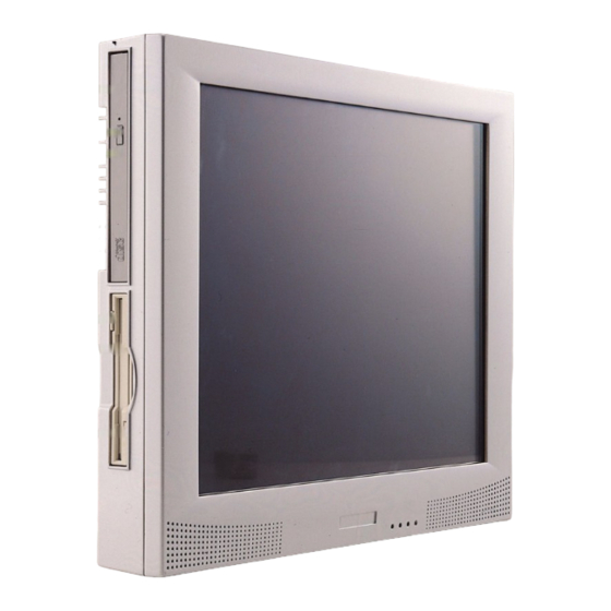
When you look at the left side of the panel PC, you will see the floppy disk drive, CD-ROM drive and PCMCIA expansion sockets, as shown in Fig. 2-2. • Compact CD-ROM drive CD-ROM eject button • • CD-ROM drive activity light •... -
Page 22: Figure 2.3:Rear View Of The Panel Pc
USB ports PS2 port Line-out jack COM2 VGA port Ethernet Mic-in Line-in Jack jack jack Figure 2.4: Rear and bottom view of the panel PC Figure 2-4 shows the I/O section and power switch of the panel PC. PPC-S154T User’s Manual... -
Page 23: Installation Procedures
2.2 Installation Procedures 2.2.1 Connecting the power cord The panel PC can only be powered by a DC electrical outlet (16Vdc~25Vdc, 3.5A max.). Be sure to always handle the power cords by holding the plug ends only. Please follow the figure 2-5 to connect the male plug of the power cord to the DC inlet of the panel PC. -
Page 24: Figure 2.6:Power Switch In Lock Status
Power switch (Lock status) Figure 2.6: Power switch in lock status Power switch (Open status) Figure 2.7: Power switch in open status PPC-S154T User’s Manual... -
Page 25: Running The Bios Setup Program
2.3 Running the BIOS Setup Program Your panel PC is likely to have been properly set up and configured by your dealer prior to delivery. You may still find it necessary to use the panel PC's BIOS (Basic Input-Output System) setup program to change system configuration information, such as the current date and time or your type of hard drive. -
Page 26: Installing System Software
If you are presented with an operating system command prompt, such as A:\>, then you must partition and format your hard drive, and manually copy the operating system files to it. Refer to your operating system user's manual for instructions on partitioning and formatting a hard drive. PPC-S154T User’s Manual... -
Page 27: Installing The Drivers
These files are a very useful supplement to the information in this man- ual. Note: The drivers and utilities used for the PPC-S154T panel PCs are subject to change without notice. If in doubt, check Advantech's website or contact our application engineers for the latest information regarding drivers and utlities. - Page 28 PPC-S154T User’s Manual...
- Page 29 Hardware and Peripheral Installation This chapter details the installation of the PPC-S154T panel PC hardware. Sections include: • Overview of Hardware Installation and Upgrading • Installing the 2.5" Hard Disk Drive (HDD) • Installing the Central Processing Unit (CPU) and SDRAM Memory Module...
-
Page 30: Chapter 3 Hardware And Peripheral Installation
Pin 1 on the connector, which is labelled on the board. Plug the other end of the cable into the HDD, with Pin 1 on the cable corresponding to Pin 1 on the HDD. PPC-S154T User’s Manual... -
Page 31: Figure 3.1:Install The Hdd On The Hdd Bracke
Put the HDD bracket with HDD back to original position, then screw the four screws to fix it. Figure 3.1: Install the HDD on the HDD bracke Figure 3.2: Connect HDD to the HDD cable Chapter 3... -
Page 32: Installing The Sdram Memory Module And Central Processing Unit (Cpu)
Unscrew the screw on the right side for CPU and heat sink cover, slide leftwrad and detach the cover, then you can find one 478-pin CPU socket and one 200-pin SODIMM socket (DIMM1). Figure 3.3: Detaching the CPU plastic cover and heat sink PPC-S154T User’s Manual... -
Page 33: Figure 3.4:Cpu With Thermal Pad
Locate the ZIF socket and open it by first pulling the lever side ways away from the socket, then upwards at an angle of 90 degrees. Insert the CPU with the correct orientation Slide the CPU in gently. It should insert easily. If not, pull the lever up a little more and make sure the pins of the CPU correspond with the holes of the socket. - Page 34 Finally, put the heatsink with the fan back and tighten the four screws, then put back and fix the plasticcover. PPC-S154T User’s Manual...
- Page 35 Jumper Settings and Connectors This chapter tells how to set up the panel PC hardware, including instruc- tions on setting jumpers and connecting peripherals, switches and indicators. Be sure to read all the safety precautions before you begin the installation proce- dures.
-
Page 36: Chapter 4 Jumper Settings And Connectors
A pair of needle-nose pliers may be helpful when working with jumpers. If you have any doubts about the best hardware configuration for your application, contact your local distributor or sales representative before you make any changes. PPC-S154T User’s Manual... -
Page 37: Jumpers And Switch
Label Function LCD power connector CMOS clear for external RTC COM2 RS232/422/485 setting COM1 / COM2/ COM3 ping 9 output type setting Panel type setting 4.1.2 Locating jumpers and switch Figure 4.1: Locating jumpers on the PPC-S154T motherboard Chapter 4... -
Page 38: Installing The 2.5" Hard Disk Drive (Hdd)
COM 3 connector CN13 Touch screen sensor connector CN16 Speaker-out connector CN18 2.5 " IDE connector CN19 Slim type CD-ROM/IDE connector CN25 Panel control connector CN26 SIR connector FAN1 CPU fan power connector FAN2 System fan power connector PPC-S154T User’s Manual... -
Page 39: Locating Connectors
DIMM 1 DIMM 2 CN19 CN18 FAN2 CN26 CN13 CN25 CN16 CN11 CN12 Figure 4.2: Locating connectors on the PPC-S154T motherboard 4.2 CPU Installation You can install an Intel® Pentium®-M CPU without setting any fre- quency ratio or voltage. Chapter 4... -
Page 40: Cmos Clear For External Rtc (Jp3)
422/485 (in one COM port connector) 4.4.1 COM2 RS-232/422/485 setting (JP4) COM2 can be configured to operate in RS-232, RS-422, or RS-485 mode. This is done via J4 settings. Table 4.4: COM2 RS-232/422/485 setting (JP4) *RS-232 * default setting PPC-S154T User’s Manual... -
Page 41: Table 4.5:Com2 Rs-232/422/485 Setting (Jp4)
Table 4.5: COM2 RS-232/422/485 setting (JP4) RS-422 * default setting Table 4.6: COM2 RS-232/422/485 setting (J4) RS-485 * default setting The IRQ and the address ranges for COM1 and 2 are fixed. However, if you wish to disable the port or change these parameters later you can do this in the system BIOS setup. -
Page 42: Com1/Com2/Com3/ Pin 9 Output Setting (Jp5)
LCD displays. The board has two connectors to support these displays simultaneously: one for standard CRT VGA monitors, and one for flat panel displays. Pin assignments for the flat panel display connector, backlight connector and other related connectors are shown in Appendix C. PPC-S154T User’s Manual... -
Page 43: Lcd Panel Power Setting
SW1 is a 8-pin dip switch for selecting panel type and display mode. A 1024 x 768 TFT LCD is used in the PPC-S154T, so the switch is preset according to the table below. The switch is already defaulted for the PPC- S154T's LCD, so it should not be modified. - Page 44 PPC-S154T User’s Manual...
- Page 45 Intel Chipset This chapter provides information on Intel chipset configuration • Introduction • Installation of Intel INF driver -Installation of Intel IAA driver • Further information...
-
Page 46: Chapter 5 Intel Chipset
Chapter 5 Intel Chipset 5.1 Introduction The PPC-S154T uses the combination of Intel 845GV north bridge and Intel 82801 DB ICH4 south bridge. The Intel® 845GV chipset is an innovative integrated graphics chipset developed with DDR266 memory and optimized to support the Intel Pen- tium®... -
Page 47: Further Information
Path: D:\PPC-S154\Chipset Software\IAA Drivers\2.3\iaa23_multi Press "Next "to proceed, and press "Finish". Choose "Yes, I want to restart my computer", and press "Finish", the system will reboot automatally 5.2 Further Information Intel website: http://www.intel.com Advantech websites: www.advantech.com www.advantech.com.tw Chapter 5... - Page 48 PPC-S154T User’s Manual...
- Page 49 AGP SVGA Setup • Introduction • Installation of SVGA Driver for Windows 98 for Windows 2000/XP • Further Information...
-
Page 50: Chapter 6 Agp Svga Setup
Chapter 6 AGP SVGA Setup 6.1 Introduction The PPC-S154T has an on board integrated VGA chipset The specifica- tions and features are described as follows: 6.1.1 Chipset The PPC-S154T uses a integrated graphics chipset in Intel 845GV chipset . The Intel 845GV chipset contains an entirely new 32bpp graphics hard- ware engine, known as Intel Extreme Graphics, which has been designed and built by Intel to optimize the performance of the Intel Processor. -
Page 51: Installation For Windows 98
'Next' to continue. Read License Agreement and click "Yes" to proceed. When the 'Setup COMPLETE' message appears click 'Finish' to restart PPC-S154T. After the system reboot, the screen show "Insert Disk", click "OK" click "browse" Find the folder as following : D:\PPC-S154\845GV Graphics Driver\win9x_me\win9x, click "OK"... -
Page 52: Further Information
6.3 Further Information For further information about the AGP/SVGA installation in your PPC- S154T, including driver updates, troubleshooting guides and FAQ lists, visit the following web resources: Intel support website: http://downloadfinder.intel.com Advantech websites:www.advantech.com www.advantech.com.tw PPC-S154T User’s Manual... - Page 53 PCI Bus Ethernet Interface This chapter provides information on Ethernet configuration. • Introduction • Installation of Ethernet Driver - for Windows 98 - for Windows 2000/XP • Further Information...
-
Page 54: Chapter 7 Pci Bus Ethernet Interface
7.2 Installation of Ethernet Driver Before installing the Ethernet driver, note the procedures below. You must know which operating system you are using in your PPC-S154T, and then refer to the corresponding installation flow chart. Then just fol- low the steps described in the flow chart. You will quickly and success- fully complete the installation, even if you are not familiar with instructions for Windows. -
Page 55: Installation For Windows 98/Nt/Me/2000
7.2.1 Installation for Windows 98/NT/ME/2000 Upon installing on Windows 98, the system will automatically detect the Ethernet hardware and install the Ethernet driver. It is recommended that you upgrade to the Intel driver as following : a Select "Start", "Settings", "Control Panel", "System" b. -
Page 56: Further Information
7.3 Further Information Intel website : - Main Intel web support site: http://support.intel.com - Network products information: http://www.intel.com/network Advantech websites: www.advantech.com www.advantech.com.tw PPC-S154T User’s Manual... - Page 57 Audio • Introduction • Installation of Audio Driver...
-
Page 58: Chapter 8 Audio
8.2 Installation of Audio Driver Before installing the audio driver, please take note of the procedures detailed below. You must know which operating system you are using in your PPC-S154T, and then refer to the corresponding installation proce- dure. Important: The following are examples only. -
Page 59: Usb 2.0
USB 2.0 This chapter describes how to install USB 2.0 driver... -
Page 60: Chapter 9 Usb 2.0
9.1 Installation of USB 2.0 driver Before installing the audio driver, please take note of the procedures detailed below. You must know which operating system you are using in your PPC-S154T, and then refer to the corresponding installation proce- dure Important : The following windows illustrations are exam- ples only. - Page 61 Touchscreen • Introduction • Installation of Touchscreen Drivers for Windows 98/ME for Windows 2000/XP...
-
Page 62: Chapter 10 Touchscreen
For more detailed information, please visit the following websites: www.dynapro.com www.3m.com/us/electronics_mfg/touch_systems www.elotouch.com Advantech Co.,Ltd. reserves the right to alter the touchscreen at any time without notice. 10.1.2 General specifications Please refer to Chapter 1, Section 1.2 of this manual. 10.1.3 Environmental specifications Temperature:-10°... -
Page 63: Installation Of Touchscreen Drivers
10.2.1 Installation for Windows 98/ME To install the software to PPC-S154T, your PPC-S154T must have Win- dows 98/Me system running and installed PenMount Series Interface control board already. If you have an older version of PenMount Win- dows 98/Me driver installed in your PPC-S154T, please remove it first. -
Page 64: Installation For Windows 2000/Xp
"OK" 10.2.2 Installation for Windows 2000/XP To install the software to PPC-S154T, your PPC-S154T must have Win- dows 2000/XP system running and installed PenMount Series Interface control board already. If you have an older version of PenMount Win- dows 2000/XP driver installed in your PPC-S154T, please remove it first. -
Page 65: Further Information
The next screen is "Hardware Installation" , select " Continue Anyway" The next screen is "InstallShield Wizard Completed", Select "Finish" 10.3 Further Information Dynapro website: www.dynapro.com www.3m.com/us/electronics_mfg/touch_systems Advantech websites: www.advantech.com www.advantech.com.tw Salt website: www.salt.com.tw Chapter 10... - Page 66 PPC-S154T User’s Manual...
-
Page 67: Watchdog Timer
Programming the Watchdog Timer The PPC-S154T is equipped with a watchdog timer that resets the CPU or generates an interrupt if processing comes to a standstill for any reason. This feature ensures system reliability in industrial standalone or unmanned environments. -
Page 68: Appendix A Programming The Watchdog Timer
I/O port 440 (hex). The following example shows how you might program the watchdog timer : ;----------------------------------------------------------------------------------- ; Enter the extended function mode , interruptible double-write | ;----------------------------------------------------------------------------------- MOV DX,2EH MOV AL,87H OUT DX,AL OUT DX,AL PPC-S154T User’s Manual... - Page 69 ;----------------------------------------------------------------------------- ; Configurate logical device 8, configuration register CRF6 | ;----------------------------------------------------------------------------- MOV DX,2EH MOV AL,07H ; point to Logical Device Number Reg. OUT DX,AL MOV DX,2FH MOV AL,08H ; select logical device 8 OUT DX,AL MOV DX,2EH MOV AL,30H ;Set watch dog activate or inactivate OUT DX,AL MOV DX,2FH MOV AL,01H ;...
- Page 70 OUT DX,AL ;------------------------------------------ ; Exit extended function mode | ;------------------------------------------ MOV DX,2EH MOV AL,AAH PPC-S154T User’s Manual...
- Page 71 Pin Assignments...
-
Page 72: Appendix B Pin Assignments
Table B.1: Inverter power connector (CN4) Signal +24V ENABKL Brightness Adj. +5 V B.2 Internal Speaker Connector (CN15) Table B.2: Internal speaker connector (CN15) Signal Speaker out_R - Speaker out_R + Speaker out_L + Speaker out_L - PPC-S154T User’s Manual... -
Page 73: Floppy Drive Connector (Cn9)
B.3 Floppy Drive Connector (CN9) Table B.3: Floppy drive connector (CN9) Signal Signal VCC (+5 V) STEP INDEX VCC (+5 V) WRITE ENABLE DRIVE SELECT VCC (+5 V) WRITE DATA DISK CHANGE TRACK 0 WRITE PRO- TECT MOTOR ON READ DATA DIRECTION DENSITY SIDE 1... -
Page 74: Ide Hard Disk Drive Connector (Cn18)
SIGNAL GND HDD DREQ IO WRITE IO READ HD READY CABLE SELECT HDACK 0 # IRQ14 ADDR 1 ADDR 0 ADDR 2 HDD SELECT 0 # 38 HDD SELECT 1 # IDE ACTIVE 0 # # low active PPC-S154T User’s Manual... -
Page 75: Cd-Rom Connector (Cn19)
B.5 CD-ROM Connector (CN19) Table B.5: CD-ROM connector (CN19) Signal Signal Audio_L Audio_R IDE RESET # DATA8 DATA7 DATA9 DATA6 DATA10 DATA5 DATA11 DATA4 DATA12 DATA3 DATA13 DATA2 DATA14 DATA1 DATA15 DATA0 HDD DREQ IO READ IO WRITE HD READY HD ACK 0 # IRQ 15 ADDR1... -
Page 76: Touch Screen Sensor Connector (Cn13)
B.6 Touch Screen Sensor Connector (CN13) Table B.6: Touch Screen Sensor Connector (CN13) Signal B.7 IR Connector (CN26) Table B.7: IR connector (CN26) Signal IR_IN IR_OUT PPC-S154T User’s Manual... -
Page 77: Cpu Fan Power Connector (Fan1)
B.8 CPU Fan Power Connector (FAN1) Table B.8: CPU fan power connector (FAN1) Signal +5 V FAN_DET B.9 System Fan Power Connector (FAN2) Table B.9: Fan power connector (FAN2) Signal +5 V FAN_DET Appendix B... -
Page 78: Flat Panel Display Connector (Cn3)
B.10 Flat Panel Display Connector (CN3) Table B.10: Flat Panel Display Connector (CN3) VDD(3.3V) VDD(3.3V) RXIN0- RXIN0+ RXIN1- RXIN1+ RXIN2- RXIN2+ CLK- LCK+ RXIN3- RXIN3+ PPC-S154T User’s Manual... -
Page 79: Flat Panel Display Connector (Cn5)
B.11 Flat Panel Display Connector (CN5) Table B.11: Flat Panel Display Connector (CN5) VDD(3.3V) VDD(3.3V) RXIN0- RXIN0+ RXIN1- RXIN1+ RXIN2- RXIN2+ CLK- LCK+ RXIN3- RXIN3+ Appendix B... -
Page 80: Com1
B.12 COM1 Table B.12: COM1 Signal PPC-S154T User’s Manual... -
Page 81: Com2
B.13 COM2 Table B.13: COM2 Signal RS-232 RS-422 RS-485 DATA- DATA+ Appendix B... -
Page 82: Com3
B.14 COM3 Table B.14: COM1 Signal PPC-S154T User’s Manual... -
Page 83: B.15 14 Vga Connector (Cn2)
B.15 14 VGA connector (CN2) Table B.15: VGA connector (CN2) Signal Signal VGA G VGA H GREEN VGA G VGA G VGA V BLUE VGA G DDCSCL VGA G DDCSDA B.16 Parallel Port Connector (CN8)(Reserved) Table B.16: Parallel Port Connector (CN8) Signal Signal STROBE*... -
Page 84: B.17 Tv Out (S-Video) Connector (Reserved)(Cn6)
B.17 TV OUT (S-VIDEO) connector (Reserved)(CN6) Table B.17: TV OUT (S-VIDEO) connector (Reserved)(CN6) Signal TV_Y TV_C B.18 PS/2 Keyboard & mouse port (CN14) Table B.18: PS/2 Keyboard & mouse port(CN14) Signal KB_DTA MS_DTA LB_CLK MS_CLK PPC-S154T User’s Manual...
Need help?
Do you have a question about the PPC-S154T and is the answer not in the manual?
Questions and answers
Как переключить на русский язык?