
Related Manuals for Trane GECA -006


Summary of Contents for Trane GECA -006
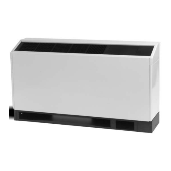
- Page 1 Installation Owner Diagnostics Axiom Console Configuration Water-Source Comfort System Model GEC Models “A” and later Design Sequence 60 HZ: GECA -006, -009, -012, -015, -018 50 HZ: GECA -006, -009, -012, -015 GECA-SVX01B-EN...
-
Page 2: General Information
General Information Introduction The GECA water-source comfort system contains standard features to enhance performance, serviceability and extend life of the equipment. Several of these features are shown below: WATER REGULATING CONNECTION WARNINGS / CAUTIONS EXPLANATION: CAUTION WARNING Cautions are provided throughout this Warnings are provided throughout manual to indicate to installing this manual to indicate to installing... -
Page 3: Table Of Contents
Contents Installation/Startup/Commissioning General Information Pre-installation Checklist Dimensions/Weights Installation Instructions Electrical Requirements Pre-Startup Checklist Startup/Commissioning Sequence of Operation Startup Checklist & Log Maintenance Warranty Information Troubleshooting Checklist Unit Wiring GECA-SVX01B-EN... -
Page 4: Pre-Installation Checklist
Pre-installation Checklist has been determined to be a Jobsite Inspection Jobsite Storage cause of odors and serious Each unit has been inspected, tested This unit is intended for indoor use health related indoor air quality and operated at the factory by pro- only. -
Page 5: Dimensions/Weights
Dimensions/ Weights Unit Clearance Access to the unit for servicing purposes should be provided at installation. All configurations require clear- ance from other mechanical and electrical equipment on three service sides (shown below). This enables panel removal from the unit for service/maintenance ability. Unit without Pallet with Pallet... - Page 6 Dimensions/Weights Cabinet (RH) no Pump Kit GECA-SVX01B-EN...
- Page 7 Dimensions/Weights Subbase (RH) no Pump Kit GECA-SVX01B-EN...
- Page 8 Dimensions/Weights Cabinet (LH) no Pump Kit GECA-SVX01B-EN...
- Page 9 Dimensions/Weights Subbase (LH) no Pump Kit GECA-SVX01B-EN...
- Page 10 Dimensions/Weights Cabinet (RH) Extended Length GECA-SVX01B-EN...
- Page 11 Dimensions/Weights Subbase (RH) Extended Length GECA-SVX01B-EN...
- Page 12 Dimensions/Weights Cabinet (LH) Extended Length GECA-SVX01B-EN...
- Page 13 Dimensions/Weights Subbase (LH) Extended Length GECA-SVX01B-EN...
- Page 14 Dimensions/Weights Cabinet (RH) Low Height Unit GECA-SVX01B-EN...
- Page 15 Dimensions/Weights Cabinet (LH) Low Height Unit GECA-SVX01B-EN...
- Page 16 Dimensions/Weights Chassis (RH) GECA-SVX01B-EN...
- Page 17 Dimensions/Weights Chassis (LH) GECA-SVX01B-EN...
- Page 18 Dimensions/Weights Pump Kit Option GECA-SVX01B-EN...
-
Page 19: Installation Instructions
Installation Instructions CHASSIS REFRIGERATION FRONT PANEL Uncrate Unit Inspect Unit Remove packaging and inspect the unit. Carefully re- Remove refrigeration panel and inspect the unit. Be move the stretch wrap and cardboard pieces. The in- stallation literature and Torx ® head tool may be found certain the refrigerant tubing has clearance from adja- cent parts. - Page 20 Installation Instructions Mounting of Disconnect (receptical box-OPTION) Wall Flange Mounting of the receptical box should be made prior After removing chassis from the subbase, install the to piping and electrical hook-up. This factory discon- wall flange assembly to the desired wall with the use nect option is designed to fit inside the end pocket.
- Page 21 Slide the chassis onto the subbase to verify that field out pipe. Trane recommends a 1/2-inch x 3/4-inch installed disconnects, condensate pipe, and supply/ nominal ell to be field brazed to the factory 1/2" nomi- return pipe are in the appropriate locations and will nal water-in/out lines.
- Page 22 For units containing a field pro- vided disconnect, or, are hard wired to the unit, Trane provides pig tail leads inside a 2 x 4 handy-box in either the right or left side end pocket. See unit wiring schematic for details.
- Page 23 Installation Instructions Thermostat Location Location of the thermostat or zone sensor is an important element of effective room control. Areas where the thermostat/zone sensor should not be mounted include: Behind doors or corners; Near hot or cold air ducts; Near radiant heat (heat emitted from appli- ances or sun);...
- Page 24 Installation Instructions Receptacle Plug (Option) For units with the factory provided disconnect op- tions, the receptacle plug may now be connected to the electrical outlet. UNIT FRONT Factory Installed Pump Kit (Option) All wiring to the pump kit option is factory made. NO FIELD wiring will be required. Field hook-up to the sys- tem water loop is made at the bottom of the pump box.
- Page 25 Trane stat or sensor options. The more information on the recommends a few accessory con- low voltage connection is types of hose kits Trane rec- siderations to the system installa- factory made if unit mount- ommends, review the HKTA- tion.
- Page 26 Installation Instructions Table M-1: Physical Data (GECA 006-012) 60 HZ - 009 60 HZ - 012 Model: GECA 006-012 60 HZ - 006 50 HZ - 006 50 HZ - 009 Length of cabinet (in) 48 or 63 48 or 63 48 or 63 Height (in) 25 or 22 1/2...
-
Page 27: Electrical Requirements
Electrical Requirements Units w/o Pump Kit Table E-1: GECA electrical performance Model No. Volts Total Comp. Comp. No. of Blower Blower Minimum Overcurrent Electric Heat GECA Compres. Motor Motor Motor Circuit Protective SIZE Amps (ea) (ea) Ampacity Device 115/60/1 36.2 0.90 1/20 None... - Page 28 Electrical Requirements Units w/ Pump Kit Table E-2: GECA electrical performance Model No. Volts Total Comp. Comp. No. of Blower Blower Minimum Overcurrent Electric Heat GECA Compr. Motor Motor Motor Circuit Protective SIZE Amps 60 HZ (ea) (ea) Ampacity Device 230/60/1 2.76 17.7...
-
Page 29: Pre-Startup Checklist
Pre-Startup Checklist Pre-Startup Checklist Before energizing the unit, the following system devices must be checked: Is the high voltage power supply correct and in accordance with the nameplate ratings? Is phasing of the unit correct per compressor rotation (scroll compressor only)? Is the field wiring and circuit protection the correct size? Is the low voltage control circuit wiring correct per the unit wiring diagram? Is the piping system clean/complete and correct? (A recommendation of all system flushing of debris from... -
Page 30: Sequence Of Operation
Sequence of Operation Initial Unit Start-up Note: Start-up for the Tracer ZN510 Controller may be found in WSHP-IOP-2. Start-up with the conventional thermostat is included below: 1.Set the thermostat to the highest position. 2.Set the thermostat system switch to COOL with the fan control to AUTO. The compres- sor should NOT run. - Page 31 Sequence of Operation Operating Pressures GENERAL: There are many variables (airflow, air temperatures) in an air conditioning system that will affect operating refrigerant pressures and temperatures. The charts below shows approximate conditions and is based on air flow at the rated SCFM, entering air at 80.6 °F(DB), 66.2 °F(WB) in cooling, 68 °F(DB) in heating. (+)Heating data with 35 °F EWT is based on the use of an anti-freeze solution having a freezing point 20 °F lower than the minimum expected entering temperature.
- Page 32 Sequence of Operation Operating Data Model Entering Water Cooling Heating Suction Pres- Discharge Water Air Temp Suction Discharge Water Temp Air Temp GEVA Water Temp, Flow sure, Pressure, Temp Rise Drop Pressure Pressure Drop Rise °F PSIG PSIG °F °F DB PSIG PSIG °F...
- Page 33 Sequence of Operation Water Pressure Drop Tables 2 and 3 should be used to define feet of head/pressure drop. Please note the feet of pressure (ft/head) provided is at ARI/ISO standard. Note: To calculate feet of head, when using gauges that read in PSIG, multiply PSI by 2.31. Table 2: Cooling water pressure drops Table 3: Heating water pressure drops (WPD) in feet of head...
-
Page 34: Startup Checklist & Log
Startup Checklist and Log Installing Contractor: Use this form to thoroughly check-out the system and units before and during start-up. (This form need not be returned to the factory unless requested during technical service support). Job Name: Model Number: Date: Serial Number: In order to minimize troubleshooting and costly system failures, complete the following checks and data entries before the system is put into full operation. -
Page 35: Maintenance
Maintenance For units on well water, it is im- Preventive Maintenance portant to check the cleanliness Maintenance on the unit is simplified of the water-to-refrigerant heat with the following preventive sugges- exchanger. Should it become tions: contaminated with dirt and scal- Filter maintenance must be per- ing as a result of bad water, the formed to assure proper opera-... - Page 36 Maintenance Filter Replacement (standard height configuration) Filter replacement is done at the front return-air opening of the console unit. No tools are required for the replace- ment. The maintenence process is done via a 3-STEP process (See Figure 2 for filter replacement): STEP 1: Through the return-air opening, slide filter to the back of the con-...
-
Page 37: Warranty Information
Information Warranty Information Standard Warranty The standard water-source heat pump warranty is The Trane Company parts-only warranty, running 12 months from startup, not to exceed 18-months from shipment. Extended Warranty The optional extended warranty is a second through fifth year warranty. The time starts at the end of the standard 1- year coverage through the fifth year. -
Page 38: Troubleshooting Checklist
Troubleshooting Checklist Problem Heating Cooling Cause Correction Main power off Check fuses Defective control transformer Replace No response to any Broken or loose connection Repair thermostat setting Defective thermostat Replace Transformer Reset Transformer Thermostat or sensor improperly located Relocate Unit short cycles Change jumper on thermostat from 2- Unit contains unit mounted thermostat degrees to 4-degrees... - Page 39 Troubleshooting Checklist Deluxe Controls Table 6: Diagnostic LED’s Troubleshooting equipment contain- Color: Green Color: Red Controller Mode ing the Deluxe Control option may be LED1 LED2 LED3 Control OFF made easy by using the three LED’s Normal/Compressor OFF (light emitting diodes). These LED’s FLASH Anti-short cycle are provided for indicating the oper-...
-
Page 40: Unit Wiring
Unit Wiring Basic 115V/60 HZ/1 PH GECA-SVX01B-EN... - Page 41 Unit Wiring Basic 220-240V/50 HZ/1 PH GECA-SVX01B-EN...
- Page 42 Unit Wiring Deluxe 230V/60 HZ/1 PH GECA-SVX01B-EN...
- Page 43 Unit Wiring Deluxe 220-240V/50 HZ/1 PH GECA-SVX01B-EN...
- Page 44 Unit Wiring Tracer ZN510 265V/60 HZ/1 PH GECA-SVX01B-EN...
- Page 45 Unit Wiring Tracer ZN510 220-240V/50 HZ/1 PH GECA-SVX01B-EN...
-
Page 46: Geca-Svx01B-En
Inland A business of American Standard Companies www.trane.com Trane has a policy of continuous product and data improvement and reserves the right to change For more information, contact your local district design and specifications without notice. office or e-mail us at comfort@trane.com...
Need help?
Do you have a question about the GECA -006 and is the answer not in the manual?
Questions and answers