Advertisement
Quick Links
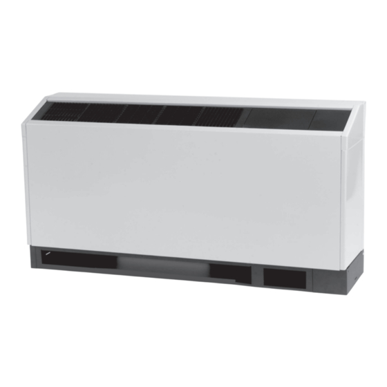
Installation, Operation, and Maintenance
Water Source Heat Pump Axiom™
High Efficiency Console
0.5 to 1.5 Tons — 60 Hz
Model Numbers:
GEC* 006, 009, 012, 015, 018 (60 Hz)
Only qualified personnel should install and service the equipment. The installation, starting up, and servicing of heating, ventilating, and air-conditioning equipment
can be hazardous and requires specific knowledge and training. Improperly installed, adjusted or altered equipment by an unqualified person could result in death or
serious injury. When working on the equipment, observe all precautions in the literature and on the tags, stickers, and labels that are attached to the equipment.
December 2024
SAFETY WARNING
WSHP-SVX022A-EN
Advertisement

Related Manuals for Trane GECK006


Summary of Contents for Trane GECK006
- Page 1 Installation, Operation, and Maintenance Water Source Heat Pump Axiom™ High Efficiency Console 0.5 to 1.5 Tons — 60 Hz Model Numbers: GEC* 006, 009, 012, 015, 018 (60 Hz) SAFETY WARNING Only qualified personnel should install and service the equipment. The installation, starting up, and servicing of heating, ventilating, and air-conditioning equipment can be hazardous and requires specific knowledge and training.
- Page 2 (HCFCs). Not all refrigerants containing these compounds bump cap, fall protection, electrical PPE and arc have the same potential impact to the environment. Trane flash clothing). ALWAYS refer to appropriate advocates the responsible handling of all refrigerants.
- Page 3 This document and the information in it are the property of regulations are more stringent than these Trane, and may not be used or reproduced in whole or in policies, those regulations supersede these part without written permission. Trane reserves the right to policies.
- Page 4 Table of Contents Model Number Description ....5 Electrical Data ......30 General Information .
- Page 5 Model Number Description Digit 1, 2, 3 — Unit Configuration Digit 15 — Supply-Air Arrangement Digit 24 — Filter Type GEC = High Efficiency Console 0 = Standard Supply-Air Arrangement 0 = No Filter; Chassis Only 1 = 1-inch Throwaway Filter A = 1-inch MERV 8 Filter Digit 4 —...
- Page 6 General Information Jobsite Inspection Job Storage Each unit has been inspected, tested and operated at the NOTICE factory by production and quality associates prior to being Microbial Growth! crated for safe transit. However, rough handling or accidents can occur resulting in damaged equipment being Failure to follow instructions below could result in odors and damage to the equipment and building delivered.
- Page 7 General Information Operating Limits Table 1. Operating limits Operating Limits Cooling Heating Air Limits 45°F (7°C) Min. ambient air DB 130°F (54.4°C) Max. ambient air DB 65.6/49.4°F (18.7/9.7°C) 53.0°F/- (11.7°C/-) Min. EAT DB/WB 85.6/77.1°F (29.8/25.1°C) 83.0°F/- (28.3°C/-) Max. EAT DB/WB Airflow range 307 to 580 CFM/ton Water Limits...
- Page 8 Unit Dimensions Service Clearances from other mechanical and electrical equipment on three service sides (shown below). This enables panel removal Access to the unit for servicing purposes should be from the unit for service/maintenance ability. provided at installation. All configurations require clearance Figure 2.
- Page 9 Unit Dimensions Figure 4. GEC 0.5 to 1.5 tons (60 Hz) - cabinet (LH) piping connection SUPPLY AIR GRILLE 48" 12" BACK UNIT PIPE & ELEC. FIELD HOOK-UP 4" 9 5/8" TOP VIEW 3/4" 3/4" 4 3/8" 3 3/8" 7/8" RECEPTACLE BOX WATER IN CONN.
- Page 10 Unit Dimensions Figure 5. GEC 0.5 to 1.5 tons (60 Hz) - subbase (RH) 48" 3/4" 4 3/4" TOP VIEW 9 1/4" 15" 33" ISO VIEW 6" WSHP-SVX022A-EN...
- Page 11 Unit Dimensions Figure 6. GEC 0.5 to 1.5 tons (60 Hz) - subbase (LH) 48" 3/4" 4 3/4" TOP VIEW 15" 6" 13 1/4" 33" ISO VIEW WSHP-SVX022A-EN...
- Page 12 Unit Dimensions Figure 7. GEC 0.5 to 1.5 tons (60 Hz) - cabinet (RH) piping extended length 63" BACK OF UNIT 12" PIPE & ELEC. FIELD HOOK-UP. SUPPLY AIR GRILLE 1" 18 7/8" 9 1/4" TOP VIEW 1" 4 3/8" RECEPTACLE BOX 7/8"...
- Page 13 Unit Dimensions Figure 8. GEC 0.5 to 1.5 tons (60 Hz) - cabinet (LH) piping extended length 63" SUPPLY AIR GRILLE BACK OF UNIT 12" PIPE & ELEC. FIELD HOOK-UP 8 3/4" TOP VIEW 9 1/4" 3/4" 3/4" 4 3/8" 7/8"...
- Page 14 Unit Dimensions Figure 9. GEC 0.5 to 1.5 tons (60 Hz) - subbase (RH) extended length 63" 3/4" 19 3/4" TOP VIEW 9 1/4" 15" 33" ISO VIEW 6" WSHP-SVX022A-EN...
- Page 15 Unit Dimensions Figure 10. GEC 0.5 to 1.5 tons (60 Hz) - subbase (LH) extended length 63" 3/4" 19 3/4" TOP VIEW 15" 6" 28" 33" ISO VIEW WSHP-SVX022A-EN...
- Page 16 Unit Dimensions Figure 11. GEC 0.5 to 1.5 tons (60 Hz) - cabinet (RH) low height unit 48" 12" BACK OF UNIT FIELD ADJUSTABLE BI-DIRECTIONAL GRILLES PIPE & ELECTRICAL 3/4" FIELD HOOK-UP 4" 9 5/8" TOP VIEW 3/4" 4 3/8" 7/8"...
- Page 17 Unit Dimensions Figure 12. GEC 0.5 to 1.5 tons (60 Hz) - cabinet (LH) low height unit FIELD ADJUSTABLE BI-DIRECTIONAL GRILLES 48" 12" BACK OF UNIT PIPE & ELEC. FIELD HOOK-UP 4" 9 5/8" TOP VIEW 3/4" 3/4" 4 3/8" 7/8"...
- Page 18 Unit Dimensions Figure 13. GEC 0.5 to 1.5 tons (60 Hz) - chassis + low height factory configuration (RH) 48" 42-1/4" 11 1/4" 11 1/2" TOP VIEW CONTROL BOX SERVICE PANEL 2-1/8" WATER OUT 3" .625 ODS. 1 1/2" 7/8? CUT OUT FOR 3/4"...
- Page 19 Unit Dimensions Figure 14. GEC 0.5 to 1.5 tons (60 Hz) - chassis + standard factory configuration (RH) 48'' 42 1/4'' 11 1/2'' CONTROL BOX TOP VIEW SERVICE PANEL AIR SIDE REFRIGERATION 2 1/8'' SERVICE PANEL SERVICE PANEL 1 7/8'' 1 1/2'' WATER OUT CUT OUT FOR...
- Page 20 Unit Dimensions Figure 15. GEC 0.5 to 1.5 tons (60 Hz) – chassis + low height factory configuration (LH) 48" 42-1/4" 11 1/2" 11 1/4" TOP VIEW CONTROL BOX SERVICE PANEL 1 7/8" 3" 2-1/8" CUT OUT FOR 1 3/8" 3/4"...
- Page 21 Unit Dimensions Figure 16. GEC 0.5 to 1.5 tons (60 Hz) – chassis + standard factory configuration (LH) 48'' 42 1/4'' 11 1/2'' CONTROL BOX TOP VIEW SERVICE PANEL 2 1/8'' 1 7/8'' 1 3/8'' AIR SIDE SERVICE PANEL 3/4'' CUT OUT FOR WATER IN LOW VOLTAGE...
- Page 22 Weights Table 2. Unit weights GEC (0.5 to 1.5 tons) Shipping Weight with Pallet Shipping Weight without Pallet Unit Size Chassis + low Chassis + low height Chassis + standard Chassis + standard Unit Weight (lbs) Unit Weight (lbs) height subbase subbase (lbs) subbase (lbs) subbase (lbs)
- Page 23 • To be repaired only by trained service At all times, Trane’s maintenance and service guidelines shall be followed. If in doubt, contact Trane technical personnel. support for assistance. • Do not puncture refrigerant tubing.
- Page 24 • Verify continuity of earth bonding. 5. Continuously flush or purge with inert gas when using • Replace electrical components with Trane replacement flame to open circuit. parts, or those meeting the same ratings and qualified 6. Open the circuit.
- Page 25 A2L Information • Ensure that contamination of different refrigerants does 8. Do not overfill cylinders (no more than 80% volume not occur when using charging equipment. liquid charge). • Hoses or lines shall be as short as possible to minimize 9.
- Page 26 Table 3. Minimum room area Amin (GG. 7DV)(m Amin (GG. 7DV) (ft Models 0.6 meters height 1.94 feet height GECK006 GECK009 GECK012 GECK015 GECK018 Minimum Room Area (A ) Adjustments Multiply the altitude adjustment factor in the table below by...
- Page 27 A2L Information mechanical ventilation system meets the requirements of = 660 ft x 1.11 = 733 ft min.adj ANSI\ASHRAE Standard 15-2022, Section 7.6.4. No additional ventilation is required. Leak Detection System (Refrigerant charge greater than 3.91 lb Determining Room Area (A or TA) per circuit) The room area (A) is the room area enclosed by the projection to the floor of the walls, partitions, and doors of...
- Page 28 Installation WARNING flange assembly includes four,¼ in. diameter clearance holes. Hazardous Voltage! 5. Mounting of the receptacle box (option) should be Failure to disconnect power before servicing could made prior to piping and electrical hook-up. This factory result in death or serious injury. disconnect option is designed to fit inside the end Disconnect all electric power, including remote pocket.
- Page 29 9. Install the field provided water connections to the unit mounted controls. water-in/out pipe. Trane recommends a ½ in. x ¾ in. 14. The thermostat hook-up to the unit is made at the unit nominal ell to be field brazed to the factory ½ in.
- Page 30 Electrical Data Table 5. Electrical data (0.5 to 1.5 tons) Maximum Comp CompL Minimum Electric Total Blower No. of Blower Overcurrent Electric Circuit Heat Model Volts Unit Motor Comp Motor hp Motors Protective Heat kW (ea) (ea) Ampacity Amps Device GEC006 208/60/1 27.0...
- Page 31 Electrical Data Table 6. Console VA Deluxe with Deluxe with Electric Symbio™ 400-B (75 Designator x = ON Controls Reheat (75 VA) Heat (75 VA) Controller 12.5 Compressor Contactor Fan Relay Reversing Valve Reheat Valve — — Damper Actuator — —...
- Page 32 Pre-Start Checklist Before energizing the unit, the following system devices • Are the low/high-side pressure temperature caps must be checked: secure and in place? • Is the high voltage power supply correct and in • Are all the unit access panels secure and in place? accordance with the nameplate ratings? •...
- Page 33 Start-Up Initial Unit Start-up MODE Heat Cool Temperature differential Note: Start-up for wall-mounted thermostats found in thermostat manufacturer literature. Return-air temperature DB/WB Start-up with the conventional thermostat is included Supply-air temperature DB/WB below: Temperature differential 1. Set the thermostat to the highest position. 2.
- Page 34 Start-Up Table 7. Operating pressures in cooling/heating for GEC* units 60Hz Cooling Heating Entering Water Flow Suction Discharge Water Suction Discharge Air Temp Water Model Air Temp Water Temp (GPM) Pressure, Pressure, Temp Rise Pressure Pressure Rise Temp (°F) Drop (°F DB) Drop (°F) (psig) (psig)
- Page 35 Start-Up Table 7. Operating pressures in cooling/heating for GEC* units 60Hz (continued) Cooling Heating Entering Water Flow Suction Discharge Water Suction Discharge Air Temp Water Model Air Temp Water Temp (GPM) Pressure, Pressure, Temp Rise Pressure Pressure Rise Temp (°F) Drop (°F DB) Drop (°F) (psig)
- Page 36 Start-Up Table 8. Cooling water pressure drops (WPD) in feet of head for GEC* units - 0.5 to 1.5 tons Unit Size (60 Hz) EWT °F Ft. Pressure 14.0 11.7 Table 9. Heating water pressure drops (WPD) in feet of head for GEC* units - 0.5 to 1.5 tons Unit Size (60 Hz) EWT °F Ft.
- Page 37 Maintenance WARNING Table 12. Water quality Hazardous Service Procedures! Scaling Amount Failure to follow all precautions in this manual and on Calcium and magnesium (total hardness) Less than 350 ppm the tags, stickers, and labels could result in death or Corrosion serious injury.
- Page 38 Troubleshooting Deluxe 24V Controls WARNING Hazardous Service Procedures! Troubleshooting units which contain the deluxe 24V control option may be made easy by using the three LEDs (light Failure to follow all precautions in this manual and on emitting diodes). These LEDs are provided for indicating the tags, stickers, and labels could result in death or the operating mode of the controller.
- Page 39 Troubleshooting Table 14. Troubleshooting table (continued) Heating Cooling Cause Correction Problem Defective compressor overload Replace (if external) Defective compressor contactor Replace Blower runs, but compressor does not Supply Voltage too low Correct Defective compressor capacitor Replace Defective windings Replace Limit switches open Check cause/Replace or repair Heating Cooling...
- Page 40 Troubleshooting Table 14. Troubleshooting table (continued) Heating Cooling Cause Correction Problem Trash in heat exchanger Backflush Low water flow Increase GPM Overcharge of refrigerant Decrease charge Non-condensable in system Evacuate and recharge by weight High head pressure Water too hot Decrease temperature Dirty filter Clean / replace...
- Page 41 Wiring Diagrams Figure 17. Deluxe 24V controls WSHP-SVX022A-EN...
- Page 42 ARE SHOWN AT 25° C (77° F), AT TO 1TB2-3&4 IF USING ZONE SENSOR X13790886010. ATMOSPHERIC PRESSURE, AT 50% RELATIVE COMMUNICATION WIRE MUST BE TRANE PART NO. HUMIDITY, WITH ALL UTILITIES TURNED OFF, 400-20-28, OR WINDY CITY OR CONNECT AIR AND AFTER A NORMAL SHUTDOWN HAS "LEVEL 4"...
- Page 43 ARE SHOWN AT 25° C (77° F), AT TO 1TB2-3&4 IF USING ZONE SENSOR X13790886010. ATMOSPHERIC PRESSURE, AT 50% RELATIVE COMMUNICATION WIRE MUST BE TRANE PART NO. HUMIDITY, WITH ALL UTILITIES TURNED OFF, 400-20-28, OR WINDY CITY OR CONNECT AIR AND AFTER A NORMAL SHUTDOWN HAS "LEVEL 4"...
- Page 44 The time starts at the end of standard 1-year to exceed 18-months from shipment. There is a standard coverage through the fifth year. 5-year compressor warranty. These extended warranties apply only to new equipment installed in domestic Trane sales territories and must be ordered prior to start-up. WSHP-SVX022A-EN...
- Page 45 Notes WSHP-SVX022A-EN...
- Page 46 Notes WSHP-SVX022A-EN...
- Page 47 Notes WSHP-SVX022A-EN...
- Page 48 For more information, please visit trane.com or tranetechnologies.com. Trane has a policy of continuous product and product data improvements and reserves the right to change design and specifications without notice. We are committed to using environmentally conscious print practices.
Need help?
Do you have a question about the GECK006 and is the answer not in the manual?
Questions and answers