
Related Manuals for Trane GECA


Summary of Contents for Trane GECA
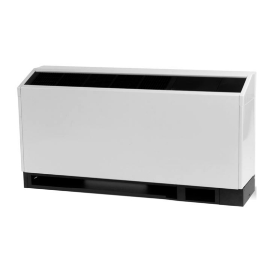
- Page 1 Trane Axiom ™ Water-Source Comfort System Standard Efficiency Console Model GECA (50 Hz) WSHP-PRC004-EN February 2001...
-
Page 2: Introduction
Introduction The design offers: Another Solution by Trane • Dual sloped plastic drain pan Trane has developed another system • solution to add to their exceptional Hot gas reheat (option) water-source product line. Introducing • Electric heat (option) ™ the Trane Axiom (Model GECA) water- •... -
Page 3: Table Of Contents
Contents Introduction Model Number Description General Data Features and Benefits Performance Data Sound Control Wiring Dimensional Data Accessories Mechanical Specifications WSHP-PRC004-EN... -
Page 4: Model Number Description
Model Number Description Water-Source Comfort System GEC A 012 6 1 A 0 1 1 0 0 0 D 0 1 0 N 0 0 1 0 0 1 L 000000 1-3 4 5-7 8 9 10 11 12 13 14 15 16 17 18 19 20 21 22 23 24 25 26 27 28 29 30-36 DIGITS 1-3: UNIT CONFIGURATION DIGIT 18: T’STAT/SENSOR LOCATION DIGIT 26: FACTORY CONFIGURATION... -
Page 5: General Data
General Data Table GD-1 – Physical Data (GECA 006-009) Model: GECA 006-009 Unit Size Length of cabinet (in) [mm] 48 or 63 [1219 or 1600] 48 or 63 [1219 or 1600] Height (in) [mm] 25 or 22 1/2 [635 or 571]... -
Page 6: Features And Benefits
Features and Benefits Design Advantages The console configuration model GECA product offers a range of capacities ton. This compact HVAC advantage supports multiple application requirements in the commercial conditioning industry. This includes: • Hotel rooms • Offices • Condominiums •... - Page 7 Features and Benefits Field Flexibility Piping and electrical connections to the console are made in either the left or right hand end pocket. The unit refrigeration platform and the unit control box is maintained in the same location whether left or right hand piping, standard unit cabinetry, extended unit cabinetry, or low height unit cabinetry has been specified.
- Page 8 Coil specifications for the GECA unit is The insulation in the wet section of the listed below. cabinet complies with ASHRAE standard 62 to accommodate (IAQ) indoor air Table FB-1 –...
- Page 9 This platform includes double isolation to the compressor and single isolation to the coaxial water coil. Figure FB-12 – Expansion Valve Expansion Valve All Trane water-source systems include Figure FB-14 – Fan Board Assembly an expansion valve flow metering device. Blower Housing...
- Page 10 See fan performance section for factory Figure FB-18 – Bi-directional Registers ratings of low and high speed settings. Supply-Air Registers Supply-air registers for the GECA product are constructed of a plastic, corrosive resistive material. The registers include a snap-in deflection design to...
- Page 11 Features and Benefits Sound Attenuation Package The sound package for the console unit The console equipment is designed to includes: achieve the lowest noise levels possible. Table FB-2 – Sound Package Extensive testing has identified the Standard Unit major sound generating sources within Two stage compressor vibration isolation the console unit package.
- Page 12 Features and Benefits Cooling Only Units with Electric Heat design, the thermostat is wired directly (option) to the primary electric heat contactor for Electric heat on a cooling only system heating, and the compressor contactor Water incorporates the same nichrome open for cooling.
- Page 13 Features and Benefits Hot Gas Reheat (option) For true atmospheric conditioning and climate control, Trane provides accurate, cost effective dehumidification control through a hot gas reheat option. This option is designed to accommodate the size 009 console configuration. With this reheat option, the return air...
- Page 14 Features and Basic 24V Benefits Controls Basic 24V Electronic Controls The basic 24V electro-mechanical unit control provides component protection devices for maximum system reliability. Each device, is factory mounted, wired, and tested in the unit. The control package includes: See Figure FB-27 for the console basic 24V control box.
- Page 15 Features and Basic 24V Benefits Controls Safety Devices Lockout Relay All unit safety devices are provided to The lockout relay works with the low and prevent compressor damage. high pressure switch to prevent compressor operation if the unit is under Low Pressure Switch low or high refrigerant circuit pressure, The low pressure switch prevents...
- Page 16 • Optional: Electric heat conveniently located in the control box. • Optional: Compressor disable input The board is unique to Trane water- source products and is designed to • Optional: Unit mounted controls control the compressor as well as •...
- Page 17 Features and Deluxe 24V Benefits Controls Safety Control Deluxe 24V features The deluxe microprocessor receives include: separate input signals from the Random Start refrigerant high pressure switch, low The random start relay provides a time suction pressure switch and condensate delay start-up of the compressor when overflow.
- Page 18 Features and Deluxe 24V Benefits Controls Microprocessor Board The application drawing in Figure FB-32 references component device connections to the microprocessor board. Three LED’s (light emitting diodes) are provided for indicating the operating mode of the controller. The LED’s are intended to aid in troubleshooting and unit maintenance.
- Page 19 With a multiple unit installation, the units The deluxe 24V electro-mechanical may be daisy-chained directly to the design may be applied as a stand-alone Trane Tracer loop controller (TLC), control system or as a multi-unit pump(s), boiler, and tower for a installation system. With a stand-alone...
- Page 20 Features and Tracer ZN.510 Benefits Controls Tracer ZN.510 Controls Tracer ZN.510 is a direct digital control (DDC) system, specifically designed for water-source units to provide control of the entire unit, as well as outputs for unit status and fault detection. Each device, is factory installed and commissioned to ensure the highest level of quality in unit design.
- Page 21 Features and Tracer ZN.510 Benefits Controls Data Sharing Tracer ZN.510 features include: The Tracer ZN.510 controller is capable Compressor Operation of sending or receiving data (set points, The compressor is cycled on and off to fan request, or space temperature) to meet heating or cooling zone demands.
- Page 22 Features and Tracer ZN.510 Benefits Controls High and Low Pressure Safety Controls Condensate Overflow The Tracer ZN.510 controller detects the When condensate reaches the trip point, state of the high pressure or low a condensate overflow signal generates pressure switches. When a fault is a diagnostic which disables the fan, unit sensed by one of these switches, the water valves (if present), and...
- Page 23 Trane’s prevent units from simultaneously Rover ™ service tool .
-
Page 24: Performance Data
Performance GECA 006 – Data Cooling – I-P Tabulated performance data is for cooling at 80.6 F [27 C] DB/66.2 F [19 C] WB entering air at ARI-ISO 13256-1 rated CFM. Sensible multipliers vs. entering dry bulb are given at ARI-ISO 13256-1 rating CFM. Multipliers must be used to correct performance at conditions other than those tabulated. - Page 25 Performance GECA 006 – Data Cooling – SI Tabulated performance data is for cooling at 80.6 F [27 C] DB/66.2 F [19 C] WB entering air at ARI-ISO 13256-1 rated CFM. Sensible multipliers vs. entering dry bulb are given at ARI-ISO 13256-1 rating CFM. Multipliers must be used to correct performance at conditions other than those tabulated.
- Page 26 10.7 0.69 10.8 10.2 0.69 75.3 10.8 0.69 10.9 10.3 0.69 76.0 10.9 0.69 Table 3 – Fan Correction Factors – Model GECA 006 Entering Cooling Sensible Cooling Input Heating Heating Input Capacity Capacity Watts Capacity Watts 0.963 0.920 0.998 0.957...
- Page 27 3.16 2.99 0.69 24.1 3.16 0.69 0.13 3.19 3.02 0.69 24.4 11.4 3.19 0.69 Table 3 – Fan Correction Factors – Model GECA 006 Entering Cooling Sensible Cooling Input Heating Heating Input Capacity Capacity Watts Capacity Watts 0.963 0.920 0.998 0.957...
- Page 28 Performance GECA 009 – Data Cooling – I-P Tabulated performance data is for cooling at 80.6 F [27 C] DB/66.2 F [19 C] WB entering air at ARI-ISO 13256-1 rated CFM. Sensible multipliers vs. entering dry bulb are given at ARI-ISO 13256-1 rating CFM. Multipliers must be used to correct performance at conditions other than those tabulated.
- Page 29 Performance GECA 009 – Data Cooling – SI Tabulated performance data is for cooling at 80.6 F [27 C] DB/66.2 F [19 C] WB entering air at ARI-ISO 13256-1 rated CFM. Sensible multipliers vs. entering dry bulb are given at ARI-ISO 13256-1 rating CFM. Multipliers must be used to correct performance at conditions other than those tabulated.
- Page 30 15.0 1.07 15.2 12.9 1.06 76.5 15.2 1.08 15.3 13.1 1.07 77.0 15.3 1.08 Table 6 – Fan Correction Factors – Model GECA 009 Entering Cooling Sensible Cooling Input Heating Heating Input Capacity Capacity Watts Capacity Watts 0.963 0.937 0.998 0.978...
- Page 31 3.78 1.06 24.7 23.4 4.45 1.08 0.18 4.48 3.84 1.07 25.0 25.5 4.48 1.08 Table 6 – Fan Correction Factors – Model GECA 009 Entering Cooling Sensible Cooling Input Heating Heating Input Capacity Capacity Watts Capacity Watts 0.963 0.937 0.998 0.978...
- Page 32 Performance GECA 012 – Data Cooling – I-P Tabulated performance data is for cooling at 80.6 F [27 C] DB/66.2 F [19 C] WB entering air at ARI-ISO 13256-1 rated CFM. Sensible multipliers vs. entering dry bulb are given at ARI-ISO 13256-1 rating CFM. Multipliers must be used to correct performance at conditions other than those tabulated.
- Page 33 Performance GECA 012 – Data Cooling – SI Tabulated performance data is for cooling at 80.6 F [27 C] DB/66.2 F [19 C] WB entering air at ARI-ISO 13256-1 rated CFM. Sensible multipliers vs. entering dry bulb are given at ARI-ISO 13256-1 rating CFM. Multipliers must be used to correct performance at conditions other than those tabulated.
- Page 34 1.17 17.2 14.6 1.16 76.7 17.2 1.18 17.5 14.9 1.18 77.4 11.5 17.5 1.20 Table 9 – Fan Correction Factors – Model GECA 012 Entering Cooling Sensible Cooling Input Heating Heating Input Capacity Capacity Watts Capacity Watts 0.969 0.942 0.990 0.985...
- Page 35 4.28 1.16 24.8 29.4 5.04 1.18 0.22 5.13 4.37 1.18 25.2 34.5 5.13 1.20 Table 9 – Fan Correction Factors – Model GECA 012 Entering Cooling Sensible Cooling Input Heating Heating Input Capacity Capacity Watts Capacity Watts 0.969 0.942 0.990 0.985...
- Page 36 Performance GECA 015 – Data Cooling – I-P Tabulated performance data is for cooling at 80.6 F [27 C] DB/66.2 F [19 C] WB entering air at ARI-ISO 13256-1 rated CFM. Sensible multipliers vs. entering dry bulb are given at ARI-ISO 13256-1 rating CFM. Multipliers must be used to correct performance at conditions other than those tabulated.
- Page 37 Performance GECA 015 – Data Cooling – SI Tabulated performance data is for cooling at 80.6 F [27 C] DB/66.2 F [19 C] WB entering air at ARI-ISO 13256-1 rated CFM. Sensible multipliers vs. entering dry bulb are given at ARI-ISO 13256-1 rating CFM. Multipliers must be used to correct performance at conditions other than those tabulated.
- Page 38 19.3 1.39 19.4 17.3 1.38 77.8 19.4 1.40 19.6 17.5 1.38 78.2 19.6 1.41 Table 12 – Fan Correction Factors – Model GECA 015 Entering Cooling Sensible Cooling Input Heating Heating Input Capacity Capacity Watts Capacity Watts 0.953 0.915 0.989 0.964...
- Page 39 5.07 1.38 25.4 24.9 5.68 1.40 0.28 5.74 5.13 1.38 25.7 27.3 5.74 1.41 Table 12 – Fan Correction Factors – Model GECA 015 Entering Cooling Sensible Cooling Input Heating Heating Input Capacity Capacity Watts Capacity Watts 0.953 0.915 0.989 0.964...
- Page 40 Performance Correction Data Factors Table PD-13 – COOLING Correction Factors for Variations in Entering-Air Temperature Unit Entering Air Cooling Sensible vs Entering Dry Bulb Multiplier Input Watt Size WB F [C] Capacity 45.6 50.6 55.6 60.6 65.6 70.6 75.6 80.6 85.6 95.6 105.6...
- Page 41 Performance Correction Data Factors Table PD-14 – HEATING Correction Factors for Variations in Entering-Air Temperature Unit Entering Air Cooling Sensible vs Entering Dry Bulb Multiplier Input Watt Size WB F [C] Capacity 45.6 50.6 55.6 60.6 65.6 70.6 75.6 80.6 85.6 95.6 105.6...
-
Page 42: Fan
Performance Data Table PD-15 – Fan Performance Model Number Min. CFM Max. CFM High High High High WSHP-PRC004-EN... -
Page 43: Sound
Performance Data Sound The Challenge of Low Sound The GECA product line was developed to be the industry leader in noise performance. To achieve that goal, state of the art acoustic design and test technologies were used to identify and treat the dominant noise and vibration transmission paths in each unit. - Page 44 Performance Data Sound What is Sound Power? What are NC and dBA? Sound power is a measure of the Both NC and dBA are single number acoustical energy emitted from a sound descriptors used to represent perceived source, and is an absolute value. As loudness.
- Page 45 No windows • Unit against the short wall (in the middle) Table PD-20 – GECA Rating Summary of NC Sound Pressure Levels For convenience, NC data for all GECA (Sound Attenuation Package) units are provided in Table PD-20. Sound Pressure - NC...
-
Page 46: Control Wiring
Control Wiring Basic Controls 220-240V/50 HZ/1 PH WSHP-PRC004-EN... - Page 47 Control Wiring Deluxe Controls 220-240V/50 HZ/1 PH WSHP-PRC004-EN...
- Page 48 Control Tracer ZN.510 Wiring Controls 220-240V/50 HZ/1 PH WSHP-PRC004-EN...
-
Page 49: Dimensional Data
Dimensional Data Clearance Unit Clearance Access to the unit for servicing purposes should be provided at installation. All configurations require clearance from other mechanical and electrical equipment on three service sides (shown below). This enables panel removal from the unit for service/maintenance ability. - Page 50 Dimensional LH Cabinet Std Data Length/Height Left Hand Piping Connection GECA 006-015 1" = 25.4 mm WSHP-PRC004-EN...
- Page 51 Dimensional RH Cabinet Std Data Length/Height Right Hand Piping Connection GECA 006-015 1" = 25.4 mm WSHP-PRC004-EN...
- Page 52 Dimensional LH Extended Data Length Cabinet Left Hand Piping Connection (Extended Length) GECA 006-015 1" = 25.4 mm WSHP-PRC004-EN...
- Page 53 Dimensional RH Extended Data Length Cabinet Right Hand Piping Connection (Extended Length) GECA 006-015 1" = 25.4 mm WSHP-PRC004-EN...
- Page 54 Dimensional LH Std Length/ Data Low Ht. Cabinet Left Hand Piping Connection (Low Height Unit) GECA 006-015 1" = 25.4 mm WSHP-PRC004-EN...
- Page 55 Dimensional RH Std Length/ Data Low Ht. Cabinet Right Hand Piping Connection (Low Height Unit) GECA 006-015 1" = 25.4 mm WSHP-PRC004-EN...
- Page 56 Dimensional LH Chassis Data ONLY Left Hand Piping Connection (Chassis Only) GECA 006-015 1" = 25.4 mm WSHP-PRC004-EN...
- Page 57 Dimensional RH Chassis Data ONLY Right Hand Piping Connection (Chassis Only) GECA 006-015 1" = 25.4 mm WSHP-PRC004-EN...
-
Page 58: Accessories
Thermostats/ Accessories Sensors Thermostat: X13511039010 Thermostat: X13511042010 Manual Changeover Thermostat (Digital) Auto/Manual Changeover Thermostat • 2-stage heat/1-stage cool with (Digital) HEAT-OFF-COOL • 3-stage heat/2-stage cool with HEAT- • Non-programmable OFF-COOL-AUTO • • Fan switching includes ON-AUTO 7-day programmable • • Fahrenheit or Celsius Fan Switching includes ON-AUTO •... - Page 59 Thermostats/ Accessories Sensors Thermostat: X13510309010 Thermostat: X13510589010 Subbase: X13530069020 Subbase: X13530034010 Auto Changeover Thermostat (Mercury) • 1-stage heat/1-stage cool Manual Changeover Thermostat • (Mercury) Non-programmable • • 1-stage heat/1-stage cool No switches with HEAT-OFF-COOL • Adjustable dead band • Non-programmable •...
- Page 60 Thermostats/ Accessories Sensors Thermostat: X13510598010 Thermostat: X13510599010 Subbase: X13530070010 Subbase: X13530070010 Auto Changeover Thermostat (Mercury) Auto Changeover Thermostat (Mercury) • • 1-stage heat/1-stage cool/1-stage 2-stage heat/1-stage cool/1-stage cooling changeover with AUTO-OFF cooling changeover with OFF-AUTO • • Non-programmable Non-programmable • •...
- Page 61 Thermostats/ Accessories Sensors Thermostat: X13510575010 Thermostat: X13510586010 Subbase: X13530053010 Auto Changeover Thermostat (Digital) • 2-stage heat/1-stage cool with AUTO- COOL-OFF-HEAT-EM HT • 7-day programmable • Manual Changeover Thermostat Fan switching includes ON-AUTO (Mercury) • 12-degree night set back • 1-stage heat/1-stage cool with HEAT- •...
- Page 62 Thermostats/ Accessories Sensors Thermostat: X13510628010 Thermostat: X13510606020 Zone Sensor Zone Sensor • • Tracer ZN.510 and TUC compatible Tracer ZN.510 and TUC compatible • • Internal setpoint External setpoint • • Communication jack Communication jack • ON and CANCEL buttons Thermostat: X13510606010 Thermostat: X13510635010 Zone Sensor...
- Page 63 Accessories Options Motorized Water Valve for Open-Loop Hose Kits Accessory Items Systems The basic hose kit consists of a stainless Water Regulating Valve Assembly The motorized water valve is installed on steel outer braid with an inner core or The water regulating valve assembly the return line of the system between the tube made of a non-toxic synthetic consists of a direct acting valve and a...
-
Page 64: Mechanical Specifications
Mechanical Specifications Sound Attenuation Reversing Valve General Sound attenuation shall be applied as a The reversing valve shall be a pilot Equipment shall be completely standard feature in the product design. operating sliding piston type with assembled, piped, internally wired and replaceable encapsulated magnetic coil. - Page 65 Mechanical Specifications Electrical Terminal Unit Controller Controls The factory tested and installed control This system shall utilize factory furnished Basic Controls box shall contain all necessary devices to and mounted DDC controls for operation The basic control package shall contain a allow heating and cooling operation of of a complete building system on a low and high pressure switch along with...
- Page 66 Mechanical Specifications The module shall consist of a single, 1/6- Drain Pan Reheat Coil HP bronze pump, and a brass 3-way The drain pan shall be constructed of Dehumidification shall be provided shutoff valve. These kits shall contain the corrosion resistant material and through a hot gas reheat option.
- Page 67 WSHP-PRC004-EN...
- Page 68 La Crosse www.trane.com For more information contact your local sales office or Since The Trane Company has a policy of continuous product and product data improvement, it reserves e-mail us at comfort@trane.com the right to change design and specifications without notice.
Need help?
Do you have a question about the GECA and is the answer not in the manual?
Questions and answers