Table of Contents
Advertisement
Installation, Operation,
and Maintenance
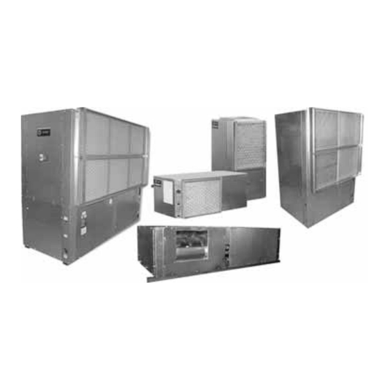
Water Source Heat Pump
Axiom™ Horizontal/Vertical
GEH/V*, EXH/V*
.5 to 25Tons, 50/60 Hz
Model Numbers
Only qualified personnel should install and service the equipment. The installation, starting up, and servicing
of heating, ventilating, and air-conditioning equipment can be hazardous and requires specific knowledge and
training. Improperly installed, adjusted or altered equipment by an unqualified person could result in death or
serious injury. When working on the equipment, observe all precautions in the literature and on the tags,
stickers, and labels that are attached to the equipment.
December 2016
GEHE 006-060 - 50/60 Hz
GEHE 072-180 - 50/60 Hz
EXHF 006-070 - 60 Hz
SAFETY WARNING
WSHP-SVX01Q-EN
GEVE 006-060 - 50/60 Hz
GEVE 072-300 - 50/60 Hz
EXVF 006-070 - 60 Hz
Advertisement
Table of Contents

Related Manuals for Trane GEHE 072-180


Summary of Contents for Trane GEHE 072-180
- Page 1 GEH/V*, EXH/V* .5 to 25Tons, 50/60 Hz Model Numbers GEHE 006-060 - 50/60 Hz GEVE 006-060 - 50/60 Hz GEHE 072-180 - 50/60 Hz GEVE 072-300 - 50/60 Hz EXHF 006-070 - 60 Hz EXVF 006-070 - 60 Hz SAFETY WARNING Only qualified personnel should install and service the equipment.
- Page 2 Practices flash, technicians MUST put on all PPE in accordance with OSHA, NFPA 70E, or other country-specific Trane believes that responsible refrigerant practices are requirements for arc flash protection, PRIOR to important to the environment, our customers, and the air servicing the unit.
-
Page 3: Copyright
Copyright This document and the information in it are the property of Trane, and may not be used or reproduced in whole or in part without written permission.Trane reserves the right to revise this publication at any time, and to make changes to its content without obligation to notify any person of such revision or change. -
Page 4: Table Of Contents
Table of Contents Copyright ......3 Air Flow Adjustment ....61 Waterside Economizer Installation . -
Page 5: Model Number Description - .5 To 25 Tons
Model Number Description - .5 to 25 Tons Digits 1-3 - Unit Configuration Digit 12 - Blower Configuration Digit 20 - Temperature Sensor GEH = Standard Efficiency Horizontal 1 = Standard Blower Motor 0 = NoTemperature Sensor .5 to 15Tons 2 = High Static Blower Motor 1 = Entering Water Sensor GEV = Standard Efficiency Vertical... -
Page 6: Model Number Description - .5 To 6 Tons
Model Number Description - .5 to 6 Tons Digits 1-3 — Unit Configuration Digit 17 — Control Types EXH =High Efficiency Horizontal D = Deluxe 24V Controls EXV =High Efficiency Vertical B = Tracer® ZN524 Controls F = UC400 — Digit 4 Development Sequence G = UC400 w/ Wireless Comm... -
Page 7: Overview Of Manual
Overview of Manual Compressor Nameplate Note: One copy of this document ships with each unit and is customer property. It must be retained by the The nameplate for the compressors are located on the unit’s maintenance personnel. compressor shell. This booklet describes proper installation, operation, and Model Number Description maintenance procedures for HVAC systems. -
Page 8: General Information
General alarm is accomplished through the lockout relay. This feature will drive dry contacts only, and cannot be Trip Recover Unit used to drive field installed control inputs.Trane provides 40 +/-4 56 +/-4 psig a 3.5-minute time delay for compressor control. - Page 9 Systems that do not contain a boiler may contain a available with 2 speed motors, selectable in the model boilerless control with electric heat.Trane® offers both a number (Digit 12, drive packages one to nine). High speed factory mounted electric heat option (.5 to 5 ton only), and airflow matches the single speed motor airflow, a field mounted duct heater option.
- Page 10 General Information Table 3. Refrigerant charge Model Heat Pump Heat Pump w/HGR (60 Hz) (oz)/(Kg) (oz)/(Kg) Circuit 1 Circuit 2 Circuit 1 Circuit 2 GEHE006 25.3 / .717 ----- 26.8 / .760 ----- GEHE009 26.0 /.737 ----- 27.5 / .780 ----- GEHE012 28.5 / .808...
- Page 11 General Information Table 3. Refrigerant charge (continued) Model Heat Pump Heat Pump w/HGR (60 Hz) (oz)/(Kg) (oz)/(Kg) EXVF006 25.7 / 0.729 ----- 27.2 / 0.771 ----- EXVF009 26.5 / 0.751 ----- 28.0 / 0.794 ----- EXVF012 29.5 / 0.836 ----- 31.5 / 0.893 ----- EXVF015...
-
Page 12: Pre-Installation
Pre-Installation unit(s) are unloaded. Once the bill of lading is signed at the jobsite, the unit(s) are now the property of the WARNING SOLDTO party and future freight claims MAY NOT be Fiberglass Wool! accepted by the freight company. Exposition to glass wool fibers without all necessary Jobsite Storage PPE equipment could result in cancer, respiratory, skin or eye irritation, which could result in death or serious... -
Page 13: Unit Dimensions
Unit Dimensions Service Clearances Per NEC requirements, 36 inches of access and working space shall be provided and maintained around all control boxes and electrical equipment to permit ready and safe operation and maintenance of such equipment. Local codes may require more clearance to electrical equipment. - Page 14 Unit Dimensions Figure 3. Clearance - GEV .5 to 5 tons & EXV .5 to 6 Tons A 24 inch clearance from other mechanical and electrical equipment (where shown) is recommended for all configurations.This will enable panel removal from the unit for service/maintenance.
- Page 15 Unit Dimensions Figure 6. Left return/left supply (GEH/EXH) F X G OPENING REFRIG BLOWER CONTROL ACCESS ACCESS PANEL HI VOLT L (W.O.) WCI mounting location LO VOLT M (W.I.) DRAIN 3/4" NPTI BACK LEFT SIDE FRONT 14" RIGHT SIDE Table 4. Dimensional data left return/left supply (GEH/EXH) GEH Unit GEH Unit...
- Page 16 Unit Dimensions Figure 7. Left return/back supply (GEH/EXH) F X G OPENING REFRIG BLOWER CONTROL ACCESS ACCESS PANEL L (W.O.) HI VOLT WCI mounting location LO VOLT M (W.I.) DRAIN BACK LEFT SIDE FRONT 3/4" NPTI 14" RIGHT SIDE Table 5. Dimensional data left return/back supply (GEH/EXH) GEH Unit GEH Unit...
- Page 17 Unit Dimensions Figure 8. Left return/right supply (GEH/EXH) REFRIG CONTROL BLOWER ACCESS ACCESS PANEL L (W.O.) HI VOLT WCI mounting location LO VOLT M (W.I.) BACK LEFT SIDE FRONT DRAIN 3/4" NPTI F X G OPENING 14" RIGHT SIDE Table 6. Dimensional data left return/right supply (GEH/EXH) GEH Unit GEH Unit...
- Page 18 Unit Dimensions Figure 9. Right return/left supply (GEH/EXH) REFRIG CONTROL BLOWER F X G ACCESS ACCESS OPENING PANEL HI VOLT WCI mounting location LO VOLT L (W.O.) BACK LEFT SIDE FRONT DRAIN M (W.I.) 3/4" NPTI 14" RIGHT SIDE Table 7. Dimensional data right return/left supply (GEH/EXH) Unit (60 Unit (50...
- Page 19 Unit Dimensions Figure 10. Right return/back supply (GEH/EXH) F X G OPENING REFRIG BLOWER ACCESS CONTROL PANEL ACCESS 14" HI VOLT WCI mounting location LO VOLT L (W.O.) DRAIN M (W.I.) BACK LEFT SIDE FRONT 3/4" NPTI RIGHT SIDE Table 8. Dimensional data right return/back supply (GEH/EXH) GEH Unit GEH Unit...
- Page 20 Unit Dimensions Figure 11. Right return/right supply (GEH/EXH) REFRIG CONTROL BLOWER ACCESS ACCESS PANEL HI VOLT WCI mounting location LO VOLT L (W.O.) F X G LEFT SIDE BACK FRONT OPENING DRAIN M (W.I.) 3/4" NPTI RIGHT SIDE Table 9. Dimensional data right return/right supply (GEH/EXH) GEH Unit GEH Unit...
- Page 21 Unit Dimensions Figure 12. Left return/top supply (GEV/EXV) BLOWER ACCESS COMP/CONTROL ACCESS W.O. WCI mounting location DRAIN HI VOLT 9 1/2” 12” 8 3/4” W.I. LO VOLT 3 5/8” 8 5/8” LEFT SIDE FRONT RIGHT SIDE Table 10. Dimensional data left return/top supply (GEV/EXV) GEV Unit GEV Unit W.I.
- Page 22 Unit Dimensions Figure 13. Left return/back supply (GEV/EXV) BLOWER ACCESS COMP/CONTROL ACCESS WCI mounting location W.O. DRAIN HI VOLT 12” 9 1/2” 8 3/4” W.I. LO VOLT 3 5/8” 3 5/8” LEFT SIDE FRONT RIGHT SIDE Table 11. Dimensional data left return/back supply (GEV/EXV) GEV Unit GEV Unit W.I.
- Page 23 Unit Dimensions Figure 14. Right return/top supply (GEV/EXV) BLOWER ACCESS COMP/CONTROL ACCESS W.O. WCI mounting location DRAIN HI VOLT 9 1/2” 12” 8 3/4” LOW VOLT W.I. 3 5/8” 3 5/8” RIGHT SIDE FRONT LEFT SIDE Table 12. Right return/top supply (GEV/EXV) GEV Unit GEV Unit W.I.
- Page 24 Unit Dimensions Figure 15. Right return/back supply (GEV/EXV) BLOWER ACCESS COMP/CONTROL ACCESS W.O. WCI mounting location DRAIN HIGH VOLT 9 1/2” 12” 8 3/4” LOW VOLT W.I. 3 5/8” 3 5/8” RIGHT SIDE LEFT SIDE FRONT Table 13. Dimensional data right return/back supply (GEV/EXV) GEV Unit GEV Unit W.I.
- Page 25 Unit Dimensions Figure 16. Right return/left supply - GEH 6 to 10 tons (60 Hz); GEH 6 to 7.5 tons (50 Hz) 79” 1 3/4” 74 1/2” 40 5/8” 36” 23 7/8” 7 5/8” TOP VIEW BLOWER ACCESS PANEL 18 3/8” 81”...
- Page 26 Unit Dimensions Figure 17. Right return/back supply - GEH 6 to 10 tons (60 Hz); GEH 6 to 7.5 tons (50 Hz) 79” 74 1/2” 1 3/4” 40 5/8” 36” 18 3/8” 23 7/8” 81” 85” BLOWER ACCESS TOP VIEW PANEL W.O.
- Page 27 Unit Dimensions Figure 18. Left return/right supply GEH 6 to 10 tons (60 Hz); GEH 6 to 7.5 tons (50 Hz) 79” 74 1/2” 1 3/4” 40 5/8” 36” 24 3/4” 7 5/8” BLOWER ACCESS TOP VIEW PANEL 18 3/8” 81”...
- Page 28 Unit Dimensions Figure 19. Left return/back supply GEH 6 to 10 tons (60 Hz); GEH 6 to 7.5 tons (50 Hz) 79” 1 3/4” 74 1/2” 40 5/8” 36” 18 3/8” 24 3/4” 81” 85” TOP VIEW BLOWER ACCESS PANEL W.O.
- Page 29 Unit Dimensions Figure 20. Right return/left supply GEH 12.5 to 15 tons (150-180) 60 Hz; GEH 10 to 12.5 tons (120-150) 50 Hz 85" 2" 74 1/2" 46 5/8" 42" 29 3/4" 7 1/8" BLOWER ACCESS TOP VIEW PANEL 21 3/8" 87"...
- Page 30 Unit Dimensions Figure 21. Right return/back supply GEH 12.5 to 15 tons (60 Hz); GEH 10 to 12.5 tons (50 Hz) 85" 74 1/2" 2" 46 5/8" 42" 21 3/8" 29 3/4" 87" 91" TOP VIEW BLOWER ACCESS PANEL W.O. 1 1/2” NPTI 61 1/4"...
- Page 31 Unit Dimensions Figure 22. Left return/right supply GEH 12.5 to 15 tons (60 Hz); GEH 10 to 12.5 tons (50 Hz) 85” 2" 74 1/2” 46 5/8” 42” 29 3/4” 7 1/8” TOP VIEW BLOWER ACCESS PANEL 21 3/8” 87” 91”...
- Page 32 Unit Dimensions Figure 23. Left return/back supply GEH 12.5 to 15 tons (60 Hz); GEH 10 to 12.5 tons (50 Hz) 85" 74 1/2" 2" 46 5/8" 42" 21 3/8" 29 3/4" 87" 91" TOP VIEW BLOWER ACCESS PANEL W.O. 1 1/2" NPTI 24 VOLT 2 1/8"...
- Page 33 Unit Dimensions Figure 24. Front return/back supply GEV 6 to 10 tons (60 Hz); 6 and 7.5 tons (50 Hz) SUPPLY OPENING 15 3/4” 1" DUCT FLANGE ACCESS PANEL FOR 13 18" SHEAVES AND BELTS 31 3/8" 36 1/4" 39 5/8" 42"...
- Page 34 Unit Dimensions Figure 25. Front return/top supply GEV 6 to 10 tons (60 Hz); 6 and 7.5 tons (50 Hz) ACCESS PANEL FOR 15 5/8 SHEAVES AND BELTS 13 1/4" 13 3/8" 31 3/8" 36 1/4" 39 5/8" 42" 38 7/8" 63"...
- Page 35 Unit Dimensions Figure 26. Back return/front supply GEV 6 to 10 tons (60 Hz); 6 and 7.5 ton (50 Hz) ACCESS PANEL FOR 39 5/8" SHEAVES AND BELTS 36 1/4" 31 3/8" 13 1/8" 15 3/4” 42" 1" 38 7/8" W.O.
- Page 36 Unit Dimensions Figure 27. Back return/top supply GEV 6 to 10 tons (60 Hz); 6 and 7.5 ton (50 Hz) ACCESS PANEL FOR 39 5/8" SHEAVES AND BELTS 36 1/4" 31 3/8" 13 1/2" 13 1/4" 15 5/8” 42" 38 7/8" W.O.
- Page 37 Unit Dimensions Figure 28. Front return/back supply GEV 12.5 to 15 tons (60 Hz); GEV 10 and 12.5 ton (50 H)z 31 1/2" 36 1/4" 10" 74 1/2" 4 3/4" 81 5/8" TOP VIEW 18 5/8" 31 1/2" 24 VOLT 15 7/8"...
- Page 38 Unit Dimensions Figure 29. Back return/front supply GEV 12.5 to 15 tons (60 Hz); GEV 10 and 12.5 ton (50 Hz) 81 5/8" 4 3/4" 74 1/2" 36 1/4" 31 1/2" 10" TOP VIEW 18 5/8" 31 1/2" 15 7/8" 38 7/8"...
- Page 39 Unit Dimensions Figure 30. Front return/top supply GEV 12.5 to 15 tons (60 Hz); GEV 10 and 12.5 ton (50 Hz) 15 7/8" 31 1/2" 36 1/4" 10" 14 3/8" 74 1/2" 4 3/4" 81 5/8" TOP VIEW 18 5/8" 31 1/2"...
- Page 40 Unit Dimensions Figure 31. Back return/top supply GEV 12.5 to 15 ton (60 Hz); GEV 10 and 12.5 ton (50 Hz) 81 5/8" 4 3/4" 74 1/2" 14 3/8" 36 1/4" 31 1/2" 15 7/8" 15 7 10" TOP VIEW 18 5/8"...
- Page 41 Unit Dimensions Figure 32. Front return/back supply GEV 20 and 25 ton (60 Hz); GEV 15 and 20 ton (50 Hz) 31 1/2" 36 1/4" 6 1/4" 74 1/2" 4 3/4" 81 5/8" TOP VIEW 19 1/8” 24 VOLT 1 1/8" O.D. 38 7/8"...
- Page 42 Unit Dimensions Figure 33. Back return/front supply GEV 20 and 25 ton (60 Hz); GEV 15 and 20 ton (50 Hz) 81 5/8" 4 3/4" 74 1/2" 36 1/4" 31 1/2" 6 1/4" TOP VIEW 38 7/8" W.O. 2" NPTI 67 5/8"...
- Page 43 Unit Dimensions Figure 34. Front return/top supply GEV 20 and 25 ton (60 Hz); GEV 15 and 20 ton (50 Hz) 31 1/2" 36 1/4" 6 1/4" 74 1/2" 4 3/4" 81 5/8" TOP VIEW 19 1/8" 38 7/8" W.O. 2" NPTI 68"...
- Page 44 Unit Dimensions Figure 35. Back return/top supply GEV 20 and 25 ton (60 Hz); GEV 15 and 20 ton (50 Hz) 81 5/8" 4 3/4" 74 1/2" 36 1/4" 31 1/2" 6 1/4" TOP VIEW 19 1/8" 38 7/8" W.O. 2" NPTI 68"...
- Page 45 Unit Dimensions Figure 36. Waterside economizer (GEH/EXH) TOP VIEW 20" A = TO FIELD SUPPLY PIPING B = TO FIELD RETURN PIPING FRONT VIEW 5" (a) Waterside economizer installation requires field piping. Table 26. Dimensional data waterside economizer (GEH/EXH) (60 Hz) (50 Hz) A NPTI B NPTI 006-015 006-012 16-1/8...
- Page 46 Unit Dimensions Figure 37. Hanging unit waterside economizer (GEH/EXH) Table 27. Dimensional data hanging unit waterside economizer (GEH/EXH) GEH Unit GEH Unit Hanging Shipping (60 Hz) (50 Hz) Weight Weight 006-015 006-012 38-3/4 18-3/4 21-3/4 54 lbs 84 lbs 018-030 015-024 44-3/4 21-3/4...
- Page 47 Unit Dimensions Figure 38. GEH 6 to 10 tons (60 Hz), GEH 6 to 7.5 tons (50 Hz) - right return with waterside economizer 9 7/8" 18 1/2" 50 5/8" 36" 23 7/8" "B" OD COPPER TO FIELD SUPPLY PIPING "A"...
- Page 48 Unit Dimensions Figure 40. GEH 12.5 to 15 tons (60 Hz), GEH 10 to 12.5 tons (50 Hz), right return with waterside economizer 9 7/8" 18 1/2" 56 1/2" 42" 29 3/4" 48 3/4" 1 5/8" OD COPPER TO FIELD SUPPLY PIPING 1 1/2"...
- Page 49 Unit Dimensions Figure 41. GEH 12.5 to 15 tons (60 Hz), GEH 10 to 12.5 tons (50 Hz), left return with waterside economizer 9 7/8" 18 1/2" 56 1/2" 42" 29 3/4" 27 1/8" 1 5/8" OD COPPER TO FIELD SUPPLY PIPING 1 1/2"...
- Page 50 Unit Dimensions Figure 42. GEV 6 to 10 tons (60 Hz), 6 and 7.5 tons (50 Hz) - waterside economizer A = TO FIELD RETURN PIPING B = TO FIELD SUPPLY PIPING 2 1/4" Table 31. Dimensional data GEV 6 to 10 tons (60 Hz), 6 and 7.5 tons (50 Hz) - waterside economizer Hanging Shipping Unit (60 Hz)
- Page 51 Unit Dimensions Figure 43. GEV 12.5 to 25 tons - waterside economizer 13" TOP VIEW A = TO FIELD RETURN PIPING B = TO FIELD SUPPLY PIPING 2 3/4" SIDE VIEW FRONT VIEW Table 32. Dimensional data GEV 12.5 to 25 tons - waterside economizer GEV (60 Hz) GEV (50 Hz) NPTI...
- Page 52 Unit Dimensions Figure 44. Waterside economizer coil piping diagram Note: (applicable only to 6 to 25 ton models) Unit WSE Coil WSE Coil Unit Water Outlet Inlet Water Outlet Inlet Unit Heat Coil Exchanger Port A Port AB 3 Way Valve Please match the entering water port marking with...
-
Page 53: Weights
Weights Table 36. Unit weights EXH .5 to 6 tons (continued) Table 33. Unit weights GEH .5 to 5 tons Shipping Weight with Unit Weight without Shipping Weight with Unit Weight without EXH (60 Hz) pallet (lbs) pallet (lbs) GEH (60 Hz) pallet (lbs) pallet (lbs) Weight Distribution for Hanging the GEH... -
Page 54: Installation
Installation Main Electrical WARNING Proper Field Wiring and Grounding WARNING Required! Hazardous Voltage! Failure to follow code could result in death or serious Failure to disconnect power before servicing could injury. All field wiring MUST be performed by qualified result in death or serious injury. Disconnect all electric personnel. -
Page 55: Supply-Air Ductwork
Installation Supply-Air Ductwork Figure 48. Flexible return-air connector (field provided) GEV return duct Horizontal .5 to 5 ton and EXHF units require duct flanges to be field installed.The duct flange ships in a box on the side of the unit. Install the flange with (8) 3/8 in. factory supplied screws. -
Page 56: Ducted Filter Rack
Installation Table 39. Ducted filter opening size Figure 50. Install return-air duct panel Unit Size A (in.) B (in.) C (in.) Install the return- Unit Top GEV 048-060 30.7 26.6 air duct panel to EXH 006-015 21.1 15.4 the return-air opening with the EXH 018-030 24.5... -
Page 57: Sound Attenuation Pad
Installation unit. All plumbing to the unit should conform per Figure 52. Install top/bottom filter rack national and local codes and is the responsibility of the contractor. Figure 54. Hanging the unit RETURN-AIR SUPPLY-AIR 3. Install the 1”or 2” filter. Figure 53. -
Page 58: Supply/Return Pipe Connections
Installation Supply/Return Pipe Connections Field Installed Power Wiring Figure 56. Supply/return pipe connections WARNING Proper Field Wiring and Grounding Required! Failure to follow code could result in death or serious injury. All field wiring MUST be performed by qualified personnel. Improperly installed and grounded field RETURN wiring poses FIRE and ELECTROCUTION hazards. -
Page 59: Control Power Transformer
Installation Control Power Transformer NOTICE The 24 V control power transformers are to be used only Component Failure! with the accessories called out in this manual. A 50 VA transformer is externally fused.Transformers rated Resistance in excess of 3 Ohms per conductor could greater than 50 VA are equipped with circuit breakers. -
Page 60: Blower Motor Speed-Tap Retrofit
Installation Figure 60. Low-voltage connection (GEH/V 6 to 25 ton) WARNING Deluxe Controls with Deluxe Controls with Proper Field Wiring and Grounding -all Heat Pump Units w/ Reheat -all Heat Pump Units w/ Reheat using X13511090010 (T8511) using X13511091010/X13511092010 (T7300) Required! 1TB2 1TB2... -
Page 61: Hole Plug Installation
Installation Hole Plug Installation Figure 63. Wiring change Figure 65. Hole plug installation Connecting Desired Speed-tap Wire 1. Locate two Hayco plastic plugs enclosed with the Installation, Operation, and Maintenance manual. 5. For units without hot gas reheat, select desired speed- tap wire. -
Page 62: Waterside Economizer Installation
Installation disconnected when the DIP switch is set, the motor will not Figure 66. Fan motor and sheave adjustment be programmed to the new setting. 1.Belt Profile A = 110% of rated airflow 2.Adjustment Bolt and Profile B = 100% of rated airflow Plate Profile C = 90% of rated airflow 3.Sheave... - Page 63 10-factory provided screws.The economizing package fits to the outside of the of the water-source heat pump.Trane recommends the mating of the systems be made via 3- screws spaced evenly across the top, 3-screws spaced evenly across the bottom (installed immediately after hanging the unit), and 2-screws on each side.
- Page 64 Installation 9. Wire-tie the sensor to the water SUPPLY side of the WHT = 1TB1-15 piping (ON, or BEFORE) the 2-position valve. See Figure 77, p. Figure 74, p. Figure 77. Step 12 Figure 74. Step 9 13. Bundle excess valve wire, and wire tie the bundle neatly.
-
Page 65: Waterside Economizer Installation For Geh And Gev 6 To 25 Ton Models
Insulating the piping will stop condensation from forming on the pipe and dripping onto the ceiling tiles. WARNING Note: Trane does not provide insulation on the Hazardous Voltage! economizing piping package.This insulation must Failure to disconnect power before servicing could be field provided and field installed. - Page 66 Insulating the piping will help stop condensation from forming on the pipe. Notes: • Trane does not provide insulation on the economizing piping package.This insulation must be field provided and field installed. • Trane does not provide condensate overflow protection of the waterside economizer.This must be...
-
Page 67: Waterside Economizer Start-Up Sequence
Waterside Economizer Start-Up Sequence 1. Set the thermostat to the highest position. 6. Leave unit off for approximately FIVE minutes to allow for pressure equalization. 2. Set the thermostat system switch to COOL with the fan control to AUTO.The compressor should NOT run. 7. - Page 68 Waterside Economizer Start-Up Sequence Table 46. Waterside economizing three-way valve specifications Valve Conn. Valve Pres. "Valve Close- Valve Temp. Unit Size (60 Hz) Unit Size (50 Hz) Size Rating off pressure Range Actuator Non-spring return type "0ºF to 212ºF 24 VAC +/- 20% GEH006-015 GEH006-012 1/2 FPT...
-
Page 69: Electrical Data
Electrical Data Table 47. Electrical data standard static motors (.5 to 25 tons), single speed blower motor (6 to 25 tons) Maximum Total Comp Comp Blower Blower Minimum Overcurrent Electric Electric Unit No. of Motor Motor Circuit Protective Heat Heat Model Volts (ea) - Page 70 Electrical Data Table 47. Electrical data standard static motors (.5 to 25 tons), single speed blower motor (6 to 25 tons) (continued) Maximum Total Comp Comp Blower Blower Minimum Overcurrent Electric Electric Unit No. of Motor Motor Circuit Protective Heat Heat Model Volts...
- Page 71 Electrical Data Table 47. Electrical data standard static motors (.5 to 25 tons), single speed blower motor (6 to 25 tons) (continued) Maximum Total Comp Comp Blower Blower Minimum Overcurrent Electric Electric Unit No. of Motor Motor Circuit Protective Heat Heat Model Volts...
- Page 72 Electrical Data Table 47. Electrical data standard static motors (.5 to 25 tons), single speed blower motor (6 to 25 tons) (continued) Maximum Total Comp Comp Blower Blower Minimum Overcurrent Electric Electric Unit No. of Motor Motor Circuit Protective Heat Heat Model Volts...
- Page 73 Electrical Data Table 47. Electrical data standard static motors (.5 to 25 tons), single speed blower motor (6 to 25 tons) (continued) Maximum Total Comp Comp Blower Blower Minimum Overcurrent Electric Electric Unit No. of Motor Motor Circuit Protective Heat Heat Model Volts...
- Page 74 Electrical Data Table 47. Electrical data standard static motors (.5 to 25 tons), single speed blower motor (6 to 25 tons) (continued) Maximum Total Comp Comp Blower Blower Minimum Overcurrent Electric Electric Unit No. of Motor Motor Circuit Protective Heat Heat Model Volts...
- Page 75 Electrical Data Table 47. Electrical data standard static motors (.5 to 25 tons), single speed blower motor (6 to 25 tons) (continued) Maximum Total Comp Comp Blower Blower Minimum Overcurrent Electric Electric Unit No. of Motor Motor Circuit Protective Heat Heat Model Volts...
- Page 76 Electrical Data Table 48. Electrical data high static motors .5 to 5 tons (continued) Maximum Total Comp Comp Blower Blower Minimum Overcurrent Electric Electric Model Unit No. of Motor Motor Motor Circuit Protective Heat Heat Volts (ea) (ea) Comp. Ampacity Device Amps GEH/V006...
- Page 77 Electrical Data Table 48. Electrical data high static motors .5 to 5 tons (continued) Maximum Total Comp Comp Blower Blower Minimum Overcurrent Electric Electric Model Unit No. of Motor Motor Motor Circuit Protective Heat Heat Volts (ea) (ea) Comp. Ampacity Device Amps GEH/V030...
- Page 78 Electrical Data Table 48. Electrical data high static motors .5 to 5 tons (continued) Maximum Total Comp Comp Blower Blower Minimum Overcurrent Electric Electric Model Unit No. of Motor Motor Motor Circuit Protective Heat Heat Volts (ea) (ea) Comp. Ampacity Device Amps GEH/V048...
- Page 79 Electrical Data Table 49. Electrical data - ECM motors - .5 to 6 tons EXH*/EXV* (continued) Maximum Total Comp Comp Blower Blower Minimum Overcurrent Model Unit Motor Motor Circuit Protective Electric Electric Volts (ea) (ea) Ampacity Device Heat kW Heat Amps EXH015 230/60/1 11.76...
- Page 80 Electrical Data Table 49. Electrical data - ECM motors - .5 to 6 tons EXH*/EXV* (continued) Maximum Total Comp Comp Blower Blower Minimum Overcurrent Model Unit Motor Motor Circuit Protective Electric Electric Volts (ea) (ea) Ampacity Device Heat kW Heat Amps EXH048 230/60/1 39.88...
- Page 81 Electrical Data Table 49. Electrical data - ECM motors - .5 to 6 tons EXH*/EXV* (continued) Maximum Total Comp Comp Blower Blower Minimum Overcurrent Model Unit Motor Motor Circuit Protective Electric Electric Volts (ea) (ea) Ampacity Device Heat kW Heat Amps EXV015 208/60/1 10.45...
- Page 82 Electrical Data Table 49. Electrical data - ECM motors - .5 to 6 tons EXH*/EXV* (continued) Maximum Total Comp Comp Blower Blower Minimum Overcurrent Model Unit Motor Motor Circuit Protective Electric Electric Volts (ea) (ea) Ampacity Device Heat kW Heat Amps EXV048 208/60/1 36.35...
- Page 83 Electrical Data Table 50. Electrical data two speed blower motor 6 to 25 tons (continued) Maximum Comp Blower Blower Minimum Overcurrent Model Total Comp RLA No. of Motor Motor Motor Circuit Protective Volts (ea) (ea) Comp. Cmp MCC Ampacity Device GEH090 460/60/3 13.6...
- Page 84 Electrical Data Table 50. Electrical data two speed blower motor 6 to 25 tons (continued) Maximum Comp Blower Blower Minimum Overcurrent Model Total Comp RLA No. of Motor Motor Motor Circuit Protective Volts (ea) (ea) Comp. Cmp MCC Ampacity Device GEV072 208/60/3 24.1...
- Page 85 Electrical Data Table 50. Electrical data two speed blower motor 6 to 25 tons (continued) Maximum Comp Blower Blower Minimum Overcurrent Model Total Comp RLA No. of Motor Motor Motor Circuit Protective Volts (ea) (ea) Comp. Cmp MCC Ampacity Device GEV180 230/60/3 63.2...
-
Page 86: Pre-Start Checklist
Pre-Start Checklist Before energizing the unit, the following system devices • Are the low/high-side pressure temperature caps must be checked: secure and in place? • Is the high voltage power supply correct and in • Are all the unit access panels secure and in place? accordance with the nameplate ratings? •... -
Page 87: Start-Up
Start-Up Initial Unit Start-up Table 52. Checklist MODE Heat Cool Note: Start-up with the heat pump thermostat is included _________PSI _________PSI Pressure Differential below: 1. Set the thermostat to the highest position. COMPRESSOR 2. Set the thermostat system switch to COOL with the fan Amps control to AUTO.The compressor should NOT run. - Page 88 Start-Up Table 53. Operating pressures in cooling/heating for GE* units Operating Data Cooling Heating Entering Water Water Water Water Suction Discharge Temp Air Temp Suction Discharge Temp Temp Temp Flow Pressure Pressure Rise Drop Pressure Pressure Drop Rise Model No. (°F) (GPM) (psig)
- Page 89 Start-Up Table 53. Operating pressures in cooling/heating for GE* units (continued) Operating Data Cooling Heating Entering Water Water Water Water Suction Discharge Temp Air Temp Suction Discharge Temp Temp Temp Flow Pressure Pressure Rise Drop Pressure Pressure Drop Rise Model No. (°F) (GPM) (psig)
- Page 90 Start-Up Table 53. Operating pressures in cooling/heating for GE* units (continued) Operating Data Cooling Heating Entering Water Water Water Water Suction Discharge Temp Air Temp Suction Discharge Temp Temp Temp Flow Pressure Pressure Rise Drop Pressure Pressure Drop Rise Model No. (°F) (GPM) (psig)
- Page 91 Start-Up Table 53. Operating pressures in cooling/heating for GE* units (continued) Operating Data Cooling Heating Entering Water Water Water Water Suction Discharge Temp Air Temp Suction Discharge Temp Temp Temp Flow Pressure Pressure Rise Drop Pressure Pressure Drop Rise Model No. (°F) (GPM) (psig)
- Page 92 Start-Up Table 53. Operating pressures in cooling/heating for GE* units (continued) Operating Data Cooling Heating Entering Water Water Water Water Suction Discharge Temp Air Temp Suction Discharge Temp Temp Temp Flow Pressure Pressure Rise Drop Pressure Pressure Drop Rise Model No. (°F) (GPM) (psig)
- Page 93 Start-Up Table 53. Operating pressures in cooling/heating for GE* units (continued) Operating Data Cooling Heating Entering Water Water Water Water Suction Discharge Temp Air Temp Suction Discharge Temp Temp Temp Flow Pressure Pressure Rise Drop Pressure Pressure Drop Rise Model No. (°F) (GPM) (psig)
- Page 94 Start-Up Table 53. Operating pressures in cooling/heating for GE* units (continued) Operating Data Cooling Heating Entering Water Water Water Water Suction Discharge Temp Air Temp Suction Discharge Temp Temp Temp Flow Pressure Pressure Rise Drop Pressure Pressure Drop Rise Model No. (°F) (GPM) (psig)
- Page 95 Start-Up Table 53. Operating pressures in cooling/heating for GE* units (continued) Operating Data Cooling Heating Entering Water Water Water Water Suction Discharge Temp Air Temp Suction Discharge Temp Temp Temp Flow Pressure Pressure Rise Drop Pressure Pressure Drop Rise Model No. (°F) (GPM) (psig)
- Page 96 Start-Up Table 53. Operating pressures in cooling/heating for GE* units (continued) Operating Data Cooling Heating Entering Water Water Water Water Suction Discharge Temp Air Temp Suction Discharge Temp Temp Temp Flow Pressure Pressure Rise Drop Pressure Pressure Drop Rise Model No. (°F) (GPM) (psig)
- Page 97 Start-Up Table 53. Operating pressures in cooling/heating for GE* units (continued) Operating Data Cooling Heating Entering Water Water Water Water Suction Discharge Temp Air Temp Suction Discharge Temp Temp Temp Flow Pressure Pressure Rise Drop Pressure Pressure Drop Rise Model No. (°F) (GPM) (psig)
- Page 98 Start-Up Table 53. Operating pressures in cooling/heating for GE* units (continued) Operating Data Cooling Heating Entering Water Water Water Water Suction Discharge Temp Air Temp Suction Discharge Temp Temp Temp Flow Pressure Pressure Rise Drop Pressure Pressure Drop Rise Model No. (°F) (GPM) (psig)
- Page 99 Start-Up Table 53. Operating pressures in cooling/heating for GE* units (continued) Operating Data Cooling Heating Entering Water Water Water Water Suction Discharge Temp Air Temp Suction Discharge Temp Temp Temp Flow Pressure Pressure Rise Drop Pressure Pressure Drop Rise Model No. (°F) (GPM) (psig)
- Page 100 Start-Up Table 53. Operating pressures in cooling/heating for GE* units (continued) Operating Data Cooling Heating Entering Water Water Water Water Suction Discharge Temp Air Temp Suction Discharge Temp Temp Temp Flow Pressure Pressure Rise Drop Pressure Pressure Drop Rise Model No. (°F) (GPM) (psig)
- Page 101 Start-Up Table 54. Operating pressures in cooling/heating for EX* units (60 Hz) (continued) Operating Data Cooling Heating Entering Water Suction Discharge Water Air temp Suction Discharge Water Air temp water flow pressure pressure temp rise drop pressure pressure Temp drop rise Model temp (ºF)
- Page 102 Start-Up Table 54. Operating pressures in cooling/heating for EX* units (60 Hz) (continued) Operating Data Cooling Heating Entering Water Suction Discharge Water Air temp Suction Discharge Water Air temp water flow pressure pressure temp rise drop pressure pressure Temp drop rise Model temp (ºF)
- Page 103 Start-Up Table 54. Operating pressures in cooling/heating for EX* units (60 Hz) (continued) Operating Data Cooling Heating Entering Water Suction Discharge Water Air temp Suction Discharge Water Air temp water flow pressure pressure temp rise drop pressure pressure Temp drop rise Model temp (ºF)
- Page 104 Start-Up Table 54. Operating pressures in cooling/heating for EX* units (60 Hz) (continued) Operating Data Cooling Heating Entering Water Suction Discharge Water Air temp Suction Discharge Water Air temp water flow pressure pressure temp rise drop pressure pressure Temp drop rise Model temp (ºF)
- Page 105 Start-Up Table 54. Operating pressures in cooling/heating for EX* units (60 Hz) (continued) Operating Data Cooling Heating Entering Water Suction Discharge Water Air temp Suction Discharge Water Air temp water flow pressure pressure temp rise drop pressure pressure Temp drop rise Model temp (ºF)
- Page 106 Start-Up Table 54. Operating pressures in cooling/heating for EX* units (60 Hz) (continued) Operating Data Cooling Heating Entering Water Suction Discharge Water Air temp Suction Discharge Water Air temp water flow pressure pressure temp rise drop pressure pressure Temp drop rise Model temp (ºF)
- Page 107 Start-Up Table 54. Operating pressures in cooling/heating for EX* units (60 Hz) (continued) Operating Data Cooling Heating Entering Water Suction Discharge Water Air temp Suction Discharge Water Air temp water flow pressure pressure temp rise drop pressure pressure Temp drop rise Model temp (ºF)
-
Page 108: Water Pressure Drop
Start-Up Table 54. Operating pressures in cooling/heating for EX* units (60 Hz) (continued) Operating Data Cooling Heating Entering Water Suction Discharge Water Air temp Suction Discharge Water Air temp water flow pressure pressure temp rise drop pressure pressure Temp drop rise Model temp (ºF) - Page 109 Start-Up Table 55. Cooling water pressure drops (WPD) in feet of Table 57. Heating water pressure drops (WPD) in feet of head for GE* units - .5- 6 ton (continued) head for GE* units Unit Size Unit Size Unit Size Unit Size (60 Hz) (50 Hz)
-
Page 110: Water Volume
Start-Up Table 59. Water volume for GE* units (continued) Table 58. Heating water pressure drops (WPD) in feet of head for EX* units Water Side Water Side Water Side Unit Size Unit Size Volume Volume Volume Unit Size Unit Size (60 Hz) (50 Hz) (gallons) -
Page 111: Maintenance
Maintenance Table 61. Filter sizing (continued) WARNING Size (60 Hz) Size (50 Hz) Filter Size (Nominal) inches Hazardous Service Procedures! 20 x 20 20 x 25 Failure to follow all precautions in this manual and on 20 x 25 the tags, stickers, and labels could result in death or serious injury. -
Page 112: Condensate Trap
Maintenance scale.This service should be performed by an experienced service person. WARNING Hazardous Chemicals! Failure to follow all safety instructions below could result in death or serious injury. Coil cleaning agents can be either acidic or highly alkaline and can burn severely if contact with skin occurs. -
Page 113: Troubleshooting
Troubleshooting Deluxe Controls WARNING Troubleshooting units which contain the deluxe control Hazardous Service Procedures! option may be made easy by using the three LEDs (light emitting diodes).These LEDs are provided for indicating Failure to follow all precautions in this manual and on the operating mode of the controller.The LEDs are the tags, stickers, and labels could result in death or intended to aid in troubleshooting.The LEDs are labeled... - Page 114 Troubleshooting Table 64. Troubleshooting table (continued) Problem Heating Cooling Cause Correction Dirty filter Replace/clean Blower RPM too low Correct Loss of conditioned air due to leaks in Repair leaks ductwork Introduction of excessively hot return-air Correct Introduction of excessively cold return-air Correct Locate leak, repair and recharge by Low on refrigerant charge...
-
Page 115: Wiring Diagrams
Wiring Diagrams This section contains wiring diagrams (Figure 82, p. 116– Table 65. Isolation valve wiring Figure 89, p. 123) and isolation valve wiring connections (Table 65, p. 115). 3-wire Honeywell isolation valve connections Control type Blue Brown Black Basic 24V 1TB1-6 1TB1-1 1TB1-4... - Page 116 Wiring Diagrams Figure 82. GEH_V (.5 to 5 tons) - basic-208V - 60 Hz - 1 ph (a) Wiring diagrams provided in the catalog are generic. A unit specific As Built wiring diagram is located on the unit control panel. WSHP-SVX01Q-EN...
- Page 117 Wiring Diagrams Figure 83. GEH_V (.5 to 1.5 tons) - basic-208V - 60 Hz - 3 ph (a) Wiring diagrams provided in the catalog are generic. A unit specific As Built wiring diagram is located on the unit control panel. WSHP-SVX01Q-EN...
- Page 118 Wiring Diagrams Figure 84. GEH_V (.5 to 5 tons) - basic 24V - 460V-60 Hz - 3 ph (a) Wiring diagrams provided in the catalog are generic. A unit specific As Built wiring diagram is located on the unit control panel. WSHP-SVX01Q-EN...
- Page 119 Wiring Diagrams Figure 85. GEH_V (6-25 tons) - deluxe-380-420V - 50 Hz - 3 ph ISOLATED GENERAL ALARM CONTACTS. CONTACTS CLOSE WHEN CONTROL 1U1 AND 1U2 GOES INTO MANUAL LOCKOUT MODE. CONTACTS RATED FOR CLASS 2 24V. TERMINAL 1TB2-9 AND 10. VERIFY TEST JUMPER HAS BEEN REMOVED TO PREVENT CONTROL TIMING ERRORS.
- Page 120 Wiring Diagrams Figure 86. GEH_V (6-25 tons) - deluxe 24V - 460V-60 Hz - 3 ph (a) Wiring diagrams provided in the catalog are generic. A unit specific As Built wiring diagram is located on the unit control panel. WSHP-SVX01Q-EN...
- Page 121 Wiring Diagrams Figure 87. EXH/EXV - deluxe 24V - 460V-60 Hz - 3 ph - (ECM motor wiring diagram) (a) Wiring diagrams provided in the catalog are generic. A unit specific As Built wiring diagram is located on the unit control panel. WSHP-SVX01Q-EN...
- Page 122 Wiring Diagrams Figure 88. GEH_V (6 to 25 tons) - Tracer® ZN524-460V - 60 Hz - 3 ph (a) Wiring diagrams provided in the catalog are generic. A unit specific As Built wiring diagram is located on the unit control panel. WSHP-SVX01Q-EN...
- Page 123 Wiring Diagrams Figure 89. EXH_V - Tracer® ZN524 460V-60 Hz - 3 ph - (ECM motor wiring diagram) (a) Wiring diagrams provided in the catalog are generic. A unit specific As Built wiring diagram is located on the unit control panel. WSHP-SVX01Q-EN...
- Page 124 Wiring Diagrams Figure 90. GEH_V (.5 to 1.5) tons - UC400 (a) Wiring diagrams provided in the catalog are generic. A unit specific As Built wiring diagram is located on the unit control panel. WSHP-SVX01Q-EN...
- Page 125 Wiring Diagrams Figure 91. GEH_V (2 to 5) tons - UC400 (a) Wiring diagrams provided in the catalog are generic. A unit specific As Built wiring diagram is located on the unit control panel. WSHP-SVX01Q-EN...
- Page 126 Wiring Diagrams Figure 92. GEH_V (6 to 25 tons) - UC400 (a) Wiring diagrams provided in the catalog are generic. A unit specific As Built wiring diagram is located on the unit control panel. WSHP-SVX01Q-EN...
-
Page 127: Warranty Information
Warranty Information Standard Warranty Extended Warranty The standard water-source heat pump warranty isTrane’s The optional extended warranty is a second through fifth parts-only warranty, running 12 months from startup, not year warranty.The time starts at the end of the standard 1 to exceed 18-months from shipment. - Page 128 Ingersoll Rand (NYSE:IR) advances the quality of life by creating comfortable, sustainable and efficient environments. Our people and our family of brands—including Club Car®, Ingersoll Rand®,Thermo King® andTrane®—work together to enhance the quality and comfort of air in homes and buildings; transport and protect food and perishables; and increase industrial productivity and efficiency.
Need help?
Do you have a question about the GEHE 072-180 and is the answer not in the manual?
Questions and answers