Table of Contents
Advertisement
Installation, Operation, and Maintenance
Water Source Heat Pump
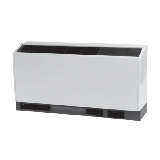
Axiom™ High Efficiency Console
0.5 to 1.5 Tons — 50/60 Hz
Model Numbers:
GECE 006, 009, 012, 015, 018 (60 Hz)
GECE 006, 009, 012, 015 (50 Hz)
Only qualified personnel should install and service the equipment. The installation, starting up, and servicing of
heating, ventilating, and air-conditioning equipment can be hazardous and requires specific knowledge and training.
Improperly installed, adjusted or altered equipment by an unqualified person could result in death or serious injury.
When working on the equipment, observe all precautions in the literature and on the tags, stickers, and labels that are
attached to the equipment.
March 2021
SAFETY WARNING
WSHP-SVX11E-EN
Advertisement
Table of Contents

Related Manuals for Trane Axiom GECE 006


Summary of Contents for Trane Axiom GECE 006
- Page 1 Installation, Operation, and Maintenance Water Source Heat Pump Axiom™ High Efficiency Console 0.5 to 1.5 Tons — 50/60 Hz Model Numbers: GECE 006, 009, 012, 015, 018 (60 Hz) GECE 006, 009, 012, 015 (50 Hz) SAFETY WARNING Only qualified personnel should install and service the equipment. The installation, starting up, and servicing of heating, ventilating, and air-conditioning equipment can be hazardous and requires specific knowledge and training.
- Page 2 (Global Harmonized System of Classification and compounds have the same potential impact to the Labeling of Chemicals) guidelines for information on environment. Trane advocates the responsible handling of allowable personal exposure levels, proper all refrigerants-including industry replacements for CFCs respiratory protection and handling instructions.
- Page 3 Copyright This document and the information in it are the property of Trane, and may not be used or reproduced in whole or in part without written permission. Trane reserves the right to revise this publication at any time, and to make changes to its content without obligation to notify any person of such revision or change.
-
Page 4: Table Of Contents
Table of Contents Model Number Description ....5 General Information ..... 6 Jobsite Inspection . -
Page 5: Model Number Description
Model Number Description Digits 1-3 — Unit Configuration Digit 18 — Tstat/Sensor Location Digit 27 — Paint Color 0 = No Paint Selection Available GEC = High Efficiency Console 0 = Wall Mounted Location 1 = Unit Mounted Location with Standard 1 = Deluxe Beige Digit 4 —... -
Page 6: General Information
General Information Jobsite Inspection Jobsite Storage Each unit has been inspected, tested and operated at the NOTICE: factory by production and quality associates prior to being Microbial Growth! crated for safe transit. However, rough handling or accidents can occur resulting in damaged equipment Wet interior unit insulation can become an being delivered. -
Page 7: Unit Dimensions
Unit Dimensions Service Clearances clearance from other mechanical and electrical equipment on three service sides (shown below). This enables panel removal from the unit for service/maintenance ability. Access to the unit for servicing purposes should be provided at installation. All configurations require Figure 2. - Page 8 Unit Dimensions Figure 4. GEC 0.5 to 1.5 tons (60 Hz), 0.5 to 1.25 tons (50 Hz) - cabinet (LH) piping connection SUPPLY AIR GRILLE 48" 12" BACK UNIT PIPE & ELEC. FIELD HOOK-UP 4" 9 5/8" TOP VIEW 3/4" 3/4"...
- Page 9 Unit Dimensions Figure 5. GEC 0.5 to 1.5 tons (60 Hz), 0.5 to 1.25 tons (50 Hz) - subbase (RH) 48" 3/4" 4 3/4" TOP VIEW 9 1/4" 15" 33" ISO VIEW 6" WSHP-SVX11E-EN...
- Page 10 Unit Dimensions Figure 6. GEC 0.5 to 1.5 tons (60 Hz), 0.5 to 1.25 tons (50 Hz) - subbase (LH) 48" 3/4" 4 3/4" TOP VIEW 15" 6" 13 1/4" 33" ISO VIEW WSHP-SVX11E-EN...
- Page 11 Unit Dimensions Figure 7. GEC 0.5 to 1.5 tons (60 Hz), 0.5 to 1.25 tons (50 Hz) - cabinet (RH) piping extended length 63" BACK OF UNIT 12" PIPE & ELEC. FIELD HOOK-UP. SUPPLY AIR GRILLE 1" 18 7/8" 9 1/4" TOP VIEW 1"...
- Page 12 Unit Dimensions Figure 8. GEC 0.5 to 1.5 tons (60 Hz), 0.5 to 1.25 tons (50 Hz) - cabinet (LH) piping extended length 63" SUPPLY AIR GRILLE BACK OF UNIT 12" PIPE & ELEC. FIELD HOOK-UP 8 3/4" TOP VIEW 9 1/4"...
- Page 13 Unit Dimensions Figure 9. GEC 0.5 to 1.5 tons (60 Hz), 0.5 to 1.25 tons (50 Hz) - subbase (RH) extended length 63" 3/4" 19 3/4" TOP VIEW 9 1/4" 15" 33" ISO VIEW 6" WSHP-SVX11E-EN...
- Page 14 Unit Dimensions Figure 10. GEC 0.5 to 1.5 tons (60 Hz), 0.5 to 1.25 tons (50 Hz) - subbase (LH) extended length 63" 3/4" 19 3/4" TOP VIEW 15" 6" 28" 33" ISO VIEW WSHP-SVX11E-EN...
- Page 15 Unit Dimensions Figure 11. GEC 0.5 to 1.5 tons (60 Hz), 0.5 to 1.25 tons (50 Hz) - cabinet (RH) low height unit 48" 12" BACK OF UNIT FIELD ADJUSTABLE BI-DIRECTIONAL GRILLES PIPE & ELECTRICAL 3/4" FIELD HOOK-UP 4" 9 5/8" TOP VIEW 3/4"...
- Page 16 Unit Dimensions Figure 12. GEC 0.5 to 1.5 tons (60 Hz), 0.5 to 1.25 tons (50 Hz) - cabinet (LH) low height unit FIELD ADJUSTABLE BI-DIRECTIONAL GRILLES 48" 12" BACK OF UNIT PIPE & ELEC. FIELD HOOK-UP 4" 9 5/8" TOP VIEW 3/4"...
- Page 17 Unit Dimensions Figure 13. GEC 0.5 to 1.5 tons (60 Hz), 0.5 to 1.25 tons (50 Hz) - chassis (RH) 2 3/8" 42 1/4" 6 3/8" 11 1/2" 4 1/4" CONTROL BOX TOP VIEW SERVICE PANEL WATER OUT 2 1/8" .625 ODS 3/4"...
- Page 18 Unit Dimensions Figure 14. GEC 0.5 to 1.5 tons (60 Hz), 0.5 to 1.25 tons (50 Hz) - chassis (LH) 42 1/4" 6 3/8" 11 1/2" 4 1/4" CONTROL BOX SERVICE PANEL HIGH VOLTAGE BOX TOP VIEW 2 1/8" 1 3/8" WATER OUT .625 ODS.
-
Page 19: Weights
Weights Table 1. Unit weights GEC (0.5 to 1.5 tons) Unit Size Shipping Weight with Pallet Shipping Weight without Pallet Unit Weight (lbs) Chassis Weight (lbs) Unit Weight (lbs) Chassis Weight (lbs) WSHP-SVX11E-EN... -
Page 20: Installation
Installation alignment, re-install screws 2 and 3 in the final installation of the unit (Step 11). WARNING Hazardous Voltage! Failure to disconnect power before servicing could result in death or serious injury. Disconnect all electric power, including remote disconnects before servicing. Follow proper lockout/tagout procedures to ensure the power can not be inadvertently energized. - Page 21 For units that contain left hand out pipe. Trane recommends a ½ in. x ¾ in. nominal ell piping, a low voltage crossover to the 18-pole terminal to be field brazed to the factory ½...
- Page 22 Installation 19. For units with the factory provided receptacle box options, the receptacle plug may now be connected to the electrical outlet. WSHP-SVX11E-EN...
-
Page 23: Electrical Data
Electrical Data Table 2. Electrical data (0.5 to 1.5 tons) Maximum Total Comp Comp Blower Blower Minimum Overcurrent Electric Electric Unit No. of Motor Motor Circuit Protective Heat Heat Model Volts (ea) (ea) Comp Motors Ampacity Device Amps GEC006 115/60/1 30.0 0.90 1/30... - Page 24 Electrical Data Table 2. Electrical data (0.5 to 1.5 tons) (continued) Maximum Total Comp Comp Blower Blower Minimum Overcurrent Electric Electric Unit No. of Motor Motor Circuit Protective Heat Heat Model Volts (ea) (ea) Comp Motors Ampacity Device Amps GEC015 220-240/50/1 28.0 11.1 0.70...
-
Page 25: Pre-Start Checklist
Pre-Start Checklist Before energizing the unit, the following system devices must be checked: • Is the high voltage power supply correct and in accordance with the nameplate ratings? • Is the field wiring and circuit protection the correct size? • Is the low voltage control circuit wiring correct per the unit wiring diagram? •... -
Page 26: Start-Up
Start-Up Initial Unit Start-up MODE Heat Cool Entering fluid temperature Note: Start-up for the Tracer® ZN524 controller may be Leaving fluid temperature found in CNT-SVX11*-EN. Start-up for wall- Temperature differential mounted thermostats found in thermostat Return-air temperature DB/WB manufacturer literature. Supply-air temperature DB/WB Start-up with the conventional thermostat is included Temperature differential... - Page 27 Start-Up Table 4. Operating pressures in cooling/heating for GEC* units Operating Data Cooling Heating Entering Water Water Water Water Suction Discharge Temp Air Temp Suction Discharge Temp Air Temp Temp Flow Pressure, Pressure, Rise Drop Pressure Pressure Drop Rise Model GEC* (°F) (GPM) (psig)
- Page 28 Start-Up Table 4. Operating pressures in cooling/heating for GEC* units (continued) Operating Data Cooling Heating Entering Water Water Water Water Suction Discharge Temp Air Temp Suction Discharge Temp Air Temp Temp Flow Pressure, Pressure, Rise Drop Pressure Pressure Drop Rise Model GEC* (°F) (GPM)
-
Page 29: Water Pressure Drop
Start-Up Table 4. Operating pressures in cooling/heating for GEC* units (continued) Operating Data Cooling Heating Entering Water Water Water Water Suction Discharge Temp Air Temp Suction Discharge Temp Air Temp Temp Flow Pressure, Pressure, Rise Drop Pressure Pressure Drop Rise Model GEC* (°F) (GPM) -
Page 30: Water Volume
Start-Up Water Volume Table 7 is provided for use in calculating glycol requirements for the unit. Table 7. Water volume for GEC* units Water Side Water Side Water Side Unit Size Unit Size Volume Volume Volume (60 Hz) (50 Hz) (gallons) 006-009 13.6... -
Page 31: Maintenance
Maintenance Table 9. Water quality WARNING Scaling Amount Hazardous Service Procedures! Calcium and magnesium (total hardness) Less than 350 ppm Failure to follow all precautions in this manual and on Corrosion the tags, stickers, and labels could result in death or serious injury.... -
Page 32: Troubleshooting
Troubleshooting Deluxe 24V Controls WARNING Troubleshooting units which contain the deluxe 24V Hazardous Service Procedures! control option may be made easy by using the three LEDs Failure to follow all precautions in this manual and on (light emitting diodes). These LEDs are provided for the tags, stickers, and labels could result in death or indicating the operating mode of the controller. - Page 33 Troubleshooting Table 11. Troubleshooting table (continued) Problem Heating Cooling Cause Correction Dirty filter Replace/clean Blower RPM too low Correct Loss of conditioned air due to leaks in Repair leaks ductwork Introduction of excessively hot return-air Correct Introduction of excessively cold return-air Correct Locate leak, repair and recharge by Low on refrigerant charge...
-
Page 34: Wiring Diagrams
Wiring Diagrams Figure 15. Deluxe 24V controls WSHP-SVX11E-EN... - Page 35 Wiring Diagrams Figure 16. Tracer® ZN524 WSHP-SVX11E-EN...
- Page 36 Wiring Diagrams Figure 17. Tracer® UC400-B - 208V-60 Hz - 1pH WSHP-SVX11E-EN...
- Page 37 Wiring Diagrams Figure 18. Tracer® UC400-B - 208V-60 Hz - 1pH with hot gas reheat WSHP-SVX11E-EN...
-
Page 38: Warranty
Warranty Standard Warranty The standard water-source heat pump warranty is Trane’s parts-only warranty, running 12-months from startup, not to exceed 18-months from shipment. There is a standard five year compressor parts warranty. Extended Warranty The optional extended warranty is a second through fifth year warranty. - Page 40 For more information, please visit trane.com or tranetechnologies.com. Trane has a policy of continuous product and product data improvement and reserves the right to change design and specifications without notice. We are committed to using environmentally conscious print practices.
Need help?
Do you have a question about the Axiom GECE 006 and is the answer not in the manual?
Questions and answers