Table of Contents
Advertisement
Installation, Operation, and Maintenance
Water Source Heat Pump
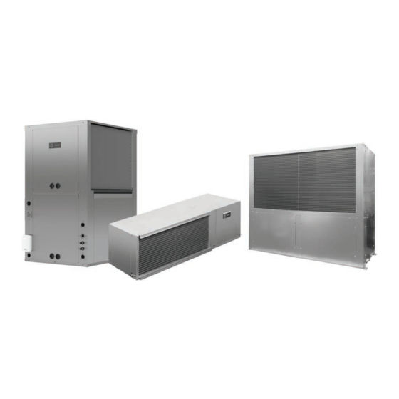
Axiom™ ™ Horizontal/Vertical —
GEH/V*
0.5 to 25 Tons, 50/60 Hz
Model Numbers:
GEHE 006-060 - 50/60 Hz
GEVG 006-060 - 60 Hz
GEHE 072-180 - 50/60 Hz
GEVE 072-300 - 50/60 Hz
Only qualified personnel should install and service the equipment. The installation, starting up, and servicing of heating, ventilating, and air-conditioning
equipment can be hazardous and requires specific knowledge and training. Improperly installed, adjusted or altered equipment by an unqualified person
could result in death or serious injury. When working on the equipment, observe all precautions in the literature and on the tags, stickers, and labels that
are attached to the equipment.
August 2021
S S A A F F E E T T Y Y W W A A R R N N I I N N G G
W W S S H H P P - - S S V V X X 0 0 1 1 Y Y - - E E N N
Advertisement
Table of Contents

Subscribe to Our Youtube Channel
Related Manuals for Trane Axiom GEH-E006


Summary of Contents for Trane Axiom GEH-E006
- Page 1 Installation, Operation, and Maintenance Water Source Heat Pump Axiom™ ™ Horizontal/Vertical — GEH/V* 0.5 to 25 Tons, 50/60 Hz Model Numbers: GEHE 006-060 - 50/60 Hz GEVG 006-060 - 60 Hz GEHE 072-180 - 50/60 Hz GEVE 072-300 - 50/60 Hz S S A A F F E E T T Y Y W W A A R R N N I I N N G G Only qualified personnel should install and service the equipment.
- Page 2 A A L L W W A A Y Y S S r r e e f f e e r r t t o o a a p p p p r r o o p p r r i i a a t t e e S S a a f f e e t t y y D D a a t t a a impact to the environment. Trane advocates the...
- Page 3 This document and the information in it are the property of Trane, and may not be used or reproduced F F a a i i l l u u r r e e t t o o f f o o l l l l o o w w i i n n s s t t r r u u c c t t i i o o n n s s b b e e l l o o w w c c o o u u l l d d r r e e s s u u l l t t i i n n in whole or in part without written permission.
-
Page 4: Table Of Contents
Table of Contents Model Number Description ....6 General Installation Checks ....44 GEV Models. - Page 5 T T a a b b l l e e o o f f C C o o n n t t e e n n t t s s Waterside Economizer Installation for Water Pressure Drop ....107 Vertical 0.5–5 ton Units .
-
Page 6: Model Number Description
Model Number Description Digits 1–3 — Unit Configuration Digit 11 — Refrigeration Circuit Digit 18 — Tstat/Sensor Location GEH = Standard Efficiency Horizontal 0.5 to 0 = Heating and Cooling Circuit 0 = Wall Mounted Location 15 Tons 2 = Heating and Cooling Circuit with Hot Gas GEV = Standard Efficiency Vertical 6 to 25 Reheat Digit 19 —... -
Page 7: Gev Models
M M o o d d e e l l N N u u m m b b e e r r D D e e s s c c r r i i p p t t i i o o n n GEV Models Digits 1–3 —... -
Page 8: Overview Of Manual
Overview of Manual N N o o t t e e : : One copy of this document ships inside the includes the unit model number, serial number, control panel of each unit and is customer electrical characteristics, refrigerant charge, and other property. -
Page 9: General Information
The control operation. Trane microprocessor board is factory wired to a terminal strip to provide all necessary terminals for field connection. The deluxe board is equipped with a... -
Page 10: Boilerless Control/Electric Heat
G G e e n n e e r r a a l l I I n n f f o o r r m m a a t t i i o o n n provided for field installation on the entering water space), the humidistat signals the reheat relay coil to side of the coil. - Page 11 G G e e n n e e r r a a l l I I n n f f o o r r m m a a t t i i o o n n Table 3. Refrigerant charge (continued) Table 3.
-
Page 12: Pre-Installation
Pre-Installation W W A A R R N N I I N N G G is stored. Concealed damage must be reported within 15 days. F F i i b b e e r r g g l l a a s s s s W W o o o o l l ! ! •... - Page 13 P P r r e e - - I I n n s s t t a a l l l l a a t t i i o o n n possible IAQ contaminant sources from growing, the the unit(s) surfaces. Wet interior unit insulation can unit should be stored indoors.
-
Page 14: Unit Dimensions
Unit Dimensions Service Clearances and safe operation and maintenance of such equipment. Local codes may require more clearance to Per NEC requirements, 36 inches of access and working electrical equipment. Check all code requirements prior space shall be provided and maintained around all to unit installation. - Page 15 U U n n i i t t D D i i m m e e n n s s i i o o n n s s A 24 inch clearance from other mechanical and electrical equipment Figure 3. Clearance – GEV .5 to 5 tons (where shown) is recommended for most unit configurations.
-
Page 16: Dimensional Data
U U n n i i t t D D i i m m e e n n s s i i o o n n s s Dimensional Data Figure 6. Left return/left supply (GEHE) F X G OPENING COMP/CONTROL ACCESS BLOWER... - Page 17 U U n n i i t t D D i i m m e e n n s s i i o o n n s s Table 5. Dimensional data left return/back supply (GEHE) Unit Unit F x G NPTI NPTI (60 Hz)
- Page 18 U U n n i i t t D D i i m m e e n n s s i i o o n n s s Figure 9. Right return/left supply (GEHE) F X G BLOWER COMP/CONTROL OPENING ACCESS ACCESS PANEL...
- Page 19 U U n n i i t t D D i i m m e e n n s s i i o o n n s s Table 8. Dimensional data right return/back supply (GEHE) Unit Unit F x G NPTI NPTI (60 Hz)
- Page 20 U U n n i i t t D D i i m m e e n n s s i i o o n n s s Figure 12. Left return/top supply (GEVG) Table 10. Dimensional data left return/top supply (GEVG) Blower Duct Cabinet...
- Page 21 U U n n i i t t D D i i m m e e n n s s i i o o n n s s Figure 14. Right return/left supply - GEHE 6 to 10 tons (60 Hz); GEHE 6 to 7.5 tons (50 Hz) 79”...
- Page 22 U U n n i i t t D D i i m m e e n n s s i i o o n n s s Figure 15. Right return/back supply - GEHE 6 to 10 tons (60 Hz); GEHE 6 to 7.5 tons (50 Hz) 79”...
- Page 23 U U n n i i t t D D i i m m e e n n s s i i o o n n s s Figure 16. Left return/right supply GEHE 6 to 10 tons (60 Hz); GEHE 6 to 7.5 tons (50 Hz) 79”...
- Page 24 U U n n i i t t D D i i m m e e n n s s i i o o n n s s Figure 17. Left return/back supply GEHE 6 to 10 tons (60 Hz); GEHE 6 to 7.5 tons (50 Hz) 79”...
- Page 25 U U n n i i t t D D i i m m e e n n s s i i o o n n s s Figure 18. Right return/back supply GEHE 12.5 to 15 Figure 20. Left return/back supply GEHE 12.5 to 15 tons (60 Hz);...
- Page 26 U U n n i i t t D D i i m m e e n n s s i i o o n n s s Figure 21. Front return/back supply GEVE 6 to 10 tons (60 Hz); 6 and 7.5 tons (50 Hz) SUPPLY OPENING 15 3/4”...
- Page 27 U U n n i i t t D D i i m m e e n n s s i i o o n n s s Figure 22. Front return/top supply GEVE 6 to 10 tons (60 Hz); 6 and 7.5 tons (50 Hz) ACCESS PANEL FOR 15 5/8 SHEAVES AND BELTS...
- Page 28 U U n n i i t t D D i i m m e e n n s s i i o o n n s s Figure 23. Back return/front supply GEVE 6 to 10 tons (60 Hz); 6 and 7.5 tons (50 Hz) 39 5/8"...
- Page 29 U U n n i i t t D D i i m m e e n n s s i i o o n n s s Figure 24. Back return/top supply GEVE 6 to 10 tons (60 Hz); 6 and 7.5 tons (50 Hz) 39 5/8"...
- Page 30 U U n n i i t t D D i i m m e e n n s s i i o o n n s s Figure 25. Front return/back supply GEVE 12.5 to 15 Figure 26. Back return/front supply GEV 12.5 to 15 tons (60 Hz);...
- Page 31 U U n n i i t t D D i i m m e e n n s s i i o o n n s s Figure 27. Front return/top supply GEVE 12.5 to 15 Figure 28. Back return/top supply GEVE 12.5 to 15 tons (60 Hz);...
- Page 32 U U n n i i t t D D i i m m e e n n s s i i o o n n s s Figure 29. Front return/back supply GEVE 20 and 25 tons (60 Hz); GEVE 15 and 20 tons (50 Hz) 31 1/2"...
- Page 33 U U n n i i t t D D i i m m e e n n s s i i o o n n s s Figure 30. Back return/front supply GEVE 20 and 25 tons (60 Hz); GEVE 15 and 20 tons (50 Hz) 81 5/8"...
- Page 34 U U n n i i t t D D i i m m e e n n s s i i o o n n s s Figure 31. Front return/top supply GEVE 20 and 25 tons (60 Hz); GEVE 15 and 20 tons (50 Hz) 31 1/2"...
- Page 35 U U n n i i t t D D i i m m e e n n s s i i o o n n s s Figure 32. Back return/top supply GEVE 20 and 25 tons (60 Hz); GEVE 15 and 20 tons (50 Hz) 81 5/8"...
- Page 36 U U n n i i t t D D i i m m e e n n s s i i o o n n s s Figure 33. Waterside economizer (GEHE) TOP VIEW 20" A = TO FIELD SUPPLY PIPING B = TO FIELD RETURN PIPING...
- Page 37 U U n n i i t t D D i i m m e e n n s s i i o o n n s s Figure 34. Waterside economizer (GEVG) Table 25. Dimensional data waterside economizer (GEVG) WSE Dimensions Unit Cabinet...
- Page 38 U U n n i i t t D D i i m m e e n n s s i i o o n n s s Figure 35. Waterside economizer (GEVG) Table 26. Dimensional data waterside economizer (GEVG) Pipe Size Piping Location WSE Size...
- Page 39 U U n n i i t t D D i i m m e e n n s s i i o o n n s s Table 27. Dimensional data hanging unit waterside economizer (GEH) GEH Unit GEH Unit Hanging Weight Shipping Weight (60 Hz) (50 Hz)
- Page 40 U U n n i i t t D D i i m m e e n n s s i i o o n n s s Table 29. Dimensional data GEHE 12.5 to 15 tons (60 Hz), GEHE 10 to 12.5 tons (50 Hz), right return with waterside economizer GEHE (60 Hz) GEHE (50 Hz)
- Page 41 U U n n i i t t D D i i m m e e n n s s i i o o n n s s Figure 41. GEVE 6 to 10 tons (60 Hz), 6 and 7.5 tons (50 Hz) - waterside economizer A = TO FIELD RETURN PIPING...
- Page 42 U U n n i i t t D D i i m m e e n n s s i i o o n n s s Table 32. Dimensional data GEVE 12.5 to 25 tons - waterside economizer Hanging GEVE (60 Hz) GEVE (50 Hz)
-
Page 43: Weights
Weights Weight Distribution for Hanging Table 33. Unit weights GEH 0.5 to 5 tons (Approximate) the GEH Model Shipping Unit Weight W W A A R R N N I I N N G G Weight with without pallet GEH (60 Hz) pallet (lbs) (lbs) I I m m p p r r o o p p e e r r U U n n i i t t L L i i f f t t ! ! -
Page 44: Installation
Installation Main Electrical W W A A R R N N I I N N G G P P r r o o p p e e r r F F i i e e l l d d W W i i r r i i n n g g a a n n d d G G r r o o u u n n d d i i n n g g W W A A R R N N I I N N G G R R e e q q u u i i r r e e d d ! ! H H a a z z a a r r d d o o u u s s V V o o l l t t a a g g e e ! ! -
Page 45: Supply-Air Ductwork
I I n n s s t t a a l l l l a a t t i i o o n n N N o o t t e e : : Do not operate the unit without filters. Figure 47. -
Page 46: Ducted Filter Rack
I I n n s s t t a a l l l l a a t t i i o o n n Figure 48. Return-air duct panel Table 36. Ducted panel — return air GEVG Unit Top Duct Collar Unit Size A (in.) B (in.) -
Page 47: Dual Filtration (Geh 0.5 To 5 Ton)
I I n n s s t t a a l l l l a a t t i i o o n n Hanging the Horizontal Unit Table 37. Ducted filter opening size GEH/V (continued) W W A A R R N N I I N N G G A (in.) B (in.) C (in.) -
Page 48: Condensate Drain Connection
I I n n s s t t a a l l l l a a t t i i o o n n Condensate Drain Connection N N o o t t e e : : Above figure example incorporates the Hays Mesurflo®... -
Page 49: Field Installed Power Wiring
I I n n s s t t a a l l l l a a t t i i o o n n Field Installed Power Wiring Figure 52. Power wiring example W W A A R R N N I I N N G G P P r r o o p p e e r r F F i i e e l l d d W W i i r r i i n n g g a a n n d d G G r r o o u u n n d d i i n n g g R R e e q q u u i i r r e e d d ! ! F F a a i i l l u u r r e e t t o o f f o o l l l l o o w w c c o o d d e e c c o o u u l l d d r r e e s s u u l l t t i i n n d d e e a a t t h h o o r r... -
Page 50: Thermostats And Zone Sensors
I I n n s s t t a a l l l l a a t t i i o o n n • Behind doors or corners • Near concealed pipes or chimneys • Near hot or cold air ducts •... - Page 51 COMM module to service technicians. Tracer® ZN524 and UC400 Compatible X13651467020 Communication Module • Sold in packs of 12 • Provides local RJ22 connection to Trane® service tools for easy, low cost maintenance. X13511529010 Zone Sensor • Tracer® UC400 and ZN524 compatible •...
- Page 52 I I n n s s t t a a l l l l a a t t i i o o n n Table 39. Zone sensor selection for use with Tracer® ® ZN524 and UC400 controller (continued) Description Sensor Part Number X1379084501...
-
Page 53: Controls Using 24 Vac
I I n n s s t t a a l l l l a a t t i i o o n n Table 40. Wireless zone sensor selection for use with Tracer® ® UC400 controller Description Sensor Part Number X13790955040 Trane Air-Fi® WCS-SD (display) • Tracer® UC400 Compatible • Easy-to-use interface for clear and simple monitoring and control X13790956010 Trane Air-Fi®... - Page 54 I I n n s s t t a a l l l l a a t t i i o o n n Figure 55. Low-voltage connection (GEH/V 6 to 25 Figure 57. Deluxe controls with WSE or DX two-stage ton) Deluxe Controls with Deluxe Controls with...
-
Page 55: External Smoke Detection Wiring To
I I n n s s t t a a l l l l a a t t i i o o n n External Smoke Detection Figure 59. Deluxe controls general alarm and compressor disable Wiring to Unit Deluxe Controller To inhibit operation of the compressor and fan for a safety shutdown, it is necessary to break the wire (21X) from the 24Volt transformer to the 1TB1 terminal block. -
Page 56: Removing Speed-Tap Wire
I I n n s s t t a a l l l l a a t t i i o o n n W W A A R R N N I I N N G G Table 43. 3-speed motor (380, 415, 460) P P r r o o p p e e r r F F i i e e l l d d W W i i r r i i n n g g a a n n d d G G r r o o u u n n d d i i n n g g Lead Colors R R e e q q u u i i r r e e d d ! ! -
Page 57: Vertical 0.5-5 Tons - Units With Deluxe 24V Or Tracer® Zn524
I I n n s s t t a a l l l l a a t t i i o o n n Figure 61. Fan motor and sheave adjustment Figure 63. ECM control board 1. Potentiometer will be used to adjust the PWM 1. - Page 58 6. Install the SUPPLY and RETURN hoses to the: package fits to the outside of the of the water- a. position valve’s threaded connection. source heat pump. Trane recommends the mating of the systems be made via 3-screws spaced evenly b. water-out threaded connection of the water- across the top, 3-screws spaced evenly across the source heat pump.
- Page 59 I I n n s s t t a a l l l l a a t t i i o o n n Figure 67. Step 6 Figure 69. Step 8 9. Wire-tie the sensor to the water SUPPLY side of the 7.
- Page 60 I I n n s s t t a a l l l l a a t t i i o o n n Figure 71. Step 10 Figure 73. Step 12 13. Bundle excess valve wire, and wire tie the bundle neatly.
-
Page 61: Waterside Economizer Installation For Vertical 0.5-5 Ton Units
N N o o t t e e s s : : 1. Remove the filter bracket from the unit. It is secured • Trane does not provide insulation on the by five screws: three on top (circled) and two on the economizing piping package. This insulation bottom (not shown). - Page 62 N N o o t t e e s s : : • Trane does not provide insulation on the economizing piping package. This insulation must be field provided and field installed.
-
Page 63: Waterside Economizer Installation
/ / n n a a t t i i o o n n a a l l e e l l e e c c t t r r i i c c a a l l c c o o d d e e s s . . • Trane does not provide insulation on the 1. Remove the filter frame from the unit. - Page 64 I I n n s s t t a a l l l l a a t t i i o o n n condensate to spit or build-up in the economizer or unit to installing a condensate trap. See Condensate Drain drain pans.
-
Page 65: Sequence
Waterside Economizer Start-Up Sequence 1. Set the thermostat to the highest position. 6. Leave unit off for approximately FIVE minutes to allow for pressure equalization. 2. Set the thermostat system switch to COOL with the fan control to AUTO. The compressor should NOT 7. - Page 66 W W a a t t e e r r s s i i d d e e E E c c o o n n o o m m i i z z e e r r S S t t a a r r t t - - U U p p S S e e q q u u e e n n c c e e Table 47.
-
Page 67: Electrical Data
Electrical Data WSHP-SVX01Y-EN... - Page 68 E E l l e e c c t t r r i i c c a a l l D D a a t t a a WSHP-SVX01Y-EN...
- Page 69 E E l l e e c c t t r r i i c c a a l l D D a a t t a a WSHP-SVX01Y-EN...
- Page 70 E E l l e e c c t t r r i i c c a a l l D D a a t t a a WSHP-SVX01Y-EN...
- Page 71 E E l l e e c c t t r r i i c c a a l l D D a a t t a a WSHP-SVX01Y-EN...
- Page 72 E E l l e e c c t t r r i i c c a a l l D D a a t t a a WSHP-SVX01Y-EN...
- Page 73 E E l l e e c c t t r r i i c c a a l l D D a a t t a a WSHP-SVX01Y-EN...
- Page 74 E E l l e e c c t t r r i i c c a a l l D D a a t t a a WSHP-SVX01Y-EN...
- Page 75 E E l l e e c c t t r r i i c c a a l l D D a a t t a a WSHP-SVX01Y-EN...
- Page 76 E E l l e e c c t t r r i i c c a a l l D D a a t t a a WSHP-SVX01Y-EN...
- Page 77 E E l l e e c c t t r r i i c c a a l l D D a a t t a a WSHP-SVX01Y-EN...
- Page 78 E E l l e e c c t t r r i i c c a a l l D D a a t t a a WSHP-SVX01Y-EN...
- Page 79 E E l l e e c c t t r r i i c c a a l l D D a a t t a a WSHP-SVX01Y-EN...
- Page 80 E E l l e e c c t t r r i i c c a a l l D D a a t t a a WSHP-SVX01Y-EN...
- Page 81 E E l l e e c c t t r r i i c c a a l l D D a a t t a a WSHP-SVX01Y-EN...
- Page 82 E E l l e e c c t t r r i i c c a a l l D D a a t t a a WSHP-SVX01Y-EN...
- Page 83 E E l l e e c c t t r r i i c c a a l l D D a a t t a a WSHP-SVX01Y-EN...
- Page 84 E E l l e e c c t t r r i i c c a a l l D D a a t t a a WSHP-SVX01Y-EN...
- Page 85 E E l l e e c c t t r r i i c c a a l l D D a a t t a a WSHP-SVX01Y-EN...
- Page 86 E E l l e e c c t t r r i i c c a a l l D D a a t t a a WSHP-SVX01Y-EN...
- Page 87 E E l l e e c c t t r r i i c c a a l l D D a a t t a a WSHP-SVX01Y-EN...
- Page 88 E E l l e e c c t t r r i i c c a a l l D D a a t t a a Table 52. Electrical minimum and maximum 0.5 to 25 tons Min Utiliz. Max Utiliz.
- Page 89 E E l l e e c c t t r r i i c c a a l l D D a a t t a a Table 52. Electrical minimum and maximum 0.5 to 25 tons (continued) Min Utiliz. Max Utiliz.
-
Page 90: Pre-Start Checklist
Pre-Start Checklist Before energizing the unit, the following system • Are the low/high-side pressure temperature caps devices must be checked: secure and in place? • Is the high voltage power supply correct and in • Are all the unit access panels secure and in place? accordance with the nameplate ratings? •... -
Page 91: Start Up
Start Up Initial Unit Start-Up Table 53. Checklist (continued) N N o o t t e e : : Start-up with the heat pump thermostat is MODE Heat Cool included below: Return-air temperature DB/ 1. Set the thermostat to the highest position. _______F _______F 2. - Page 92 S S t t a a r r t t U U p p Table 54. Operating pressures in cooling/heating for GE units Operating Data Cooling Heating Entering Water Water Dis- Dis- Water Suction Water Air Temp Suction Air Temp Flow Model charge...
- Page 93 S S t t a a r r t t U U p p Table 54. Operating pressures in cooling/heating for GE units (continued) Operating Data Cooling Heating Entering Water Water Dis- Dis- Water Suction Water Air Temp Suction Air Temp Flow Model charge...
- Page 94 S S t t a a r r t t U U p p Table 54. Operating pressures in cooling/heating for GE units (continued) Operating Data Cooling Heating Entering Water Water Dis- Dis- Water Suction Water Air Temp Suction Air Temp Flow Model charge...
- Page 95 S S t t a a r r t t U U p p Table 54. Operating pressures in cooling/heating for GE units (continued) Operating Data Cooling Heating Entering Water Water Dis- Dis- Water Suction Water Air Temp Suction Air Temp Flow Model charge...
- Page 96 S S t t a a r r t t U U p p Table 54. Operating pressures in cooling/heating for GE units (continued) Operating Data Cooling Heating Entering Water Water Dis- Dis- Water Suction Water Air Temp Suction Air Temp Flow Model charge...
- Page 97 S S t t a a r r t t U U p p Table 54. Operating pressures in cooling/heating for GE units (continued) Operating Data Cooling Heating Entering Water Water Dis- Dis- Water Suction Water Air Temp Suction Air Temp Flow Model charge...
- Page 98 S S t t a a r r t t U U p p Table 54. Operating pressures in cooling/heating for GE units (continued) Operating Data Cooling Heating Entering Water Water Dis- Dis- Water Suction Water Air Temp Suction Air Temp Flow Model charge...
- Page 99 S S t t a a r r t t U U p p Table 54. Operating pressures in cooling/heating for GE units (continued) Operating Data Cooling Heating Entering Water Water Dis- Dis- Water Suction Water Air Temp Suction Air Temp Flow Model charge...
- Page 100 S S t t a a r r t t U U p p Table 54. Operating pressures in cooling/heating for GE units (continued) Operating Data Cooling Heating Entering Water Water Dis- Dis- Water Suction Water Air Temp Suction Air Temp Flow Model charge...
- Page 101 S S t t a a r r t t U U p p Table 54. Operating pressures in cooling/heating for GE units (continued) Operating Data Cooling Heating Entering Water Water Dis- Dis- Water Suction Water Air Temp Suction Air Temp Flow Model charge...
- Page 102 S S t t a a r r t t U U p p Table 54. Operating pressures in cooling/heating for GE units (continued) Operating Data Cooling Heating Entering Water Water Dis- Dis- Water Suction Water Air Temp Suction Air Temp Flow Model charge...
- Page 103 S S t t a a r r t t U U p p Table 54. Operating pressures in cooling/heating for GE units (continued) Operating Data Cooling Heating Entering Water Water Dis- Dis- Water Suction Water Air Temp Suction Air Temp Flow Model charge...
- Page 104 S S t t a a r r t t U U p p Table 54. Operating pressures in cooling/heating for GE units (continued) Operating Data Cooling Heating Entering Water Water Dis- Dis- Water Suction Water Air Temp Suction Air Temp Flow Model charge...
- Page 105 S S t t a a r r t t U U p p Table 54. Operating pressures in cooling/heating for GE units (continued) Operating Data Cooling Heating Entering Water Water Dis- Dis- Water Suction Water Air Temp Suction Air Temp Flow Model charge...
- Page 106 S S t t a a r r t t U U p p Table 54. Operating pressures in cooling/heating for GE units (continued) Operating Data Cooling Heating Entering Water Water Dis- Dis- Water Suction Water Air Temp Suction Air Temp Flow Model charge...
-
Page 107: Water Pressure Drop
S S t t a a r r t t U U p p Table 54. Operating pressures in cooling/heating for GE units (continued) Operating Data Cooling Heating Entering Water Water Dis- Dis- Water Suction Water Air Temp Suction Air Temp Flow Model charge... -
Page 108: Water Volume
S S t t a a r r t t U U p p Table 56. Heating water pressure drop (WPD) in feet Table 57. Water volume for GE* units of head for * GE units (continued) Water Water Water Side Unit Size Unit Size... -
Page 109: Maintenance
Maintenance W W A A R R N N I I N N G G Table 58. Filter sizing GE* models (continued) H H a a z z a a r r d d o o u u s s S S e e r r v v i i c c e e P P r r o o c c e e d d u u r r e e s s ! ! Size (50 Filter Size (Nominal) Size (60 Hz) -
Page 110: Condensate Trap
M M a a i i n n t t e e n n a a n n c c e e W W A A R R N N I I N N G G Table 59. Water quality (continued) H H a a z z a a r r d d o o u u s s C C h h e e m m i i c c a a l l s s ! ! Scaling Amount... -
Page 111: Troubleshooting
Troubleshooting Deluxe Controls W W A A R R N N I I N N G G H H a a z z a a r r d d o o u u s s S S e e r r v v i i c c e e P P r r o o c c e e d d u u r r e e s s ! ! Troubleshooting units which contain the deluxe control option may be made easy by using the three LEDs F F a a i i l l u u r r e e t t o o f f o o l l l l o o w w a a l l l l p p r r e e c c a a u u t t i i o o n n s s i i n n t t h h i i s s m m a a n n u u a a l l a a n n d d... - Page 112 T T r r o o u u b b l l e e s s h h o o o o t t i i n n g g Table 61. Troubleshooting table Hea- Cool- Problem Cause Correction ting Main power off Check fuses Replace...
- Page 113 T T r r o o u u b b l l e e s s h h o o o o t t i i n n g g Table 61. Troubleshooting table (continued) Hea- Cool- Problem Cause Correction ting Trash in heat exchanger Backflush...
-
Page 114: Wiring Diagrams
Wiring Diagrams This section contains wiring diagrams and isolation N N o o t t e e : : Wiring diagrams can be accessed via e-Library valve wiring connections. by entering the diagram number in the literature order number search field or by calling technical Table 62. - Page 115 W W i i r r i i n n g g D D i i a a g g r r a a m m s s Figure 82. GEH_V (6 to 25 tons) - deluxe 380V - 420V - 50 Hz - 3 ph ISOLATED GENERAL ALARM CONTACTS.
- Page 116 W W i i r r i i n n g g D D i i a a g g r r a a m m s s Figure 83. GEH_V (6 to 25 tons) - deluxe 24V - 460V - 60 Hz - 3 ph WSHP-SVX01Y-EN...
- Page 117 W W i i r r i i n n g g D D i i a a g g r r a a m m s s Figure 84. GEH_V (6 to 25 tons) - Tracer® ZN524 460V - 60 Hz - 3 ph WSHP-SVX01Y-EN...
- Page 118 W W i i r r i i n n g g D D i i a a g g r r a a m m s s Figure 85. GEHE (0.5 to 1.5 tons) - UC400 WSHP-SVX01Y-EN...
- Page 119 W W i i r r i i n n g g D D i i a a g g r r a a m m s s Figure 86. GEHE (2 to 5 tons) - UC400 WSHP-SVX01Y-EN...
- Page 120 7VA MAX LOAD AT 24 VAC. AND AFTER A NORMAL SHUTDOWN HAS OCCURRED. COMMUNICATION WIRE MUST BE TRANE PART NO. WIRES USED FOR CURRENT SENSING SWITCH OPTION ONLY 400-20-28, OR WINDY CITY OR CONNECT AIR DASHED LINES INDICATE RECOMMENDED FIELD "LEVEL 4"...
-
Page 121: Warranty Information
The optional extended warranty is a second through fifth year warranty. The time starts at the end of the Trane’s parts-only warranty, running 12 months from startup, not to exceed 18-months from shipment. standard 1 year coverage through the fifth year. - Page 122 N N o o t t e e s s WSHP-SVX01Y-EN...
- Page 123 N N o o t t e e s s WSHP-SVX01Y-EN...
- Page 124 For more information, please visit trane.com or tranetechnologies.com. Trane has a policy of continuous product and product data improvements and reserves the right to change design and specifications without notice. We are committed to using environmentally conscious print practices.
Need help?
Do you have a question about the Axiom GEH-E006 and is the answer not in the manual?
Questions and answers