Table of Contents
Advertisement
Quick Links
Advertisement
Table of Contents

Subscribe to Our Youtube Channel
Related Manuals for LeCroy ArbStudio

Summary of Contents for LeCroy ArbStudio
- Page 1 ArbStudio Arbitrary Waveform Generator Getting Started Manual April, 2010 ...
- Page 2 LeCroy Corporation 700 Chestnut Ridge Road Chestnut Ridge, NY, 10977‐6499 Tel: (845) 578‐6020, Fax: (845) 578 5985 Warranty NOTE: THE WARRANTY BELOW REPLACES ALL OTHER WARRANTIES, EXPRESSED OR IMPLIED, INCLUDING BUT NOT LIMITED TO ANY IMPLIED WARRANTY OF MERCHANTABILITY, FITNESS, OR ADEQUACY FOR ANY PARTICULAR PURPOSE OR USE. LECROY SHALL NOT BE LIABLE FOR ANY SPECIAL, INCIDENTAL, OR CONSEQUENTIAL DAMAGES, WHETHER IN CONTRACT OR OTHERWISE. THE CUSTOMER IS RESPONSIBLE FOR THE TRANSPORTATION AND INSURANCE CHARGES FOR THE RETURN OF PRODUCTS TO THE SERVICE FACILITY. LECROY WILL RETURN ALL PRODUCTS UNDER WARRANTY WITH TRANSPORT PREPAID. The instrument is warranted for normal use and operation, within specifications, for a period of three years from shipment. LeCroy will either repair or, at our option, replace any product returned to one of our authorized service centers within this period. However, in order to do this we must first examine the product and find that it is defective due to workmanship or materials and not due to misuse, neglect, accident, or abnormal conditions or operation. LeCroy shall not be responsible for any defect, damage, or failure caused by any of the following: a) attempted repairs or installations by personnel other than LeCroy representatives or b) improper connection to incompatible equipment, or c) for any damage or malfunction caused by the use of non‐LeCroy supplies. Furthermore, LeCroy shall not be obligated to service a product that has been modified or integrated where the modification or integration increases the task duration or difficulty of servicing the instrument. Spare and replacement parts, and repairs, all have a 90‐day warranty. The instrument firmware has been thoroughly tested and is presumed to be functional. Nevertheless, it is supplied without warranty of any kind covering detailed performance. Products not made by LeCroy are covered solely by the warranty of the original equipment manufacturer. Internet: www.lecroy.com © 2010 LeCroy Corporation by . All rights reserved. LeCroy, ActiveDSO, JitterTrack, WavePro, WaveMaster, WaveSurfer, WaveLink, WaveExpert, Waverunner, and WaveAce are registered trademarks of LeCroy Corporation. Other product or brand names are trademarks or requested trademarks of their respective holders. Information in this publication supersedes all earlier versions. Specifications are subject to change without notice. This electronic product is subject to disposal and recycling regulations that vary by country and region. Many Manufactured under an ISO 9000 ...
-
Page 3: Table Of Contents
Front Panel ......................... 1 1 DIGITAL POD A / DIGITAL POD B ................ 1 1 Back Panel ........................ 1 2 Making Expansion Bus Connections ................ 1 2 Removing Expansion Bus Connections .............. 1 2 Getting Started with ArbStudio ................. 1 3 Overview ........................ 1 3 Software and Driver Installation ................ 1 3 Software Installation .................... 1 3 Driver Installation ...................... 1 6 ... - Page 4 ArbStudio Continuous ......................... 3 7 Burst (DDS Only) ...................... 3 7 Channel Settings ‐ The Trigger IN Tab ................ 3 8 Source Connector ...................... 3 8 Edge ........................... 3 8 Action ......................... 3 8 Channel Settings ‐ Trigger OUT Tab ................ 3 9 Trigger out source ...................... 3 9 Setup System ...................... 40 Setup Device ...................... 4 1 Overview ........................ 4 1 ...
- Page 5 Getting Started Manual Noise .......................... 6 2 Markers ........................ 6 3 Sequencing Analog Waveforms ................. 6 5 Editing a Sequence ..................... 6 5 Additional Waveform Sequencer Settings and Tools .......... 6 7 Zoom .......................... 6 7 Waveform View Settings ................... 6 7 Signals Property Settings ................... 6 8 Cursors ........................ 6 8 Go To a Selected Target ..................... 7 0 Search ........................ 7 0 Modulation Editor (Arbitrary/DDS) ................ ...
- Page 6 ArbStudio Sequencing Digital Waveforms ................ 1 07 Signal Definitions ..................... 1 07 Adding a signal ...................... 1 08 Adding a bus ...................... 1 08 Removing a signal or a bus .................. 1 09 Editing a signal or bus name .................. 1 09 Acquisition ‐ Using The Pattern Generator as a Sampler ........ 1 09 The Waveform View Screen .................. 1 09 The State Listing Screen ................... 1 11 Probes ........................ 1 16 Signal Description (Arbitrary/DDS Mode) .............. 1 17 ...
-
Page 7: Introduction
• 150 MBytes hard disk available space for software set‐up. • Video resolution 800 X 600. • USB 2.0 or 1.1 connections. Suggested System Requirements • Operative system Microsoft™ Windows® XP, Windows® Vista 32 Bit Version, Windows® 7 32 Bit Version. • Pentium® IV processor. • 1.5 GBytes RAM. • Video resolution 1024 X 768. • USB 2.0 connection. Package Contents The standard ArbStudio 1102/1104 package includes the following: • ArbStudio 1102/1104 Arbitrary Waveform Generator • Standard USB 2.0 Cable • Power Supply Adapter • Power Cord • Installation CD containing the ArbStudio Software setup files, ArbStudio Function Generator software, Drivers, and the Getting Started Manual. • Performance/Calibration Certificate • ArbStudio Introduction and Compliance document • ‐D Models include a ‘Digital Leadset’ 918221 RevA ... -
Page 8: Safety Requirements
ArbStudio Safety Requirements This section contains information and warnings that must be observed to keep the instrument operating in a correct and safe condition. You are required to follow generally accepted safety procedures in addition to the safety precautions specified in this section. Safety Symbols Where the following symbols appear on the instrument’s front or rear panels, or in this manual, they alert you to important safety considerations. This symbol is used where caution is required. Refer to the accompanying information or documents in order to protect against personal injury or damage to the instrument. This symbol warns of a potential risk of shock hazard. This symbol is used to denote the measurement ground connection. This symbol is used to denote a frame or chassis connection. This symbol is used to denote a safety ground connection. On (Supply). This is the DC power connect/disconnect switch at the back of the instrument. Off (Supply). This is the DC power connect/disconnect switch at the back of the instrument. This symbol is used to denote Power. It is located on the front panel and denotes Power On/Off status of the instrument. 8 918221 RevA... - Page 9 Getting Started Manual This symbol is used to denote Direct Current. CAUTION The CAUTION sign indicates a potential hazard. It calls attention to a procedure, practice or condition which, if not followed, could possibly cause damage to equipment. If a CAUTION is indicated, do not proceed until its conditions are fully understood and met. WARNING The WARNING sign indicates a potential hazard. It calls attention to a procedure, practice or condition which, if not followed, could possibly cause bodily injury or death. If a WARNING is indicated, do not proceed until its conditions are fully understood and met. CAT I Installation (Overvoltage) Category rating per EN 61010‐1 safety standard and is applicable for the instrument front panel measuring terminals. CAT I rated terminals must only be connected to source circuits in which measures are taken to limit transient voltages to an appropriately low level. Operating Environment The instrument is intended for indoor use and should be operated in a clean, dry environment. Before using this product, ensure that its operating environment is maintained within these parameters: Temperature: 0 °C to 50 °C (Note: Power Supply Adapter for ArbStudio 1104 is rated for 40 °C max). Humidity: Maximum relative humidity 80% (non‐condensing) for temperatures up to 40 °C decreasing linearly to 50 % relative humidity at 50 °C. Altitude: Up to 10,000 ft (3,048 m) at or below 30 °C. Note: Direct sunlight, radiators, and other heat sources should be taken into account when assessing the ambient temperature. WARNING The instrument must not be operated in explosive, dusty, or wet atmospheres. CAUTION Do not exceed the maximum specified front panel terminal voltage levels. Refer to Specifications for more details. Cooling The instrument relies on forced air cooling with an internal fan and ventilation openings. Care must be taken to avoid restricting the airflow around the apertures (fan holes) at the side of the instrument. CAUTION 918221 RevA ...
-
Page 10: Abnormal Conditions
ArbStudio Do not allow any foreign matter to enter the instrument through the ventilation holes, etc. AC Power Source For External AC Adapter: 100 to 240 VAC (+/‐10%) at 45‐66 Hz; Automatic AC voltage selection; Installation Category: 300V CAT II No manual voltage selection is required because the external AC Adapter automatically adapts to line voltage. Power Consumption </= 30 watts (12 V at 2.5 amps) WARNING ‐ Electrical Shock Hazard Only use the power cord provided with your instrument. Calibration The recommended calibration interval is one year. Calibration should be performed by qualified personnel only. Cleaning Clean only the exterior of the instrument, using a damp, soft cloth. Do not use chemicals or abrasive elements. Under no circumstances allow moisture to penetrate the instrument. Abnormal Conditions Operate the instrument only as intended by the manufacturer. If you suspect the instrument’s protection has been impaired, disconnect the power cord and secure the instrument against any unintended operation. The instrument’s protection is likely to be impaired if, for example, the instrument shows visible damage or has been subjected to severe transport stresses. Proper use of the instrument depends on careful reading of all instructions and labels. WARNING Any use of the instrument in a manner not specified by the manufacturer may impair the instrument’s safety protection. 10 918221 RevA... -
Page 11: Front Panel
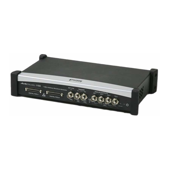
Getting Started Manual Front Panel Numbered callouts on this image correspond with the following descriptions. Figure 3‐1. This is an image of the ArbStudio 1104 model and therefore has a POD B connector and two additional Channel Outputs. Although digital pods appear on all models, they are only active on 1102D and 1104D models. DIGITAL POD A / DIGITAL POD B 1. DIGITAL POD A / DIGITAL POD B • Pod A and Pod B – Digital probe connectors. Note: DIGITAL POD B is only available on ArbStudio 1104. POD A and POD B are only active on 1102D and 1104D models. ArbStudio 1102 and 1104 can be upgraded to include the digital pattern generator. 2. EXT CLK • EXT CLK In ‐ BNC input connector for external clock. 3. TRIGGER • Trigger Out ‐ BNC output connector for Trigger OUT. • Trigger In ‐ BNC input connector for Trigger IN. 4. ANALOG OUTPUTS • Ch1, Ch2, Ch3, Ch4 ‐ Open ‐12V to 12V, ‐6 to 6V on 50 Ω Load. Note: Ch3 and Ch4 are only available on ArbStudio 1104 and 1104D models. 5. STATUS LED Indicates instrument power status. 6. POWER‐ON LED ... -
Page 12: Back Panel
ArbStudio Back Panel Numbered callouts on this image correspond with the following descriptions. 1. POWER ‐ The power switch. 2. DC IN ‐ 12 V – 2.5 A DC connector. 3. USB ‐ USB 2.0 connector. 4. EXPANSION BUS ‐ The Expansion bus connector is located on the rear panel of the ArbStudio 1104 and 1104D models only. Using the appropriate expansion cable, up to 8 total 4 Channel ArbStudio units may be connected. It is possible to have a system with up to 8 independent arbitrary waveform generators, each with the ability to have a synchronized trigger. PLEASE NOTE THE FOLLOWING: • ArbStudio 1104 and 1104D units sharing the Expansion bus must all be connected to the same controller (PC) via USB or hub. • If more than one ArbStudio 1104 or 1104D are connected to the same PC, they must also be linked through the Expansion bus. Making Expansion Bus Connections In order to connect several ArbStudio 1104 or 1104D units you must first: • Connect the ArbStudio units using the Expansion bus. • Connect all ArbStudio units to a single PC by using an USB connector or by using a HUB. • Ensure all ArbStudio units are correctly recognized by the operating system. When you launch the ArbStudio software, if all the correct connections are made, the instruments are shown as connected together. The interconnected instruments make up your complete ArbStudio system. Removing Expansion Bus Connections Before disconnecting or switching off the instrument, it must be removed by left clicking the Safely Remove ... -
Page 13: Getting Started With Arbstudio
Getting Started Manual Getting Started with ArbStudio Overview This Getting Started section begins by providing essential installation instructions for Drivers and Software. Then, the initial software interfaces are introduced. Finally, Setup Examples and Common Tasks are provided to bring you up to speed as fast as possible. The How do I section of the ArbStudio Welcome screen contains links to step‐by‐step explanations of standard functions and setups using your new product. These titles along with others provided here and in other locations of this documentation provide accurate descriptions for regular tasks. Software and Driver Installation Insert the installation CD into your CD/DVD reader on your computer. If the Welcome screen is not automatically shown, run the cdstart.exe file on the root directory of the installation files. The one installer guides you through proper setup of both the ArbStudio software and necessary drivers for your computer as explained in the following topics. Software Installation Note: The Microsoft .NET Framework 2.0 Run‐Time Engine (or greater) is required to run the ArbStudio 1102/1104 software properly. After inserting the installation CD into your CD/DVD reader, the Welcome screen is eventually shown, click Install LeCroy ArbStudio to start setting up the software. 918221 RevA ... - Page 14 ArbStudio The ArbStudio Setup Wizard is then shown. Click Next to proceed with the installation. You can leave the default Installation Folder path, or specify a new location and click Next. 14 918221 RevA...
- Page 15 Getting Started Manual Now, either leave the default Start Menu folder path, or specify a new location and click Next. Use the next screen in the wizard to have the installation configure Desktop shortcuts/icons for ArbStudio, ArbStudio Function Generator, and ArbStudio PWM Generator. Mark the checkboxes for the desired tasks and and click Next. 918221 RevA ...
-
Page 16: Driver Installation
ArbStudio Review the installation summary shown on the Ready to Install screen and click Install when ready. As the installation completes, the Completing the LeCroy ArbStudio Setup Wizard screen is shown as follows. This same screen also provides a checkbox (marked by default) to continue the wizard and Install Instrument Drivers. Leave the checkbox marked and proceed by clicking the Finish button. Note: While unmarking the checkbox and clicking the Finish button does complete the software installation, it does not install the necessary system drivers on your computer ‐ making your ArbStudio system inoperable on your computer. This is why it is strongly recommended to leave the Install Instrument Drivers checkbox marked and proceed with the driver installation. Driver Installation 16 918221 RevA... - Page 17 Getting Started Manual Click Next to proceed past the Welcome to the Device Driver Installation Wizard screen. Select your device on the table shown in the Completing the Device Driver Installation Wizard screen and click the Finish button. Now, with correct application software, drivers, and the latest .NET Framework installed, your ArbStudio is ready for use. 918221 RevA ...
-
Page 18: Initial Arbstudio Software Interfaces
ArbStudio Initial ArbStudio Software Interfaces The ArbStudio software environment provides access to all product functions. The interface allows you to control up to eight devices connected by the Expansion Bus Cable configuring them as Arbitrary Waveform Generators, Digital Pattern Generators, or Mixed Mode Generators. ArbStudio Workspace The ArbStudio software workspace consists of two main elements: • The main document editing area, shown on the right side on the following screen‐shot. • The ArbStudio Control Navigation Tree, shown on the left side on the following screen‐shot. As mentioned, when you open the ArbStudio environment, the most common initial tasks are displayed on the Welcome screen for easy selection in a special view, called the How do I section. The common tasks include the following: • How do I • Recent Workspaces • Open Workspace.. • New Workspace.. 18 918221 RevA... -
Page 19: Interface And Display
Getting Started Manual Interface and Display The user interface is shown when you open an existing project or create a new one. Numbered callouts on this image correspond with the following interface section descriptions. 1. Menu Bar ‐ Provides drop‐down menu access to device functions, workspace, window management, and online help. 2. Toolbar ‐ Various functions including channel/pod selection, device setup and instrument start/stop are made available as icons in this area. • New Workspace ‐ Use this button to create a new workspace. • Open Workspace ‐ Use this button to open an existing workspace. 918221 RevA ... - Page 20 ArbStudio • Save Workspace ‐ Use this button to save newly‐created or edited workspaces. • System Setup ‐ Select the Master/Slave channel when multiple devices are connected by the expansion bus or when you want channels managed by an event. • Device Setup ‐ Use this button to access more detailed ArbStudio option settings. • RUN/STOP ‐ This button first loads setting parameters and the waveforms into the instrument, and then it starts/stops the waveform generation for all enabled channels selected from the Channels Selection button. • Channel (1, 2, 3, 4) Selection ‐ You can use this button to activate or deactivate the RUN/STOP command for the specified Channel. These basic commands are always activated when a Workspace is created. • Pod Selection ‐ You can use this button to activate or deactivate the RUN/STOP command for the specified Pod. This control is only available when the Digital Pattern option is enabled. • Force Trigger ‐ Clicking this button makes the instrument generate an internal trigger signal and forces a start event on the selected channels/pods. • Force Stop ‐ Clicking this button forces a stop event on the selected channels/pods. 3. Editing Area ‐ This main display area shows the waveforms selected from the Project Waveform List or Sequencer Window. You can also create/edit waveforms and load the Sequencer from this location. 20 918221 RevA...
- Page 21 Getting Started Manual 4. Device Control Tree ‐ The Device Control (navigation) tree provides access to channel settings and tools to edit standard/modulating waveforms, set the amplitude profile of the modulated signal, and load the sequencer. The icon associated to the channel string indicates if it is master or slave, respectively. The following icons are used based on Arbitrary or DDS mode selection. Arbritrary DDS Settings Settings Carrier Editor Waveform Sequencer Modulation Editor Modulation Editor Amplitude Profile Editor • Settings ‐ This tool allows setting the sampling rate prescaler, the impedance output, the run mode (Single, Continuous, Burst), and the external control signals (trigger IN, trigger OUT). • Waveform Sequencer ‐ This tool, available only in the Arbitrary mode, allows you to edit the waveforms loaded in the channel and to select generation order and number of repetitions. The waveforms generated by this tool are considered as carrier signals if the modulation is needed. • Modulation Editor ‐ This tool allows editing a modulating waveform. The signal edited can modulate the waveform edited by the Waveform Editor tool, with a M‐ASK, M‐FSK or M‐PSK modulation law. • Amplitude Profile Editor ‐ This tool, available only in DDS mode, allows setting the amplitude profile of the modulated signal as a function of the frequency. • Carrier Editor ‐ This tool, available only in DDS mode, allows editing the carrier waveform of the modulated signal. 5. Editing Area Tag ‐ These tags conserve screen space by toggling the display of your open waveforms. 918221 RevA ...
-
Page 22: Setup Examples And Common Tasks Overview
• Type ‐ Shows the channel functionality (Arbitrary, DDS, Digital Pattern). • Waveform ‐ In Arbitrary mode, it shows the current waveform generated by the instrument. • Modulating ‐ In DDS mode, it shows the phase or the frequency of the modulating signal. • Voltage Level ‐ Displays the Pod voltage level. • Sample Rate ‐ The Sample rate of the Digital Pattern Generator. 7. Status Bar ‐ This are of the screen provides channel/pod run mode status information as follows. • Initializing ‐ The software is loading the firmware into the instrument. • Ready ‐ The instrument is ready to start. • Running ‐ The ArbStudio hardware is running. • Stopped ‐ The instrument is stopped. • Demo ‐ The software is in demo mode. PLEASE NOTE THE FOLLOWING: • When you press the Run/Stop button, the output log displays the operation list the software is performing as it loads the waveforms and settings into the instrument. If any operations cause an error or a problem in the sequencer while loading, the log notifies you. • All of the panels are dockable; meaning they snap into convenient screen positions adjacent to other panels. Move individual panels by clicking the panel's top side, holding, and dragging with your mouse. Setup Examples and Common Tasks Overview These examples provide a quick way to learn the following standard ArbStudio signal setups and common tasks. ... -
Page 23: Arbitrary Waveform Generator Setup Example
Getting Started Manual Arbitrary Waveform Generator Setup Example After you have powered on the instrument and connected it to the PC, launch the software and use the menu bar to create a New Workspace. 1. The Setup Devices wizard is shown. Select Arbitrary Waveform Generator as the operating mode. 2. Click Next. Now, configure your channel functionality as Arbitrary. 918221 RevA ... - Page 24 ArbStudio 3. Click Next. The end of the wizard is shown. 4. Click Finish. 5. Now, on the Device Control Tree, double click the Waveform Sequencer item under Channel 1. 6. Click the Add Standard Waveform button. 24 918221 RevA...
- Page 25 Getting Started Manual 7. The Waveform Standard Editor form is shown. Choose a sine waveform with the following specs: • 1 MHz frequency • 250 samples • 1 Volt amplitude 8. Select the Waveform1 on the Project Waveform tab and click the Add button to include the waveform to the sequencer. 918221 RevA ...
- Page 26 ArbStudio 9. On the Device Control Tree, double click the Settings item under Channel 1. 10. The General tab of the DEV1 Settings Ch 1 screen is shown by default. Select the appropriate Output Impedance value for your impedance load. Example: When connecting ArbStudio to an oscilloscope, a 50 Ohm output impedance load is selected here and 50 Ohms is also selected as the input impedance on the oscilloscope channel. 26 918221 RevA...
-
Page 27: Creating A New Workspace
Getting Started Manual 11. On the Run Mode tab, select Single for the Run Mode field value and click the OK button. 12. Press the Run/Stop toolbar button. Note: Once the instrument has started (next step), Single Run Mode repeats Waveform1 until either the Run/Stop or Force Stop toolbar buttons are clicked. The software loads the settings and waveforms into the ArbStudio hardware and then generates waveforms. 13. Waveform1 ports to the CH1 BNC output, which can be connected to an oscilloscope for signal analysis. Creating a New Workspace Use the following steps to create a new workspace. 1. From the Start Page, click the New Workspace button. 2. The New Workspace form is shown and displays the connected ArbStudio hardware on the Instrument selection section. 3. Now, provide a Name and Description for your new Workspace. 918221 RevA ... - Page 28 ArbStudio 4. Click the Browse button to locate your workspace file and click the OK button. 5. The Setup Devices wizard is shown. Select your Operating Mode from Arbitrary Waveform Generator, Pattern Generator, and Mixed Mode choices. 28 918221 RevA...
- Page 29 Getting Started Manual Operating Modes are defined as follows. • Arbitrary Waveform Generator ‐ Four arbitrary independent channels are available and generate a wide range of complex analog waveforms. • Pattern Generator ‐ Available on 1102D and 1104D models. • Mixed Mode ‐ Channel 1 and Channel 2 are available for arbitrary analog waveform generation and Pod B is available for 18 digital signals generation/acquisition. PLEASE NOTE THE FOLLOWING: • The ArbStudio 1104D has Arbitrary Waveform Generator, Pattern Generator, and Mixed Mode operating modes. • The ArbStudio 1102D has Arbitrary Waveform Generator and Pattern Generator operating modes. 6. Click Next for the channel functionality configuration screen. Make settings as desired for each channel to run in either Arbitrary or DDS mode and click Next. • Arbitrary ‐ If you need to generate a standard or amplitude modulated waveform choose Arbitrary mode. • DDS ‐ If you need a frequency or phase modulated signal choose DDS mode. 918221 RevA ...
-
Page 30: Opening An Existing Workspace
ArbStudio 7. The wizard Finish screen is shown. Click Finish. Note: If your workspace contains additional ArbStudio devices, the wizard does not show this Finish screen. Instead, the wizard repeats itself to configure additional devices until all attached workspace devices are setup properly. Opening an Existing Workspace Note: Every workspace is associated with the serial number of a connected ArbStudio instrument. 1. Open preexisting workspaces by clicking the Open Workspace toolbar button. The Open Workspace screen is shown. 2. The Open Workspace screen automatically navigates to the AWGProjects folder. Select the desired workspace and click Open. 30 918221 RevA... -
Page 31: Channel Settings
Getting Started Manual 3. If a Serial ID for a previously connected ArbStudio instrument in your workspace is different from ones currently connected, the Relink Project Devices screen is shown. 4. Make new assignments using the Connected Device drop‐down and click OK. 5. When a workspace has been created or edited, the ArbStudio environment becomes active and the workspace name is shown in the ArbStudio window header. Channel Settings Overview Use Settings to control the channel settings of the instrument. Access Settings by double clicking on the desired Channel in the Device Control Tree. 918221 RevA ... -
Page 32: Channel Settings - The General Tab
ArbStudio The Settings screen is divided into the following tabs: 1. The General Tab (below) 2. The Run Mode Tab (Waveform Sequence) (on page 34) 3. The Run Mode Tab (Modulation) (on page 36) 4. The Trigger IN Tab (on page 38) 5. The Trigger OUT Tab (on page 39) Channel Settings - The General Tab The General tab is shown by default when the Channel Settings screen is opened. Sections of the Channel Settings General tab are explained as follows: Output Impedance It allows setting the channel output impedance and it can be set at: 50 Ohm, Low or High Impedance. Trigger Delay You can set a delay from the trigger event (start) for each analog output channel. Amplitude Correction Factor The Amplitude Correction Factor (CF) consider the deviation of the load and of the channel source resistance from the nominal 50 Ohm resistance. Follow the next steps to evaluate the CF: • Apply to the load a fixed 5 V nominal voltage using the strobe functionality of the selected channel • Read the voltage load on the multimeter 32 918221 RevA... -
Page 33: Sampling Settings
Getting Started Manual • CF = Voltage Read at the load / Nominal voltage at the load. For example if the value read is 4.9 V, CF=4.9 V/5 V = 0.98 Sampling Settings This section of the General Tab allows for dividing sampling Base Frequency (see Setup Sampling Rate Section) for both the signal carrier and for a possible M‐ASK modulating signal, respectively. ARRIER AVEFORM • Sampling Rate Prescaler (SRP) may assume values ranging from 1 (maximum frequency) up to 16777216 (minimum frequency), by multiples of 2. • The optimal selection of SRP must take into account both the maximum frequency of the signal to be generated and its duration. • The limit on the maximum frequency comes from the Nyquist sampling theory which imposes a frequency generation at least two times the maximum frequency of the signals generated. For example, if a sinusoid must be generated at 10 MHz, its sample frequency generation must be at least 20 Msps. In that case, however, the sinusoid period is represented by only 2 points. ArbStudio has a set signal duration limit for the memory depth used while saving waveform samples. In fact, the memory space allocated to the sample storage makes the waveform duration inversely proportional to the generation frequency. In particular, the maximum duration of a waveform is given by the number of possible samples divided by the generation frequency. For example, a maximum frequency of 250 Msps and a memory depth of 2,097,152 samples, done by setting SRP = 1 (sampling rate = 250 Msps), can have saved waveforms with a total length of 8.388608 ms and a time resolution of 4 ns. However, by setting SRP = 20 (sampling rate = 12.5 Msps), the total waveform length becomes 167.77216 ms with a time resolution of 80 ns. ODULATING AVEFORM When M‐ASK modulation is used you can set Mod Sampling Rate Prescaler (MSRP) for the modulating signal independent of the carrier signal. • MSRP may assume values ranging from 1 (maximum frequency) up to 65532 (minimum frequency), by multiples of 4. ... -
Page 34: Channel Settings - The Run Mode Tab (Waveform Sequence)
ArbStudio Channel Settings - The Run Mode Tab (Waveform Sequence) Use the Run Mode tab to define the generation mode for the edited sequence and set the trigger for the modulating signal. The Waveform Sequence Run Mode tab allows defining the generation mode for the edited sequence in Arbitrary mode. The available drop down Force Trigger options include Single, Continuous, Stepped, and Burst explained as follows: Single When a Force Trigger command is applied, waveforms inserted in the Generation Sequence are generated one after the other. • The last waveform is repeated until a Force Stop command is received. • The sequence can be interrupted at any time by a Force Stop command. 34 918221 RevA... -
Page 35: Continuous
Getting Started Manual Continuous When a Force Trigger command is applied, waveforms inserted in the Generation Sequence are generated one after the other in a continuous mode. • After the generation of the last waveform, ArbStudio starts again with the first waveform, and then continues. • The sequence can be interrupted at any time by a Force Stop command. Stepped A Force Trigger command activates the generation of the first waveform present in the generation sequence. This waveform is repeated for a number of times indicated in the repetition number. • The instrument output maintains the value imposed by the last sample of the generated waveform. • A new Force Trigger command activates the generation of subsequent waveforms. • After the generation of the last waveform, a new Force Trigger command activates again the generation of the first waveform. • The generation can be interrupted at any time by a Force Stop command. 918221 RevA ... -
Page 36: Burst
ArbStudio Burst In this mode the first Force Trigger command activates the first waveform present in the Generation sequence. This waveform is generated in a continuous mode until a new Force Trigger command is applied. • This Force Trigger command activates the generation of subsequent waveforms (the generation of the latter waveform starts only when all points of the previous one are generated). • A Force Trigger command applied during the generation of the last waveform activates the generation of the first waveform. • The generation can be interrupted at any time by a Force Stop command. • In this mode the repetition number associated to any waveform is ignored (the generation of one waveform starts only when all points of the previous one have been generated). PLEASE NOTE THE FOLLOWING: • If a unique waveform is inserted in the Generation Sequence, the Single, Continuous and Burst modes are equivalent. • The Stop command resets the generation sequence and sets the output voltage at 0V. A Start command applied after a Stop command activates always the generation of the first waveform in the Generation Sequence. • In Burst mode the graph and the duration column of the modulation table are disabled, having no meanings. Channel Settings - The Run Mode Tab (Modulation) The Modulation Mode menu allows setting the trigger for the modulating signal. Available options include Single, Continuous, and Burst (in DDS mode only). Single RBITRARY •... -
Page 37: Continuous
Getting Started Manual DDS • When a Force Trigger command is applied, the frequencies (or phases) inserted in the Modulation Editor are generated one after the other for a time interval specified on the Durations field. • The last frequency (or phase) is repeated until a Force Stop command is received. • The sequence can be interrupted at any time by a Force Stop command. Continuous RBITRARY • When the Force Trigger command is given, the carrier signal, see Advanced Waveform Editing (on page 56), is modulated with the edited modulating signal samples. • Once the last sample of the modulating signal is reached, ArbStudio returns to the first modulating signal sample until a Stop command is applied. DDS • When a Force Trigger command is applied, the frequencies (or phases) inserted in the Modulation Editor are generated one after the other in a continuous mode. • After the generation of the last frequency (or phase), ArbStudio returns to the first frequency (or phase). • The sequence can be interrupted at any time by a Force Stop command. Burst (DDS Only) DDS • After a Force Trigger command is received, the frequency (or phase) defined in the Modulation Editor buffer is generated until another Force Trigger is received. • At the next Force Trigger, the period of the waveform is completed with the previous frequency (or phase) entry before the second stage frequency (or phase) is generated. • Once the last frequency (or phase) is exhausted, the waveform's frequency (or phase) resumes using the first value entry in the Modulation Editor list. • The generation can be interrupted at any time by a Force Stop command. ... -
Page 38: Channel Settings - The Trigger In Tab
ArbStudio Channel Settings - The Trigger IN Tab This section allows setting the Trigger In parameters. Source Connector Use this field to select the physical source for a Trigger In event. Choose one of the following as explained. • BNC Trigger IN ‐ The trigger event is received by the dedicated BNC Connector on the instrument front panel. • Pod A Trigger IN ‐ The trigger event is received by a dedicated Digital input of the probe connected to the Pod A in the instrument front panel ‐ see Probe Description. Note: Trigger IN source setting is mutually exclusive. Edge You can set the sensitive edge for the input trigger as Rising or Falling Edges. Action You can set the action for ArbStudio to perform when there is an input Trigger event. The possible options include: • A Start command being generated at any event. • A Stop command being generated at any event. 38 918221 RevA... -
Page 39: Channel Settings - Trigger Out Tab
Getting Started Manual Channel Settings - Trigger OUT Tab This section allows setting the Trigger OUT parameters. Trigger out source Allows selecting the possible trigger source which generates a Trigger Out event. One or more sources can be chosen at the same time. The signals that can be sent to the Trigger OUT output include Start, Stop, Marker, Pod A Trigger IN, and BNC Trigger IN. Note: Pod A Trigger IN and BNC Trigger IN are available on even channels only. OLARITY You can choose the Trigger OUT signal polarity as Positive or Negative. ESTINATION A logic combination of the Trigger Out event of the enabled channels is always available on the dedicated BNC Connector and on Pod A / Pod B Trigger Out signal on the instrument front panel see Setup Device Trigger Out Math section. 918221 RevA ... -
Page 40: Setup System
ArbStudio Setup System Access the Setup System screen by clicking the Setup System toolbar button. Setup System can be used when multiple devices are connected by the expansion bus or when channels have to be managed by an event. The Setup System screen is shown. • Now, from the Devices list on the left, select the Channel or Pod you want to set as the Master, and then click the Set Channel as Master button. When the Master generates an event (Start, Stop, Marker) , now it can be evaluated by the slave devices. • Slave devices can Start or Stop On the Master Event. Select the Master Channel Event from the right list and associate it with Start or Stop On of the selected slave. If you select None, the Master Channel events are ignored. • Now the Start or Stop events on slave channels are synchronized with Start, Stop, or Marker event on the Master channel. 40 918221 RevA... -
Page 41: Setup Device
Getting Started Manual Other buttons on the Setup System screen include: • Reinitialize to Default ‐ Click this button and all devices are set as the slave. • Set Slave Start on Master Start ‐ Sets all slave devices to Start On the Master Channel Start Event. • Set Slave Stop on Master Start ‐ Sets all slave devices to Stop On the Master Channel Stop Event. Setup Device Overview Use the Setup Device tabs to quickly access the following ArbStudio parameters (the Timing tab is shown by default): • The Timing Tab (on page 42) • The Channel Out Math Tab (on page 43) • The Trigger OUT Math Tab (on page 45) • The Digital I/O Tab (on page 45) • The Strobe Tab (on page 46) 918221 RevA ... -
Page 42: The Timing Tab
ArbStudio The Timing Tab The sample rate for the pair of adjacent channels can be set to the following ranges: • The 4S/s – 250 MS/s range for Arbitrary channels or Pattern Generator Pods. • The 125 MS/s – 250 MS/s for DDS channels. Interpolation Factor One of 3 frequency interpolation types (1X, 2X or 4X) may be set for either channel pairing. The interpolated sample rate of each channel pair can be calculated as a combination of the internal DAC's sample rate (250 MS/s for both Arbitrary and DDS projects) and the frequency interpolation's factor. The maximum interpolated sample rate is 1 GS/s and can be achieved by selecting a 4X interpolation factor. Clock Source The clock source may be set to Internal or External. • If Internal is selected, the clock signal is generated internally. • If External is selected, the clock signal from the EXT CLOCK BNC connector is used. When the External Clock is selected, an External Clock Frequency must be set for your clock signal. 42 918221 RevA... -
Page 43: The Channel Out Math Tab
Getting Started Manual Multi Device Deskew Delay (1104 with Expansion Bus option only) This parameter can set a fine delay between multiple devices in order to compensate the skew between the outputs belonging to different devices. The skew delay is only active on Slave devices and can add a positive delay respect to the Master. When deskewing the channel delay of a slave device with respect to the master, the Multi Device Deskew delay must be used in conjunction with the trigger delay. Multi Device Deskew delay sets a fine delay and can only be positive, while the trigger delay sets a normal delay and can also be slightly negative. The deskew delay is only effective when all devices work with the same sampling frequency that must be in the following list: 250 MHz, 200 MHz, 150 MHz, 100 MHz, 75 MHz, 50 MHz, 37.5 MHz, 25 MHz. The Channel Out Math Tab You can set a communication between adjacent channels allowing computations to be performed between generated waveforms or between a waveform and a constant. • Use the radio button to Enable operation on a channel pair. • Select the channel where the operation result is to be performed. The selected channel is the Receiver (RX) and the other one is the Transmitter (TX). 918221 RevA ... - Page 44 ArbStudio • On the Multiplier, select the TX channel to multiply the TX waveform with the RX waveform or select a constant to multiply the RX waveform with a fixed voltage. • On the Addend option select the TX channel or a constant value. Click the Add button to toggle the operator to subtraction instead. 44 918221 RevA...
-
Page 45: The Trigger Out Math Tab
Getting Started Manual The Trigger OUT Math Tab Enabled channels can have a logical combination set between all trigger out events. The possible operations include Force Low (force to low logic level signal), Force High (force to high logic level signal), AND, OR, XOR, NAND, NOR, and XNOR. Results are made visible on the BNC Trigger OUT Connector and on the Trigger Out signal of the digital connector (Pod A/B). If the Pattern Generator option is available, click the Toggle button to switch the BNC Trigger Out selection from the left pair to the right (or vice versa). The Digital I/O Tab Arbitrary/DDS Channels You can generate a digital pattern for the analog waveforms of channel 1 and 3 (ArbStudio 1104 only). Digital pattern generation can be used to test digital devices such as serial and parallel DACs or to emulate protocols. The 16‐bit digital representation of the waveform samples is available on the digital output connectors Pod A for channel 1 and Pod B for channel 3 (ARBStudio 1102D/1104D) as a digital pattern. The data is available after some sample clock pipeline delay. 918221 RevA ... -
Page 46: Pattern Generator
ArbStudio It is possible to set the output voltage level for digital pattern in the 1.6 V – 3.6 V range. Pattern Generator If the Pattern Generator option is enabled, you can set the output voltage level for Pod A/B in the 1.6 V – 3.6 V range. The default value is set to 3.3 V. Note: When the software is first loaded, the digital pattern generation is disabled. The Strobe Tab 46 918221 RevA... -
Page 47: Channels Output Voltage (Arbitrary And Dds)
Getting Started Manual Channels Output Voltage (Arbitrary and DDS) Use the dials or fields to set the DC Output voltage for the selected channel. Pod A/B (Pattern Generator) Use this panel to assign values to Digital Pattern Generator (optional) pins, read their status, or set in a high impedance state. Use the following explanations to guide your settings. • Strobe Vectors ‐ Allows the assignment of values to Vectors[15..0], to the Extended Trigger signal and to the Write RAM signal. By pressing the Strobe button, the output pins change their logic levels to the ones assigned. • Pods status ‐ The Digital Pattern Generator can also operate as a Sampler. Digital channels change their behavior from outputs to inputs. When the Read Pods Status button is pressed, the logic level of each input can be examined in real time. • HiZ Strobe ‐ By pressing the Set HiZ button all digital channels will go in a high impedance state. Creating Standard and Advanced Waveforms Creating a Standard Waveform Create a new waveform in the Waveform Sequencer using the following steps. • Press the Add Standard Waveform button. • The Waveform Standard Editor dialog box is shown. •... -
Page 48: Creating An Advanced Waveform
ArbStudio • Use the Type drop‐down and select DC Level, Sine, Increase Ramp, Sawtooth, Rectangle, or Triangle. • Use fields on the Timing section to set Length, Frequency, and Cycle parameters. • Fields on the Parameters section can be used to set Amplitude, Offset, Phase, Maximum and Minimum Voltage levels • Click the OK button to create the waveform and add it to the project. Creating an Advanced Waveform Create a complex waveform in the Waveform Sequencer by clicking the Add Advanced Waveform button. Like Standard Waveform Creation, the Waveform Editor dialog box is again shown. ArbStudio handles Waveforms, Segments, and Components in the following manner. AVEFORMS • Standard Waveform ‐ A basic waveform like DC Level, Sine, Increase Ramp, Triangle, Sawtooth, or Rectangle. • Advanced Waveform ‐ A sequence of elementary waveforms, or segments. A Waveform contains the temporal order by which the segments are generated (and the number of repetitions for each segment). A segment is a combination of components. 48 918221 RevA... - Page 49 Getting Started Manual EGMENT A Segment contains one or more Components, all of the same length, combined by means of the elementary Add, Subtract, Multiply, Divide operations. OMPONENT A Component is the basic element for the construction of a Segment. Each Component may be represented by a standard waveform (DC Level, Sine, Cosine, Exponential, Triangle, Rectangle, Ramp, Pulse, Sync, Sawtooth, Sweep), by a Formula, or its component samples can be loaded from a text file. In any case, the samples of a Component are calculated/loaded as a function of the ArbStudio frequency (sample rate) and of the length of the component itself (number of points). HE AVEFORM DITOR ARRIER DITOR Edit waveforms generated by ArbStudio using the Waveform Editor tool. Depending on Arbitrary or DDS project type mode, edited waveforms acquire different meanings. • Arbitrary ‐ Edited waveforms can be generated as they have been set. edited waveforms represent the signal carriers in case of amplitude modulation. • DDS ‐ Edited waveforms may only represent a period of the signal carrier. Think of a waveform as a list of segments, where each segment can be positioned any way within the list and repeated as necessary. Consider the following when selecting detailed analysis. • Each waveform may be constituted by an arbitrary number of segments and each segment can be repeated an arbitrary number of times. • The maximum number of samples for all waveforms is fixed in Arbitrary Mode (2.097.152 samples 2M option). In DDS mode, the maximum number is 2048 samples. • Each waveform must be constituted by an even number of samples ≥8. Each segment may have an even or an odd number of samples. • In Arbitrary mode an arbitrary number of waveforms can exist. Unlike DDS mode, Arbitrary allows the number of edited waveforms samples be lower than the maximum number set by the memory installed ...
-
Page 50: The Waveform Manager
ArbStudio The Waveform Manager The Waveform Manager is part of the Waveform Sequencer and provides control of all possible waveform operations. Many common operations can be directly performed on waveforms or are easily accessed from the waveform tree (Selection, Drag and Drop, Right Click). Note: Items selected on the waveform tree also updates some window fields (on the right of the following screen‐shot). ELECTION The window fields vary based on the selected item (Waveform or Segment). Waveform ‐ When a waveform is selected, the graph is updated. The information related to the selected waveform is shown. Segment ‐ Wen a segment is selected, the result of its components are shown on the waveform graph. The number of repetitions for each segment is shown in the Repetitions column of the waveform tree. 50 918221 RevA... -
Page 51: Available Waveforms From The Waveform Display
Getting Started Manual RAG AND A Drag and Drop operation on an item (Segment or Component) produces its movement in another position within the tree. Some Drag and Drop operations are not allowed and are automatically ignored (waveforms within other waveforms). IGHT LICK A Right Click on a waveform tree item activates a pop‐up menu, with functions depending on a Waveform or Segment selection as follows. • Move Up and Move Down ‐ Changes the position of the selected object (Waveform or Segment) up/down in the list. • Add Segment or Component‐ If a waveform is selected, inserts a new segment with its first component (Component1) in the last position. If a component or segment is selected, inserts a new component in the last position. Either way, the Edit Component window is shown after segment/component creation. • Export Waveform... ‐ With a waveform selected, this option saves the waveform points to a flat text file. AVEFORM DITOR ANAGER UTTONS When you have a waveform open in the editor, many of the Right Click functions are also available directly from the Waveform Manager buttons shown on the upper‐left of the screen. • Export Waveform: Same as the right click option, exports the waveform points to a flat text file. • Reinitialize Waveform ‐ Reinitializes the waveform to the original condition, this command deletes all added segments and components. • Add Segment/Component ‐ Same as the right click option, if a waveform is selected, inserts a new segment with its first component (Component1) in the last position. If a component or segment is selected, inserts a new component in the last position. Either way, the Edit Component window is shown after segment/component creation. ... -
Page 52: Waveform Sequencer Buttons
ArbStudio Library Waveforms ‐ Contains all waveforms (.wlf) stored in the selected library folder. Note: You can select a different library folder as your default in Tools → Options. Change the location of the Waveforms Library Path. Waveform Sequencer Buttons The Sequencer buttons cover many functions as the Waveform Editor/Manager buttons discussed previously. Many are also accessible via right clicking a selection if preferred. • Load Waveform ‐ Loads a waveform into the project waveform tab. • Save Waveform ‐ Saves the selected waveform in Waveform Library File (.wlf) format. • Import Waveform ‐ Imports data from a selected flat text file (Tab or Comma Separated, or .trc format) and converts it into a waveform display. 52 918221 RevA... - Page 53 Getting Started Manual • Export Waveform ‐ Exports the selected waveform to a flat text file. • Add Standard Waveform ‐ Opens the Standard Waveform Editor dialog box. • Add Advanced Waveform ‐ Opens the Waveform Editor dialog box for complex waveform editing. • Remove ‐ Removes a component or a segment from the Project Waveform tab. • Duplicate Waveform ‐ Creates a new waveform just like the one selected in the list. • Convert Waveform ‐ Changes Standard waveform to Advanced. • Edit Waveform ‐ Opens the selected waveform in the Waveform Standard Editor dialog box. • Length Samples/Time 918221 RevA ...
-
Page 54: Waveform Graph Toolset
ArbStudio Waveform Graph Toolset When viewing a waveform in the Waveform Editor, ArbStudio's main toolset is provided and your waveform is plotted in a graph. The toolset includes the following: • This button switches the X‐axis representation between number of samples to seconds. Default values are optimized based on the selection made. • This button allows changes the mouse function for the graphic area to cursors/markers movement. • The hand tool allows you to dragging inside the graph area. 54 918221 RevA... - Page 55 Getting Started Manual • This button resets all activated zooms. • This button allows zooming in on a selected rectangle of the graph. Click and drag inside the graph area to create your zoom rectangle. • This button zooms in on an area of the graph along the X(Y)‐axis. Click and drag inside the graph area to create your zoom rectangle. The scale on the Y(X)‐axis does not change. • The right‐side drop‐down on this button provides the following plot type options: • Point Style ‐ Provides cross, plus, circle, etc. point styles for the data points on the graph area. • Point Color ‐ You can assign colors to data points as desired. • Line Style ‐ You can set solid or dashed line styles for the graph area. • Line Color ‐ You can set colors for waveform lines as desired. • Line Width ‐ You can set your waveform line width/thickness as desired. • Anti‐Aliased ‐ Mark this checkbox and line plots appear smoother. However, anti‐aliased line drawings can be computation intensive and slow performance. • Fill/Line to Base ‐ Provides filling options (styles, colors, width) for the waveform representation. Note: First, click on a tool to select its function, and then click again to show the On Screen Keyboard to provide specific value data (where applicable). 918221 RevA ...
-
Page 56: Advanced Waveform Editing
ArbStudio Advanced Waveform Editing This example edits a sine signal waveform (amplitude 5 V, frequency 10 kHz, duration 300 µs), concatenated to a triangular signal (amplitude 6 V, frequency 20 kHz, duration 800 µs). The following steps demonstrate the procedure. 1. Click the Add Advanced Waveform button to open the Waveform Editor dialog box. 2. Select Component1 of Segment1, choose sine wave in the component type, set its length to 300 µs, and 3 cycles in the Parameters window. Now, set the amplitude to 5 V. 3. Now, in the Waveform Manager area, right click on Waveform1 and select Add Segment. 4. Repeat the settings in step 2, only for Type select Triangle, Frequency 20 kHz, Time 800 µs, and an Amplitude of 6 V. 56 918221 RevA... -
Page 57: Segment Editing
Getting Started Manual 5. Click Waveform1. The desired waveform is shown in the Waveform Editor window. Segment Editing Segments, the building blocks of waveforms, are composed by a specific combination of components with the same length. Editing a segment requires the following Component Definition settings: • Setting the segment length as either time duration or number of samples. • Adding a component by right clicking on the corresponding segment. • Setting the component function (Add, Multiply,…) with respect to the segment. • Set the component type (Sine, Cosine, Triangle,…). • Set the component characteristics (Amplitude, Frequency, Phase,…). Component Operation Field The component operation field provides mathematical operators for applying to the current component and others present in a segment. Operators include Add, Sub, Multiply, and Divide. The operation is performed on each data point in a component and on each component in a segment. This example edits a rectangular waveform (amplitude 5V, frequency 200 kHz, duration 100 µs) amplitude‐modulated with a period of sine signal. The following steps demonstrate the procedure. 1. Click the Add Advanced Waveform button to open the Waveform Editor dialog box. 918221 RevA ... - Page 58 ArbStudio 2. Select Component1 of Segment1, choose sine wave in the component type, set its length to 100 µs, and 1 cycle in the Parameters window. Now, set the amplitude to 5 V. 3. Now, in the Waveform Manager area, right click on Waveform1 and select Add Segment. 4. Select Add on the Component Operation drop‐down field. 5. Select Segment1 and then click the Add Segment/Component button in the Waveform Manager to add a new component. 6. In the Type field, select Rectangle, Frequency 200 kHz (or select 20 cycles from the first two parameters drop‐down fields), Time 100 µs, amplitude to 1 V, and duty cycle to 50%. 7. Set the segment amplitude (1 V) and duty cycle (50%). 8. Now select Multiply on the Component Operation drop‐down and click the OK button. 9. Click Waveform1 and the desired waveform is shown in the Waveform Editor window. Note: The order of components shown on the list is of basic importance for the calculation of points composing the segment. By selecting a component within the list, both the graph and the waveform editing section are updated with the information of the selected component. 58 918221 RevA...
-
Page 59: Component Type
Getting Started Manual Component Type The Type menu allows selecting the component among a list of possible signals or functions. Depending on the selected Type, different parameter may be edited. The different possibilities include the following: Type Available Parameters DC Level Offset [V] Sine Frequency[Hz/cycles], Amplitude[V], Phase[°], Offset[V] Cosine Frequency[Hz/cycles], Amplitude[V], Phase[°], Offset[V] Triangle Frequency[Hz/cycles], Amplitude[V], Phase[°], Offset[V] Rectangle Frequency[Hz/cycles], Amplitude[V], Phase[°], Offset[V], Duty Cycle [%] Saw tooth Frequency[Hz/cycles], Amplitude[V], Phase[°], Offset[V] Increase Ramp Amplitude[V], Offset[V] Decrease Ramp Amplitude[V], Offset[V] Pulse Amplitude[V], Delay[s], Width[s], Offset[V] Sinc Amplitude[V], Offset[V], Peak Position[s], Lobe Width[s], Exponential Frequency[Hz/cycles], Vo[V], Vinf[V], Time Constant[s] Sweep Amplitude[V], Offset[V], Start Frequency[Hz], Stop Frequency[Hz] Formula Calculator Window From File Explorer Window The Formula type allows defining the component by means of a mathematical expression. The component is edited by using the Formula Editor window that can be activated by clicking the Edit Formula button. The mathematical expression can be a function of time or a function of samples by using the t or x variables, respectively. ... -
Page 60: Segment Parameters
ArbStudio The software verifies, in run time, that the component to be edited does not exceed the limits for the selected output and that the formula syntax is correct. In case of error, an error indication is shown in the Error message indicator. The From File type allows importing the components points from a text file (*.txt) where the component voltages are reported in sequence. Segment Parameters Select a segment in the Waveform Manager and its graphical representation is shown on the waveform graph to the right. For each segment of the Waveform you can change the: • Segment Name • Repetitions ‐ The number of times the segment is repeated inside the waveform. Waveform Parameters Select the Waveform in the Waveform Manager. The tabs under the waveform graph provide access to the Waveform Settings, Filter, and Noise. Settings • Waveform Name • Effects ‐ For each waveform you can select to add a noise effect, a filter, noise then filter (noise and filter), filter then noise (filter and noise) . 60 918221 RevA... -
Page 61: Filter Settings
Getting Started Manual Filter Settings This operation allows applying a digital filter to the selected waveform. The presence of a digital filter is evidenced by the Filter label in the Effects column of the waveform tree. The Filter setting window is divided into Application Zone, Specification, and Parameters sections. ILTER PPLICATION This section allows selecting whether the digital filtering is to be applied to the entire waveform or to a limited part. This option can be selected by means of the Whole Waveform or Range option in the Application Zone section, respectively. In the Range case, two vertical lines appear in the graph area to delimit the waveform section to be filtered. The two vertical lines can be moved by the user. Their position is shown in the same Application Zone section. Filter This section allows setting all the characteristics of the filter. ILTER PECIFICATIONS • Digital Mode IIR (Infinite Impulse Filter) ‐ Bessel, Butterworth, Chebyshev, Inverse Chebyshev, and Elliptic. • Digital Mode FIR (Finite Impulse Filter) ‐ EquiRipple, Kaiser, and Windowed. • Type ‐ Low Pass, High Pass, Band Pass, Band Stop, and General. 918221 RevA ... -
Page 62: Noise
ArbStudio Type, Topology and filter Order options depend on the specific filter characteristics. Click the Confirm Data button and the set filtering options are applied to the waveform. A preview of the noise effects on the waveform is shown in the graph area. You can remove a filter by clicking the current waveform and selecting the None option on the Setting tab. Noise This operation allows applying a digital noise to the selected waveform. The presence of a digital noise is evidenced by the Noise label in the Effects column of the waveform tree. The Noise setting window is divided into Application Zone, Noise Specification, and Parameters sections. OISE PPLICATION This section allows selecting whether the digital noise is to be applied to the entire waveform or to a limited part of it. This option can be selected by means of the Whole Waveform or Range option in the Application Zone section, respectively. In the Range case, two vertical lines appear in the graph area to delimit the waveform section where the noise is to be applied. The two vertical lines can be moved by the user. Their position is shown in the same Application Zone section. 62 918221 RevA... -
Page 63: Markers
Getting Started Manual OISE PECIFICATIONS This section allows setting all the noise characteristics. Noise Type ‐ Use this drop‐down to select the noise type applied to the waveform. Options include Gaussian, Uniform, and White. Depending on the selected noise type, specific parameters (Standard Deviation or Amplitude) are enabled together with the Scale Factor field, for increasing/decreasing noise intensity. Click the Confirm Data button and the noise options set are applied to the waveform. A preview of the noise effects on the waveform is shown in the graph area. Remove a filter by clicking the current waveform and selecting None on the Settings Tab. Markers The Markers List section of the Waveform Editor window allows setting one or more markers for Arbitrary modes and only one marker in DDS mode. RBITRARY In Arbitrary mode a marker identifies univocally a waveform sample. A maximum of n markers can be inserted arbitrarily where n = number of waveform's samples / 2. During the waveform generation the marked samples generates a signal pulse that may provoke a level change on the instrument Trigger Out, or that may send a synchronous signal on a line of the Expansion Bus (if the selected instrument is configured as Master ‐ see Expansion Bus Section). In general when you use a marker in Arbitrary mode, you can trigger others channels or others instruments at a specified time while a waveform generation is in progress. • The Add button puts a new cursor in the visualization area. • The Remove button eliminates the cursor selected in the Marker screen. • Set Master Marker ‐ The first marker added to the Marker screen is set as the Master with a zero relative position value on the graph. Subsequent markers are created with positions relative to the Master. Change the master marker by selecting the new marker from the Marker List and then clicking the Set Master Marker button. • Remove all cursors by clicking the Clear all markers button. 918221 RevA ... - Page 64 ArbStudio The same marker operations are available by right clicking on one of the markers in the list and selecting the desired function. ) ARRIER DITOR In DDS mode the only available marker identifies a single amplitude value on the carrier waveform. During the waveform generation, when the instrument output becomes higher than the marker value, a leading/trailing edge on the Trigger Out signal is generated. The Trigger Out signal remains high/low while the output signal remains higher than the marker amplitude, at which point it switches. The leading/trailing edge for the Trigger Out signal can be selected on the Channel Settings Trigger Out tab. If the selected instrument is configured as the Master, a marker can also send a synchronous signal on an Expansion Bus line. 64 918221 RevA...
-
Page 65: Sequencing Analog Waveforms
Getting Started Manual Sequencing Analog Waveforms This section is for sequencing Analog waveforms. ArbStudio 1102D/1104D include digital pattern generation capabilities. See, The Waveform Sequencer ‐ Digital Pattern (on page 94) for more information. When using Arbitrary mode the Waveform Sequencer can be used to Create Standard/Advanced waveforms, Add them in the project, or in the Library and Load the sequencer. The Sequencer allows you to select which edited waveforms are generated, their sequence, and number of repetitions. Editing a Sequence The Sequencer allows you to select waveforms from the Project/Library list for generation by the ArbStudio instrument. In the sequencer, you can also choose the repetition and duration of waveforms. Add/Remove waveforms to the Sequencer using the Sequencer Buttons. Drag and Drop added waveforms to change their positions inside the generation list. PLEASE NOTE THE FOLLOWING: • All trigger modes (except the Burst trigger mode), any waveform inserted in the generation sequence may be repeated an arbitrary number of times (with an upper limit imposed by the hardware capabilities of 8,589,934,592 number of repetitions). 918221 RevA ... - Page 66 ArbStudio • Each waveform present in the Available Waveform section can be inserted in the Generation Sequence an arbitrary number of times and in any order. • Waveforms present in the Available Waveform list may not be inserted in the Generation Sequence. These waveforms are loaded in ArbStudio memory, but they are not generated. The following commands are provide for sequence edit: • Load Sequencer ‐ Loads a selected sequencer generation list. • Save ‐ Saves the current sequencer generation list. • Edit ‐ Edits the duration and repetitions of the selected waveform in the sequencer generation list. • Add ‐ Adds the selected Project waveforms to the Sequencer. • Add All ‐ Adds all Project waveforms to the Sequencer. • Remove All ‐ Removes all waveforms from the Sequencer generation list. • Remove ‐ Removes the selected waveform from the Sequencer generation list. • Move Up ‐ Moves the selected sequencer entry up in the list order. • Move Down ‐ Moves selected sequencer entry down in the list order. 66 918221 RevA...
-
Page 67: Additional Waveform Sequencer Settings And Tools
Getting Started Manual Additional Waveform Sequencer Settings and Tools Zoom To move along the waveforms and to zoom, the Digital Editor window provides many instruments (shown on the upper side toolbar) as follows: • The Selection Tool • The Hand Tool ‐ Use the hand tool to pan the waveforms. Click and drag to move it. • Zoom In Auto ‐ Click to zoom in. • Zoom Out Auto ‐ Click to zoom out. • Zoom Manual ‐ Select this tool to manually select the area to zoom. Click in the start point of the Waveform View and drag the cursor to the end point keeping the left mouse button pressed. • Zoom All ‐ Click to fit the visualization to view all the acquisition time. Waveform View Settings You can change the properties of the graph display area. Click the Waveform View Settings button and the Graph Property screen is shown. 918221 RevA ... -
Page 68: Signals Property Settings
ArbStudio Changes can be made as follows: • The Background Color can be changed as desired. • Change colors and turn the Major and Minor Grids on or off and change their line coloring. • Cursor Position indicators can be turned on or off. Signals Property Settings Change signal properties by clicking the Signals Property button. The Signal Property screen is shown. Here you can change single signal colorings, the bus value display format, transition modes, the space between, and the height of all signals. Note: The minimum All Signals Height value is 20. Cursors Cursors (also called markers) are useful to identify and enlighten data for improved organization and viewing. You can also use cursors to measure and analyze acquired data. Clicking the Markers button on the Digital Waveform Editor toolbar shows or hides the marker window. 68 918221 RevA... - Page 69 Getting Started Manual Other field values on the toolbar show the Active (or ID) of the currently selected cursor, and its Absolute and Relative positions. When Markers are turned on, all of the cursors present in the Digital Editor are listed inside the Marker screen. The Master Cursor is the one labeled with the following icon. Relative positions are calculated from the master cursor position. The master cursor automatically moved during a data search operation to show relative results. Change the master cursor by selecting the new cursor in the marker window and clicking the Master Cursor icon in the Digital Editor toolbar. Note: In the Digital Waveform Editor window, the master cursor is shown in blue while the other cursors are shown in yellow. Marker screen columns show the progressive cursor identifiers, the absolute time position (the time distance between the cursor position and the start of the acquisition) and the relative time position (the time distance between the cursor and the master cursor). Any time one of the cursors is moved, all the values are automatically updated and shown. The following functions are used on Cursors • The Add button puts a new cursor in the visualization area. • The Remove button eliminates the cursor selected in the Marker screen. • Move a cursor by clicking and dragging a selected cursor. • To remove all cursors by clicking the Clear all markers button. 918221 RevA ...
-
Page 70: Go To A Selected Target
ArbStudio PLEASE NOTE THE FOLLOWING: • You can also perform many of the aforementioned functions by right clicking inside the Marker screen and choosing from the list of functions shown. • You can remove all cursors except for one. • You can create as many cursors as needed. Go To a Selected Target The Go to field on the Digital Editor toolbar contains multiple functions on its right side drop‐down. The functions allow you to select the position where the master cursor is going to be moved within the visualization area. The Go to functions include: • Go to time ‐ Moves the master cursor to the time position specified in the text field to the left of the control. • Go to start samples ‐ Moves the master cursor and visualization area to the start of the acquisition. • Go to end samples ‐ Moves the master cursor and visualization area to the end of the acquisition. • Marker n ‐ Centers the visualization area on the cursor/marker n (position specified in the text field to the left of the control). You can also move the selected cursor to the middle of the current visualization by clicking the Move active cursor here button. Search Searching can be done from the Waveform Sequencer. It also is available in the aforementioned search section regarding the State Listing and Waveform View screens. You can search for a specific bus, signal, rising, or falling edge value. Activate the search option by clicking the Search Settings button. ... - Page 71 Getting Started Manual In the Signal Type search list on the right side of the Search Settings window, all defined signals and busses are shown. Select the signal or bus and then provide a specific value for the search. Note: Depending on the Signal Type selected in the search list, the Compare and Value fields contains different options. Use the Compare field to select between the following search logic operators: • = ‐ Find the equivalent value. • != ‐ Find the unequal value. • > ‐ Find values greater than the one specified (only available if a bus is selected). • < ‐ Find values less than the one specified (only available if a bus is selected). • HiZ ‐ Find high impedance values. Use the Value field to provide the specific value or edge on which to search. If one Signal Type is selected, the Value field has the following options: • 0 ‐ Searches for a logic 0. • 1 ‐ Searches for a logic 1. • HiZ ‐ Search for a High Impedance (only for Pattern Generator Mode). • Rise ‐ Searches for a Rising Edge trigger. • Fall ‐ Searches for a Falling Edge trigger. • Change ‐ Searches for any trigger edge. The From Start button can be used to specify where the search starts within your data acquisition. Possible options include: • From Start ‐ Starts the search from the beginning of the acquisition. • From End ‐ Starts the search from the end of the acquisition. • From Trigger ‐ Starts the search from the trigger position. •...
-
Page 72: Modulation Editor (Arbitrary/Dds)
ArbStudio Modulation Editor (Arbitrary/DDS) Overview Use the Modulation Editor tool to create or edit a modulating waveform in Arbitrary mode (M‐ASK) and DDS mode (M‐FSK and M‐PSK). The window contains the edit modulation section and the graph area. Hardware Resources ArbStudio allows you to save a limited number of modulating waveform samples depending on hardware resources and the modulation type. • M‐FSK / M‐PSK modulations: maximum number of samples/Channel = 511 • M‐ASK: maximum number of samples/Channel = 2047 ArbStudio allows a minimum and a maximum time resolution for the modulating signal. • Maximum Resolution = 1/max sampling frequency (max sampling frequency = 8 ns) • Minimum Resolution = Max Resolution * X (X = 4096 for M‐ASK and X = 1048576 for M‐FSK and M‐PSK) • Each sample of the modulating waveform may be separated respect to the adjacent samples by a minimum of 8ns to a maximum of 32.768us for M‐ASK and by a minimum of 8ns to a maximum of 8.38 ms for M‐PSK and M‐FSK. 72 918221 RevA... -
Page 73: Edit Modulation Rule
This section provides information for setting the modulation type using the Modulation type control (DDS mode only) and the modulating signal using the Modulating Table and the Command Bar. Modulation Type This control allows setting the modulation type (Frequency or Phase) in DDS mode, while in Arbitrary mode this option is not active since the only available modulation type is the Amplitude one. • Amplitude (M‐ASK) ‐ In an Arbitrary mode channel the Modulation Editor tool is automatically set to M‐ ASK. The window allows setting the time behavior of the amplitude modulation factor. The samples constituting the modulating signal may assume values between 0 and 1. These samples are the multiplying factors of the signal carrier amplitude. • Frequency (M‐FSK) ‐ By selecting the frequency modulation, the Modulation Editor tool is set to M‐FSK. The window allows setting the time behavior to be assumed by the carrier signal. The samples of the modulating signal can assume values between 0 and 110 MHz. • Phase (M‐PSK) ‐ By selecting the phase modulation, the Modulation Editor tool is set to M‐PSK. The window allows setting the phase shifts to be assumed by the carrier signal and the time instants at which they occur. The carrier signal is generated at a frequency set by the Base Frequency control (maximum 110 MHz for a ArbStudio 1102/1104 instrument), while samples of the modulating signal may assume values between 0 and 360 degrees. Modulating Table Each row of the Modulating Table represents a time interval in which the modulating signal may assume Constant values or Variable values • Constant Values ‐ The modulating signal is kept at a constant value for the entire interval duration. The corresponding row in the Modulation Table is called an Entry. • Variable Values ‐ The modulating signal varies within the time interval, following a predefined behavior. The corresponding row in the Modulation Table is called a Segment. The first column contains the modulation coefficients or the Segment names, while the second column contains the corresponding duration. The time sequence of each table item can be modified by dragging an entry in the desired position. PLEASE NOTE THE FOLLOWING: • The Duration and Amplitude values inserted in the table are automatically rounded depending on the sampling rate and on the instrument resolution. • The Memory Usage indicator visualizes in real time the occupation of the hardware resources. ... -
Page 74: Modulation Entry Editor
ArbStudio • Delete the selected Entry or Segment on the Modulation Table • Add an Entry to the Modulation Table • Add a Segment to the Modulation Table • Export the modulation law to a flat, 2 column text file. • Import the modulation law from a flat, 2 column text file. Note: In Single and Continuous Trigger mode, the graph representation of the modulating signal is updated when any change is made to the Modulation Table. Modulation Entry Editor The Modulation Entry Editor Tab is opened by clicking Add Entry button on the Command Bar. This window allows setting the constant value for the modulation coefficient (amplitude, frequency, phase) and its time duration. Depending on its time duration, the Entry is represented by a number of points optimizing the memory buffer occupancy (samples are separated at the minimum resolution). Note: A duration field values are ignored when using Burst mode. 74 918221 RevA... -
Page 75: Modulation Segment Editor
Getting Started Manual Modulation Segment Editor Click the Add Segment button to open the Edit Modulation Segment screen. This screen allows you to edit a Segment ‐ a time interval (Duration) in which the samples of the modulation signal follow a predefined function (Type). 918221 RevA ... - Page 76 ArbStudio The selectable functions and their available parameters include: Type Parameters Sine Cycles, Amplitude*, Phase (°), Offset* Cosine Cycles, Amplitude*, Phase (°), Offset* Triangle Cycles, Amplitude*, Phase (°), Offset* Rectangle Cycles, Amplitude*, Phase (°), Offset*, Duty Cycle (%) Sawtooth Cycles, Amplitude*, Phase (°), Offset* Increase Ramp Amplitude*, Offset* Decrease Ramp Amplitude*, Offset* Table 3‐1.Asterisk * indicates the parameter varies based on the modulation type selected. Two compression algorithms are used for a Segment memory usage optimization. The algorithm used depends on the linear or non‐linear behavior of the selected function (Type). The maximum compression factor corresponds to equally separated samples in both cases, with a separation time equal to the minimum time resolution allowed. Intermediate compression factors can be set by controlling the amplitude factor (Decimation Factor). • Decimation Factor ‐ Physically represents a percent value of the signal maximum amplitude and is used by the compression algorithm differently depending on the linear or nonlinear behavior of the function selected (Type). • Linear Compression ‐ The compression algorithm is linear for a signal characterized by a linear time variation of the signal amplitude (Increase Ramp, Decrease Ramp). The compressed signal samples are equally spaced and the separation between two successive samples is given by one of the following conditions (the strictest one applies): • The maximum time separation between two successive samples must be equal to the minimum resolution. • The minimum amplitude gap between two successive samples is given by the percent of the maximum signal amplitude, set by Decimation Factor. For example, a signal with a maximum voltage of 10V and a Decimation Factor of 10%, the minimum voltage gap is 1 V. ...
-
Page 77: Amplitude Profile Editor (Dds)
Getting Started Manual Amplitude Profile Editor (DDS) Overview Use the Amplitude Profile tool to set the amplitude profile of the generated signal as a function of its frequency. • For a given frequency of the modulated signal, its amplitude is multiplied by the corresponding value of the amplitude profile (whose samples vary between ‐1 and 1). • The amplitude profile is divided in three frequency intervals: Low Frequency constant value, Intermediate Segment and High Frequency constant value. • The window is divided in two main sections: the Limits settings section and the visualization area. Limits Settings The frequency interval for the Intermediate Segment is described by Frequency Inf [Hz] and Bandwidth [Hz]. • The upper frequency for the Intermediate Segment is Frequency Inf + Bandwidth. • Frequency Inf must be set to a multiple of the Bandwidth value. • The 256 samples constituting the segment can be edited as a standard segment, by editing its components. 918221 RevA ... -
Page 78: Profile Command
• Remove All Components Removes all components from the Component List. Digital Pattern Generator - Sampler (Optional) Overview ArbStudio can be configured to work as a powerful Digital Pattern Generator‐Sampler. In this working mode ArbStudio 1102/1104 provides the capability to emulate standard serial or parallel bus transitions or custom digital interfaces for system debugging and characterization. The architecture is based on a vector/command memory and a powerful sequencer defining the vector/command execution flow. The Sequencer unit is a programmable finite state machine with a microcode memory that, combined with the vector/command memory, can generate very long digital patters and control signals at a very high speed. PLEASE NOTE THE FOLLOWING: • ArbStudio 1104D has 36 digital channels available, 18 CHs on Pod A and 18 CHs on Pod B. • ArbStudio 1102D has only 18 digital channels on Pod A. As a Digital Pattern Generator‐Sampler ArbStudio provides: • 36/18 Channels @ 125 MHz with Per Bit Direction (up to 288 Digital I/O with Expansion Bus) • 2 Million Vectors in Generation • 2 Million samples in Acquisition • Digital Waveform Sequencer • 31 Levels Programmable Event Detector • 2 Bank Programmable I/O Levels • Multi‐device synchronization with Expansion Bus 78 918221 RevA... -
Page 79: Overview
Getting Started Manual Digital waveforms (vectors and commands) can be edited in a tabular format or by means of a powerful and intuitive digital waveform editor that provides tools for advanced pattern definitions: clock, count and random patterns over a selection or the entire signal or bus. Pattern Settings VERVIEW Use the Settings screen to configure correct pattern generation/acquisition on your ArbStudio. The screen contains the following tabs. 1. Pattern Settings ‐ The General Tab (on page 80) 2. Pattern Settings ‐ The Trigger Event Tab (on page 81) 3. Pattern Settings ‐ The Clock Generator Tab (on page 85) 4. Pattern Settings ‐ The Trigger In Tab (on page 86) 5. Pattern Settings ‐ The Trigger Out Tab (on page 87) 918221 RevA ... -
Page 80: Pattern Settings - The General Tab
ArbStudio Pattern Settings - The General Tab The General tab is shown by default when the Pattern (Sampling and Acquisition) Settings screen is opened. Sections of the Pattern Settings General tab are explained as follows: IGNAL ELECTION The digital Channel 15 can be used as output for the clock generated by the Clock Generator Module or as output for Vector(15). • Vector 15 sets Ch15 as output for Vector(15). • Clock Generator sets Ch15 as Clock output. 80 918221 RevA... -
Page 81: Pattern Settings - The Trigger Event Tab
Getting Started Manual CQUISITION RITE EMORY When the Digital Pattern Generator works as a sampler, it stores the data it reads from the input pins to internal memory. This memory can be written in One Shot or Cyclic modes. • One Shot ‐ The data is written until the end of the memory is reached. • Cyclic ‐ The memory is written in a cyclic mode and data can be overwritten when the end of memory is reached. AMPLING ETTINGS The Sampling Rate Prescaler (SRP) may assume values ranging from 1 (maximum frequency) up to 16777216 (minimum frequency), by multiples of 2. The Real Sampling Rate = Sampling Rate / SRP. For example setting SRP = 20 with a sampling rate of 125 MS/s, the real sampling rate becomes 6.25MS/s and it is possible to generate digital waveforms with total length of 167.77216 ms with a time resolution of 160 ns. Pattern Settings - The Trigger Event Tab The Trigger Event tab allows setting a trigger condition on Ch (17..0) and on Vector(16) (Ext Trig) to generate a trigger event similar to a logic analyzer. ) ASTER RIGGER VENT LAVE ODE On a slave device, Ch17 can be used as an input to evaluate the trigger condition (Master Trigger Event disabled) or as a Master Trigger Event. The device set as the master transmits the Trigger Event by the Expansion Bus to all slave devices. 918221 RevA ... - Page 82 ArbStudio If you enable the Master Trigger Event on a slave device, it can also trigger on a master trigger event condition. HE RIGGER VENT AB ENU UTTONS The menu buttons on the Trigger Even tab are explained as follows: The Add Button Adds a new trigger level at the end of the list. 82 918221 RevA...
- Page 83 Getting Started Manual The Remove Button Removes the last trigger level from the list. The Clear All Button Clear all trigger settings and resumes the default trigger conditions. RIGGER EVELS The ArbStudio Digital Pattern Generator allows editing up to 31 trigger levels, which are represented by the Edge symbol in the tree positioned on the left side of the tab. Each trigger level has an A and B trigger condition. Each condition can be set by clicking its name and by using the Action drop‐down field (on lower‐right side of the tab). Action field options include: None ‐ The occurring condition is ignored (Never Trigger). Trigger ‐ The occurring condition leads to a Trigger event. Jump to Level(n) ‐ The occurring condition leads to a jump at the specified trigger level (n), where n is the number of a present trigger level. DGES AND EVELS In order to set condition A or B, the state of the Digital Pattern Generator channels must be set properly. Each channel state can assume one of the following attributes: Don't care The signal is ignored. High logic level Low logic level Rising edge Falling edge 918221 RevA ...
- Page 84 ArbStudio Any edge Va (Bus HEX) Sets a bus at the hexadecimal value entered in the field adjacent (to the right). Set the state on a channel by first selecting condition A or B of the desired level, and then clicking on the corresponding channel row to be set on the right side listing. Note: The column Signal Names contains the user‐defined names for the signals to acquire. Set a condition by clicking the desired button on the top. If more than one signal is selected, the same level or edge setting is applied to the group of signals. You can also set a level on all selected signals by writing its value in hexadecimal format in the HEX field, and then clicking the Va button. ONDITIONS ON EDGES You can indicate whether the trigger condition must be detected on a rising, falling, or either edge for each signal. When trigger conditions are set on edges of several signals, the trigger event is determined by the occurrence of at least one condition. If no trigger conditions on edges are set for any signals, trigger events on edges never occur. ONDITIONS ON LOGIC LEVELS You can indicate whether the trigger condition must be detected on a high or low logic level for each signal. When trigger conditions are set on logic levels of several signals, the trigger event is determined by the occurrence of all conditions simultaneously. If no trigger conditions on logic levels are set for any signal, the trigger conditions on logic levels are always considered verified. The trigger condition set on logic levels is useful when the trigger event must be detected for a specific pattern. Use the Level Condition drop‐down field to select among the following conditions for trigger events on logic levels: • Trigger when EQUAL ‐ The trigger event occurs when the state of the evaluated signals is equal to the specified pattern. • Trigger when NOT EQUAL ‐ The trigger event occurs when the state of the evaluated signals is different from the specified pattern. • Trigger when CHANGED ‐ The signals selected for a trigger event on logic levels are examined when data acquisition starts. These sampled values constitute the reference pattern. The trigger event occurs when the state of the selected signals is different from the reference pattern. ...
-
Page 85: Pattern Settings - The Clock Generator Tab
Getting Started Manual ELATIONSHIP BETWEEN TRIGGER CONDITIONS Relationships between trigger conditions on edges and trigger conditions on logic levels can be set using the Trigger condition drop‐down field. The following options are available: • Edge OR Level ‐ A trigger condition occurs when one between an edge condition or a logic level condition is detected. • Edge AND Level ‐ A trigger condition occurs when an edge condition and a logic level condition are simultaneously satisfied. • Edge BEFORE Level ‐ A trigger condition occurs when an edge condition is detected at least once before one is detected on logic levels. • Edge AFTER Level ‐ A trigger condition occurs when an edge condition is detected at least once after one is detected on logic levels. • ALWAYS ‐ A trigger condition occurs automatically when data acquisition starts. Any setting on edges or on logic levels is ignored. • NEVER ‐ Trigger is inhibited. Any setting on edges or on logic levels is ignored. A trigger event, however, can be activated manually during data acquisition. Pattern Settings - The Clock Generator Tab Use the Clock Generator to generate a clock signal with a frequency up to 125 MHz. • The clock is created on Ch15. • It is possible to combine the clock with the Extended Trigger In vector using the strobe function. The following options are available: NOP, OR, AND, XOR, NOT, NOR, NAND, and XNOR. • The Clock generator provides a synchronized signal to the Sequencer Module to generate vectors synchronized with the output clock. ... -
Page 86: Pattern Settings - The Trigger In Tab
ArbStudio The following fields are available on the Clock Generator tab: • Enable ‐ Turns the Clock Generator Module on or off. • Frequency ‐ Sets the frequency (MHz) of the Clock Generator. The output frequency depends on the Sample Rate set by the user on the Setup Device Timing tab. Note: User entries can be recalculated to allow frequency values. • Duty Cycle ‐ Sets the generated clock duty cycle of the clock signal. Note: User entries can be recalculated to allow duty cycle values. • Delay ‐ It sets the delay to the synchronized signal. Note: User entries can be recalculated to allow delay values. • Strobe Operation ‐ Lets you logically combine the Output clock with the Extended Trigger In vector. Possible options are: NOP, OR, AND, XOR, NOT, NOR, NAND, XNOR, FORCE LOW, and FORCE HIGH. Pattern Settings - The Trigger In Tab Set Trigger In parameters using the Trigger In tab. OURCE ONNECTOR Select the physical source for a Trigger In event. The possible options include: • BNC Trigger IN ‐ The trigger event is received by the dedicated BNC Connector on the instrument front panel. 86 918221 RevA... -
Page 87: Pattern Settings - The Trigger Out Tab
Getting Started Manual • Pod A Trigger IN ‐ The trigger event is received by a dedicated Digital input of the probe connected to the Pod A in the instrument front panel ‐ see Probe Description. Note: Trigger IN source setting is mutually exclusive. Allows you to set the sensitive edge for the input trigger as either a Rising or Falling Edge. CTION You can set the Start or Stop action to be performed by a possible input Trigger event. Pattern Settings - The Trigger Out Tab Set Trigger Out parameters using the Trigger Out tab. The following parameters are available on the tab: RIGGER OUT SOURCE You can select the trigger source that generates a Trigger Out event. Multiple sources may be selected. Signals that can be sent to the Trigger OUT output include Start, Stop, Marker, Pod A Trigger IN, and BNC Trigger IN. 918221 RevA ... -
Page 88: Example - Digital Pattern Generator Setup
ArbStudio OLARITY Choose Positive or Negative for the Trigger OUT signal polarity as desired. ESTINATION A logic combination of the Trigger Out event of the enabled channels is always available on the dedicated BNC Connector and on Pod A/B Trigger Out signals on the instrument front panel. For more information, see The Trigger OUT Math Tab (on page 45). Example - Digital Pattern Generator Setup This example demonstrates a digital pattern generator setup on an ArbStudio. After powering on the instrument and connecting it to your PC, launch the software and use the system menu bar or the toolbar to create a New Workspace. Connect the probes to the instrument. 1. Setup the devices following the steps of the wizard, select Pattern Generator as operating mode. Click Next. 88 918221 RevA... - Page 89 Getting Started Manual 2. Now, click the Finish button. 3. Double click Signal Definition on the Pod A Control navigation tree. The Waveform Sequencer screen is shown. 4. Select the CLK signal on the Signals name list. It should be shown in the Bus or Signal Name field. 5. Now, select Ch0 from the Channel list on the right. 6. Press the Change Selected Pod button to associate the Ch0 with the CLK signal. 7. Now, repeat steps 1‐6 for WR and RD signals. 918221 RevA ...
- Page 90 ArbStudio 8. Select the Data bus. 9. Select Ch3 to Ch10 on the right. 10. Press the Add signals to bus button to associate the Data bus with the selected channels. 11. Double click the Waveform Sequencer on the Pod A Control navigation tree. 90 918221 RevA...
- Page 91 Getting Started Manual 12. Click the Add Waveform button to add a digital waveform in the Waveform List. 13. The New Waveform screen is shown. Click the Add All button to add all the buses/signals to the digital waveform. 14. Now, click the OK button to add Waveform1 to the Waveform List. 15. Press the Edit Waveform button or double click on Waveform1 to open the Editing waveform screen. 16. Use the clock editor and the counter editor to define the CLK and DATA waveforms. Define the WR/RD/WriteRAM signals making graph selections and clicking the To 1 button. Set to 1 the WriteRAM signal if you want to acquire data with the Pattern Generator. Set to HiZ to change the pin directions from output to input. Click OK to confirm. 17. Select the Waveform1 from the Waveform List and click the Add button to add it to the Sequencer list. 918221 RevA ...
- Page 92 ArbStudio 18. Select the Jump To operation from the Operation List tab and click the Add button to add it to the Sequencer list (Jump To Address 0). 19. Press the Run/Stop button on the ArbStudio toolbar. The software loads the settings and the digital waveforms into the ArbStudio instrument and starts generating waveforms. 20. Waveform1 is then generated on the Pod A probe. You can connect a logic analyzer to the probes to analyze the generated signals. 21. Stop the digital waveform generation by clicking the Run/Stop button again. 92 918221 RevA...
- Page 93 Getting Started Manual 22. Double click Waveform View or State Listing on the Device Control tree to analyze the acquired data. 918221 RevA ...
-
Page 94: The Waveform Sequencer - Digital Pattern
ArbStudio The Waveform Sequencer - Digital Pattern VERVIEW Vector/control memory (1048576 samples) can be segmented into blocks called Waveforms. The sequencer then recalls the Waveforms during operations. Three main areas comprise the Sequencer: • The Waveform and Operation List Tabs ‐ Projects digital waveforms and operations for editing and adding to the Sequencer generation list. • The Sequencer • The Waveform Display ‐ This area allows you to display selected Waveforms in graph and tabular format. Use the Waveform Sequencer to create your digital Waveforms, add them in the Waveform List, and then load the Sequencer with the Operations and the Edited Waveforms. 94 918221 RevA... - Page 95 Getting Started Manual IGITAL AVEFORM OMMANDS Buttons atop the Waveform and Operation List Tabs provide the following digital waveform functions, respectively: • Import Waveforms ‐ The import file must be encoded using the CSV (Comma Separated Values) format. Each line in the CSV file corresponds to a row in the table and within a line. Fields are separated by commas and each field belongs to one table column. The first row contains the pod index with the prefix character #, for example #1 stands for Pod 1. PLEASE NOTE THE FOLLOWING: • #17 is the Write Ram signal, #16 is the Extended Trigger IN signal. • The next imported rows contain the pod values. Only values 0,1,2 are allowed. 0 is the low logical level, 1 is the high logical level and 2 is the high impedance state (HiZ). • The imported data is shown on the Waveform Graph and on the Waveform grid. However, only data corresponding to bus/signals added on the waveform selected from the Waveform List is imported. • Instrument settings cannot be imported. So imported data is shown with the current user settings. • Export Waveforms ‐ The file is encoded using the CSV (Comma Separated Values) format, each line in the CSV file corresponds to a row in the table and within a line, fields are separated by commas, each field belonging to one table column. The first exported row contains the pod index with the prefix character #, for example #1 stands for Pod 1. PLEASE NOTE THE FOLLOWING: • #17 is the Write Ram signal, #16 is the Extended Trigger IN signal. • The next exported rows contain the pod values. Only values 0,1,2 are allowed. 0 is the low logical level, 1 is the high logical level and 2 is the high impedance state (HiZ). • Only bus and signal corresponding data added using the Digital Editor is included in the export. • Instrument settings cannot be imported. •...
-
Page 96: The New Waveform Screen
ArbStudio The New Waveform Screen When the Add Waveform button (above the Waveform and Operation List Tabs) is clicked, the New Waveform screen is shown. You can define the waveform length in samples or time and decide which signals are inserted in the Digital Editor Window. Add a Bus or a Signal to the list for the Digital Editor by selecting it on the left and clicking the Add button. Remove, Add All, and Delete buttons are available and work for items on either list. WriteRAM and Extended Trigger IN signals are always present in the new waveform. Their functions are as follows: • WriteRAM ‐ If this value ends up being very high, the Digital Pattern Generator stores data on its memory (up to 1048576 samples). • Extended Trigger IN ‐ Works like an internal trigger to generate a trigger event for the Trigger Module. Since the Extended Trigger IN is a vector, it can be used as a trigger condition indicator and provide notice when high or low levels are exceeded. REATING A IGITAL AVEFORM You can create a digital waveform using the Editing waveform dialog box • Press the button to add a waveform in the waveform list • Press the button or double click on the selected waveform to open the Editing waveform dialog box 96 918221 RevA... - Page 97 Getting Started Manual DITING A IGITAL AVEFORM The Editing Waveform screen is used to create or edit digital waveforms in a graphic or tabular format. Single signals are visualized as digital signals, while grouped signals are represented as buses. • In the Digital Graph Editor, a bus node is indicated by the Expandable Bus icon shown to the left of the bus name. Double click the bus name to open the bus. • Once a bus node is opened, the Expanded Bus icon is shown instead of the Expandable Bus icon. • Double click the bus name again to close the bus. Changing Waveform Order You can drag and drop the waveforms inside the listing on the left of the screen to change their order. This often helps users focus on the time relationship between edges. Just click a signal name on the list and drag it to the desired position in the list. You can also insert a signal or bus on the list or remove one from the list. 918221 RevA ...
-
Page 98: Digital Waveform Editor Toolbar
ArbStudio Resizing Signal Amplitude Resize the signal amplitude by dragging the line between a signal name cell. To the right of every signal or bus name, a number indicates the value the signal or bus assumes at the time position of the master cursor. Right Click Menu Right clicking on the signal name column shows the right click menu with the following options: • Add samples scale ‐ Select this option to add a signal (indicated by the Add samples scale icon) with a series of segments that represents the number of samples. • Analog mode display ‐ This option (available only for the buses) will represent a bus as an analog waveform. This is useful for example if an ADC or a DAC has to be tested. • Waveform View Settings... ‐ This option opens the Signal Property screen. • LSB on Top ‐ Bus values are calculated with MSB (Most Significant Bit on Top) by default. Select LSB to have the Least Significant Bit on Top instead. Digital Waveform Editor Toolbar This toolbar contains several commands for use on digital waveforms as follows: • Signal/bus to 0. • Signal/bus to 1. • Signal/bus to High Impedance. • Signal/bus to Arbitrary Value. Arbitrary Value allows overwriting a node value over the selected waveform, waveform interval, or across one or more nodes or groups. 98 ... - Page 99 Getting Started Manual Overwrite a node value using the following steps: 1. Select a node or a bus and click the Value button on the Digital Editor toolbar. The Arbitrary Value dialog box appears. 2. In the Radix list, select the radix type. 3. Specify the new value you want overwritten in the Numeric or named value box. 4. Click OK. • Clock Editor for selected signal. The Clock feature can be used to automatically generate the clock wave, rather than drawing each clock triggering pulse. 918221 RevA ...
- Page 100 ArbStudio The start and end time of a clock signal can also be selected. • Counter Editor for selected bus. The counter editor applies a count value to a bus which increments the value of the bus by a specified time interval. Instead of manually editing the values for each node, the Counter editor automatically creates the counting values for buses. 100 918221 RevA...
- Page 101 Getting Started Manual You can also specify a starting value for a bus and the time interval for increments. • Invert signal/bus value. • Random Value for signal/bus. Random Value allows generating random node values over the selected waveform, waveform interval, or across one or more nodes or groups. 918221 RevA ...
-
Page 102: Data Editor
ArbStudio Random node values can be generated for each grid interval, a specified time, or at fixed intervals. • Copy Waveform. Select the entire waveform clicking on the signal/bus name on the left column or select a portion of it with mouse selection. Press the Copy Waveform button to copy the waveform. • Paste Waveform. Paste the copied waveform into a selected area of the graph (mouse selection) or from the start of another waveform. Data Editor The Data Editor can also be used to edit signal/bus values. Data is visualized numerically in columns when using the Data Editor. Selections made in the Data Editor are also shown on the Digital Waveform Editor directly above it. The Data Editor contains the following two additional columns: • Samples ‐ Contains the progressive number of the samples generated. • Time ‐ Contains the progressive absolute time of every sample. 102 918221 RevA... - Page 103 Getting Started Manual USSES A bus node is indicated by the Expandable Bus icon shown to the left of the bus name (in the columns on the right of the screen). Double click the bus name to open the bus. Once a bus node is opened, the Expanded Bus icon is shown instead of the Expandable Bus icon. Double click the bus name again to close the bus. ESIZING OLUMN MPLITUDE Resize column amplitude by dragging the line between the signal name. ABLE ALUES AND XPORTING You can change table values by pressing Digital Editor Waveform toolbar buttons or right clicking on a table item to open the context menu. To Export data, select the Export data… right click menu item. The table data is then exported into a .txt file. 918221 RevA ...
-
Page 104: Sequencer Operations
ArbStudio Sequencer Operations Use the Operation List tab to select which operations load into the Sequencer microcode memory. Sequencer operations allow you to: • Repeat vectors stored inside the vector memory at each of several addresses • Make conditional and unconditional jumps • Monitor input signals combining them with a mask • Modify the mask on input signals • Insert wait states • Wait for trigger events • Reset the Trigger events 104 918221 RevA... - Page 105 Getting Started Manual Instruction Explanation Parameters Repetitions. Minimum=0 Maximum = 65535 (It means that NOP instruction can be repeated from 1 to 65536 times) . NOP No Operation Loop Mode: NO LOOP, LOOP BEGIN (it marks the first instruction of a loop), LOOP END (it marks the last instruction of a loop). Waveform: waveform name Repetitions. Minimum=0 Maximum = 65535 (It means that the waveform will be repeated from 1 to 65536 Repeat Repeat a waveform Waveform times) . Loop Mode: NO LOOP, LOOP BEGIN (it marks the first instruction of a loop), LOOP END (it marks the last instruction of a loop). Waveform: waveform name Repeat a waveform Repetitions. Minimum=0 Maximum = 65535 Sync Repeat synchronized with the clock (It means that the waveform will be repeated with allowed Waveform signal generated by the Clock values from 1 to 65536 times) . Generator Loop Mode: NO LOOP, LOOP BEGIN (it marks the first instruction of a loop), LOOP END (it marks the last instruction of a loop). Address: instruction jump address. Jump to the instruction Jump To Jump addresses inside a Loop must be avoided address N Address: instruction jump address. Jump addresses inside a Loop must be avoided Input Event (HEX):16 bits input event. Input Event[14..0] are ...
- Page 106 ArbStudio Instruction Explanation Parameters Loop Mode: NO LOOP, LOOP BEGIN (it marks the first instruction of a loop), LOOP END (it marks the last instruction of a loop). Reset Trigger Loop Mode: NO LOOP, LOOP BEGIN (it marks the first instruction Reset the trigger event value Event of a loop), LOOP END (it marks the last instruction of a loop). PLEASE NOTE THE FOLLOWING: • The last sequencer instruction must be RETURN. • REPEAT WAVEFORM: the generated vectors are asynchronous respect to the clock generator signal. • SYNC REPEAT WAVEFORM: the generated vectors are synchronous respect to the clock generator signal. Sync signal can be delayed with Sync Delay. • Sequencer Memory depth is 1024 instructions. • Waveforms Memory depth is 1048576. • A block of instructions can be repeated with Loop Begin / Loop End parameters. Loop Begin marks the first instruction of the loop, Loop End marks the last instruction. LOOP REPETITIONS parameter is the number of times that the loop will be repeated. Allowed values are from 1 to 8191. Add an operation to the sequencer by selecting the operation in the Operation List tab, and then pressing the Add button. The Wait event parameters window is shown where you can manage or change the parameters for the selected instruction. 106 918221 RevA...
-
Page 107: Sequencing Digital Waveforms
Getting Started Manual Sequencing Digital Waveforms The sequencer unit is a programmable finite state machine with a microcode memory that, combined with the vector/command memory, can generate very long digital patters and control signals at a very high speed (up to 125 MHz). You can select which digital waveforms from the Waveform list are to be generated by the Pattern Generator. You can also select their repetitions and duration and operations for execution by the sequencer microcode memory. You can add/remove waveforms/operations to the Sequencer with the commands previously mentioned in Sequencing Analog Waveforms (on page 65) Note: the Memory Usage indicator visualizes in real time the occupation of the hardware resources. Signal Definitions Use the following steps to create a new signal definition. 1. Double click Signal Definition on the Device Control Tree. 2. The Signal Definition screen is shown. Use the Signal Definition panel to define a list of signals or buses and choose their correspondence to the channels of the ArbStudio 1102D/1104D Digital Pattern Generator. Only the signals defined in this panel can be viewed in the Editing waveform window or Waveform View window. 918221 RevA ... -
Page 108: Adding A Signal
ArbStudio The listing on the right of the Signal Definition screen shows all the ArbStudio 1102D/1104D channels and corresponding wire colors. Adding a signal Add a signal to the list by entering the desired name in the Bus or Signal Name field and then clicking the Add bus or signal button. Now, select the newly added Bus or Signal showing in the list on the left of the screen, select the Ch you wish to associate the new Bus or Signal with, and then click the Change selected podbutton. Adding a bus Add a signal to the list by entering the desired name in the Bus or Signal Name field and then clicking the Add bus or signal button. Now, select the newly added Bus or Signal showing in the list on the left of the screen, select the Ch you wish to associate the new Bus or Signal with, and then click the Add signals to bus button. 108 918221 RevA... -
Page 109: Removing A Signal Or A Bus
Getting Started Manual Removing a signal or a bus Remove a signal or a bus by selecting the row or rows on the left for removal and clicking the Remove bus or signal button. Editing a signal or bus name Edit a signal or a bus by selecting the row on the left for edit, making your name changes in the Bus or Signal Name field, and then clicking the Edit current bus or signal button Acquisition - Using The Pattern Generator as a Sampler The Digital Pattern Generator can also be used as a Sampler. All acquired data is stored into a file. This information can be exported, or accessed from the Waveform View and State Listing screens. The acquisition command is the WriteRAM vector. When acquisitions run high, the Digital Pattern Generator stores data on its memory (up to 1,048,576 samples). The Waveform View Screen Access the Waveform View, by double clicking Waveform View from the Device Control tree. With a new acquisition complete, the Waveform View screen is not yet shown. Instead, a Signal Selection screen is shown where you can select which signal(s) should be displayed. • To add a signal or bus to the list on the right, select it on the left and click the Add button. •... - Page 110 ArbStudio The Waveform Window allows analyzing acquired data in a graph containing digital waveforms. Single signals are visualized as digital signals, while grouped signals are represented as buses. Note: If the Waveform View screen is opened before a data acquisition has taken place, signals (and their names) are not visualized and the screen is not shown. Only when an acquisition takes place are signals then visualized on the Waveform View screen. • In the Waveform View, a bus node is indicated by the Expandable Bus icon shown to the left of the bus name. Double click the bus name to display its data on the right of the Waveform View screen. • Once a bus node is opened, the Expanded Bus icon is shown instead of the Expandable Bus icon. • Double click the bus name again to close the bus. 110 918221 RevA...
-
Page 111: The State Listing Screen
Getting Started Manual HANGING AVEFORM RDER You can drag and drop the waveforms inside the listing on the left of the screen to change their order. This often helps users focus on the time relationship between edges. Just click a signal name on the list and drag it to the desired position in the list. You can also insert a signal or bus on the list or remove one from the list. ESIZING IGNAL MPLITUDE Resize the signal amplitude by dragging the line between a signal name cell inside an expanded bus on the left of the Waveform View screen. To the right of every signal or bus name, a number indicates the value the signal or bus assumes at the time position of the master cursor. IGHT LICK Right clicking on the signal name column shows the right click menu with the following options: • Add samples scale ‐ Select this option to add a signal (indicated by the Add samples scale icon) with a series of segments that represents the number of samples. • Analog mode display ‐ This option (available only for the buses) will represent a bus as an analog waveform. This is useful for example if an ADC or a DAC has to be tested. • Add‐Remove signals ‐ This option allows adding or removing signals to the Waveform View. DDITIONAL OOLS Using Zoom, Cursors, Graph Property, and Search tools on the toolbar are done the same way as previously described in the Digital Waveform Editor section. The State Listing Screen The State Listing screen shows acquired data numerically in columns, each one representing a signal or a group of signals. Additional columns indicate the sample number (Samples column), the absolute time (Time column) ... - Page 112 ArbStudio • Remove all signals from the visualization list with one click using the Remove All button. 112 918221 RevA...
- Page 113 Getting Started Manual Once you've made your selections and clicked the OK button, the State Listing screen is then shown. HE US OLUMN • In the State Listing, a bus node is indicated by the Expandable Bus icon shown to the left of the bus name (in the columns on the right of the screen). Double click the bus name to open the bus. • Once a bus node is opened, the Expanded Bus icon is shown instead of the Expandable Bus icon. • Double click the bus name again to close the bus. HE AMPLES OLUMN The Samples column contains the progressive number of the acquired samples. It is indicated by the Samples scale icon. 918221 RevA ...
- Page 114 ArbStudio HE IME OLUMN The Time column contains the progressive absolute time of every sample. It is indicated by the Time icon. ESIZING OLUMN MPLITUDE Resize column amplitude by dragging the line between the signal name. URSORS Cursors (also called markers) are useful to identify and enlighten data that, therefore, may be recognized or found easier. In addition cursors can be used to measure and to analyze acquired data. The left side of the State Listing screen contains all the available cursors. The master cursor is identified by the Master Cursor icon. All relative positions are calculated with respect to the position of the master cursor. Also, the master cursor is automatically moved during a data search operation to show result data from the search perspective. You can also access cursors by right clicking the cursor list selecting from one of the following cursor right click menu options. • Add marker ‐ Adds a cursor to the State Listing screen. • Delete marker ‐ Removes the selected cursor from the State Listing screen. • Set master ‐ Sets the selected cursor as the master. • Clear marker list ‐ Deletes all cursors from the State Listing screen except for one. • Go to this marker ‐ Moves the State Listing results to reflect the position of the selected cursor. • Representation… ‐ Allows the setting of Absolute and Relative cursor positions. You can choose between Time and Samples. Note: You can create as many cursors as needed. ROWSING THE TATE ...
- Page 115 Getting Started Manual EARCH The Search function is available from both the State Listing and Waveform View screens. You can search for a specific bus, signal, rising, or falling edge value. Activate the search option by clicking the Search Settings button. The Search Settings window is shown and used to provide your search criteria. In the Signal Type search list on the right side of the Search Settings window, all defined signals and busses are shown. Select the signal or bus and then provide a specific value for the search. Note: Depending on the Signal Type selected in the search list, the Compare and Value fields contains different options. Use the Compare field to select between the following search logic operators: • = ‐ Find the equivalent value. • != ‐ Find the unequal value. • > ‐ Find values greater than the one specified (only available if a bus is selected). • < ‐ Find values less than the one specified (only available if a bus is selected). • HiZ ‐ Find high impedance values. Use the Value field to provide the specific value or edge on which to search. If one Signal Type is selected, the Value field has the following options: • 0 ‐ Searches for a logic 0. • 1 ‐ Searches for a logic 1. • HiZ ‐ Search for a High Impedance (only for Pattern Generator Mode). • Rise ‐ Searches for a Rising Edge trigger. • Fall ‐ Searches for a Falling Edge trigger. 918221 RevA ...
-
Page 116: Probes
ArbStudio • Change ‐ Searches for any trigger edge. The From Start button can be used to specify where the search starts within your data acquisition. Possible options include: • From Start ‐ Starts the search from the beginning of the acquisition. • From End ‐ Starts the search from the end of the acquisition. • From Trigger ‐ Starts the search from the trigger position. • Master Marker ‐ Starts the search from the Master Marker position. Select criteria on the Search Settings screen and click the OK button. The results are then shown on the State Listing or Waveform View screen (depending on where you started your search). Use the Search Backward or Search Forward buttons to navigate through your search results. Note: As you navigate through your search results, the master cursor is updated to the subsequent values in your results. Probes VERVIEW Probes have to be connected to the testing board with suitable connectors. The correspondence between pins and signals is reported in the following tables: 0 ANK DP[0] DP[1] DP[2] DP[3] DP[4] DP[5] DP[6] DP[7] DP[8] DC_TI DGND DGND DGND ... -
Page 117: Signal Description (Arbitrary/Dds Mode)
Getting Started Manual Signal Description (Arbitrary/DDS Mode) The signals available on ArbStudio 1102D/1104D probes connected to digital output connectors are as follows: Signal Name Type Description DGND Digital ground Digital pattern output. When channel 1 and 2 are configured as Arbitrary Waveform Generators, the 16‐bit digital representation of the analog waveform of channel 1 is available on DP[0..7] and DP[9..16] of Pod A if Channel 1 Digital Pattern on Pod A is enabled. See Setup Device, page 42. DP[0..17] When channel 3 and 4 are configured as Arbitrary Waveform Generators (ArbStudio 1102/1104 only), the 16‐bit digital representation of the analog waveform of channel 3 DP [9...16] Output is available on DP[0..7] and DP[9..16] of Pod B if Channel 3 Digital Pattern on Pod B is enabled. The bit assignment to Pod Channel is: DP[0..7] ≤ SampleBit[0..7] DP[9..16] ≤ SampleBit[8..15] DP[8] and DP[16] are not significant. Digital Connector Trigger out. When DC Trigger Out Destination is enabled (see Trigger out menu): trigger out signal DC_TO Output combination of CH1 and CH2 is sent to DC_TO on Pod A, trigger out signal combination of CH3 and CH4 is sent to DC_TO on Pod B (1104 ArbStudio only). Digital Connector Trigger IN. When DC Trigger IN Source is enabled (see Settings →Trigger IN menu), DC_TI Input trigger in signal of CH1/CH2 is acquired from DC_TI pin on Pod A, trigger in signal of ... -
Page 118: Signals Description (Pattern Generator, Optional)
ArbStudio Signals Description (Pattern Generator, Optional) The signals available on ArbStudio 1102D/1104D Pattern Generator/Sampler connectors are reported as follows: Signal Name Type Description DGND Digital ground Input DP[0..17] Digital pattern generator bidirectional pins Output Input / DP[15] / CLK Clock generator module output pin or additional input pin Output DP[16] / EXT Input / Extended Trigger output pin or additional input pin TRG Output DP[17] / WR Input / Write Ram signal used as output pin or additional input pin RAM Output Digital Connector Trigger out. DC_TO Output Pattern Generator Trigger Out signals are sent to DC_TO pins on Pod A/Pod B probes. Digital Connector Trigger IN. When DC Trigger IN Source is enabled (see Settings →Trigger IN menu), DC_TI Input ... -
Page 119: Pulse Definition Area
Getting Started Manual • The Control Area ‐ Provides access to channel selection, device setup, and where you can start/stop the instrument channels. Pulse Definition Area This section allows defining the pulse for the selected channel. 918221 RevA ... -
Page 120: Duty Cycle Modulation Area
ArbStudio The following fields are available: • Desired freq. [Hz] ‐ Set the frequency of the pulse waveform from 100mHZ to 20MHz. Cannel frequencies are independent pairs (1‐2 / 3‐4 for 1104 ArbStudio instruments). Within the sample pair, the channel frequency is perfectly matched if one is an even multiple of the other, otherwise the channel frequency might be rounded to minimize the frequency % error. The rounded off frequency value is shown on the Resulting freq. [Hz] field. • Period[s]/Frequency[Hz] ‐ Click the Period(s) button if you want to define the pulse waveform by its period. • Amplitude[V] ‐ Amplitude of the pulse waveform. It refers to the impedance load, so if the load is 50 Ω the maximum amplitude is ±6V; if the load is low impedance, the maximum amplitude is ±12V. • Rise Time[%] ‐ Rise time percentage relative to the period of the pulse waveform. • Fall Time[%] ‐ Fall time percentage relative to the period of the pulse waveform. • Offset[V] ‐ Voltage offset of the pulse waveform. • Phase[deg] ‐ Phase of the pulse waveform. Duty Cycle Modulation Area This section allows defining the modulation law of the duty cycle of the pulse waveform by setting the modulating parameters. The following fields are available: • Desired freq. [Hz] ‐ Set the frequency of the duty cycle modulating waveform from 10uHZ to 6.67MHz depending on the pulse waveform frequency. If you change the Frequency of the pulse waveform, it automatically updates the duty cycle modulating waveform frequency to have the minimum % error and also updates the min‐max range. The rounded off frequency value is shown on the Resulting freq. [Hz] field. • Period[s]/Frequency[Hz] ‐ Click the Period(s) button if you want to define the duty cycle modulating waveform by its period. ... -
Page 121: Control Area
Getting Started Manual • Shape ‐ The shape of the modulation waveform. Available options include sine, triangle, ramp, white noise, and manual. In manual mode you can run‐time change the Duty Cycle percentage rotating the knob control. Figure 3‐2. Manual Mode Example • Amplitude[%] ‐ Amplitude percentage of the duty cycle modulating waveform. • Offset[%] ‐ Offset percentage of the duty cycle modulation waveform. • Phase[deg] ‐ Phase of the duty cycle modulating waveform. Control Area Settings Screen Click the Settings button. The PWM Generator Settings screen is shown. • Output Impedance ‐ Allows setting the channel output impedance. Drop‐down values include 50 Ω, Low, or High Impedance settings. 918221 RevA ... -
Page 122: Start/Stop
ArbStudio • Channels Colors ‐ Change the color of the selected channels as desired. Start/Stop Press the Start/Stop button to load the PWM waveforms into the ArbStudio hardware and start/stop the selected channels. The Status box (under the button) provides instrument status messages. Example - PWM Setup After you have powered on the instrument and connected it to the PC, launch the PWM Generator. On the PWM Generator screen, make the following settings: 1. Set the Pulse Frequency to 100 KHz. 2. Set the Amplitude to 3 V, Rise and Fall Times to 30%, Offset to 0 V, and Phase[deg] to 0. 3. Select Sine for the Duty Cycle Modulation Shape. 4. Set the Amplitude[%] to 30, Offset[%] to 50%, and Phase[deg] to 0. 5. Set the Duty Cycle Modulation Frequency to 1 Hz. 6. Press the Settings button to show the Settings screen. Set the channel output impedance to 50 Ω. 7. Back on the Control area, select the CH1. 8. Connect the CH1 output to the oscilloscope. 122 918221 RevA... - Page 123 Getting Started Manual 9. Click the Start button. 918221 RevA ...
-
Page 124: Specifications
ArbStudio Specifications Note: Specifications are subject to change without notice. Please refer to the LeCroy website at www.lecroy.com for the most current specification information regarding your product. CERTIFICATIONS CE Compliant CE Declaration of Conformity The instrument meets requirements of EMC Directive 2004/108/EEC for Electromagnetic Compatibility and Low Voltage Directive 2006/95/EEC for Product Safety. EMC Directive • EN 61326‐1:2006 • EMC requirements for electrical equipment for measurement, control, and laboratory use. : LECTROMAGNETIC MISSIONS • EN 55011/A2:2002, Radiated and conducted emissions (Class A)* • EN 61000‐3‐2:2006 Harmonic Current Emissions (Class A) • EN 61000‐3‐3/A2:2005 Voltage Fluctuations and Flickers (Pst = 1) : LECTROMAGNETIC MMUNITY • EN 61000‐4‐2:2001** Electrostatic Discharge. (4 kV contact, 8 kV air, 4 kV vertical/horizontal coupling planes) • EN 61000‐4‐3:2006** RF Radiated Electromagnetic Field. (3 V/m, 80‐1000 MHz; 3 V/m, 1400 MHz ‐ 2 GHz; 1 V/m, 2 GHz ‐ 2.7 GHz) • EN 61000‐4‐4:2004** Electrical Fast Transient/Burst. (1 kV on power supply lines, 0.5 kV on I/O signal data and control lines) ... -
Page 125: Low-Voltage Directive
Getting Started Manual This is a Class A product. In a domestic environment this product may cause radio interference, in which case the user may be required to take appropriate measures. Low-Voltage Directive EN 61010‐1:2001 Safety requirements for electrical equipment for measurement, control, and laboratory use. The instrument has been qualified to the following EN 61010‐1 limits: • Installation Categories II (Mains Supply Connector) and I (Measuring Terminals). • Pollution Degree 2 (Normally only dry non‐conductive pollution occurs. Occasionally a temporary conductivity caused by condensation must be expected.) 918221 RevA ... -
Page 126: Index
ArbStudio Index Digital Pattern Generator ‐ Sampler (Optional), 78 Digital Waveform Editor Toolbar, 98 A Drag and Drop, 51 Acquisition ‐ Using The Pattern Generator as a Driver Installation, 16 Sampler, 109 Duty Cycle Modulation Area, 120 Additional Waveform Sequencer Settings and Tools, 67 E Advanced Waveform Editing, 56 Amplitude Profile Editor (DDS), 77 Edit Modulation Rule, 73 Arbitrary Waveform Generator Setup Example, 23 Editing a Digital Waveform, 97 Available Waveforms from the Waveform Display, Editing a Sequence, 65 51 Example ‐ Digital Pattern Generator Setup, 88 Example ‐ PWM Setup, 122 B Back Panel, 12 F Front Panel, 11 C CERTIFICATIONS, 124 G Channel Settings, 31 Getting Started with ARBStudio, 13 Channel Settings ‐ The General Tab, 32 Channel Settings ‐ The Run Mode Tab (Modulation), H 36 Hardware Resources, 72 Channel Settings ‐ The Run Mode Tab (Waveform Sequence), 34 Channel Settings ‐ The Trigger IN Tab, 38 ... - Page 127 Getting Started Manual Modulation Entry Editor, 74 Setup Device, 41 Modulation Segment Editor, 75 Setup Examples and Common Tasks Overview, 22 Modulation Type, 73 Setup System, 40 Signal Definitions, 107 O Signal Description (Arbitrary/DDS Mode), 117 Signals Description (Pattern Generator, Optional), Opening an Existing Workspace, 30 118 Software and Driver Installation, 13 P Software Installation, 13 Pattern Settings, 79 Specifications, 124 Pattern Settings ‐ The Clock Generator Tab, 85 Pattern Settings ‐ The General Tab, 80 T Pattern Settings ‐ The Trigger Event Tab, 81 The Channel Out Math Tab, 43 Pattern Settings ‐ The Trigger In Tab, 86 The Digital I/O Tab, 45 Pattern Settings ‐ The Trigger Out Tab, 87 The New Waveform Screen, 96 Probes, 116 The Pulse Width Modulation (PWM) Generator Profile Command, 78 Workspace, 118 Pulse Definition Area, 119 The State Listing Screen, 111 The Strobe Tab, 46 R The Timing Tab, 42 The Trigger OUT Math Tab, 45 Right Click, 51 The Waveform Editor / Carrier Editor, 49 S The Waveform Manager, 50 ...
Need help?
Do you have a question about the ArbStudio and is the answer not in the manual?
Questions and answers