
Subscribe to Our Youtube Channel
Related Manuals for Clarke WOODWORKER CWL325V


Summary of Contents for Clarke WOODWORKER CWL325V
- Page 1 VARIABLE SPEED LATHE Model No CWL325V Part No 6501660 OPERATING & MAINTENANCE OPERATING & MAINTENANCE INSTRUCTIONS INSTRUCTIONS GC0710...
-
Page 2: Introduction
GUARANTEE This CLARKE product is guaranteed against faulty manufacture for a period of 12 months from the date of purchase. Please keep your receipt as proof of purchase. -
Page 3: Table Of Contents
CONTENTS Introduction .................... 2 Guarantee ....................2 Environmental Protection ..............2 Safety Symbols ..................2 General Safety Rules ................3 Electrical Connections ................6 Main Components ................. 7 Unpacking & Assembly ................. 8 Operation ..................... 10 Maintenance ..................10 Technical Specification ............... 11 Troubleshooting .................. - Page 4 2. Avoid body contact with earthed or grounded surfaces, such as pipes, radiators, ranges and refrigerators. There is an increased risk of electric shock if your body is earthed or grounded. 3. Do not expose power tools to rain or wet conditions. Water entering a power tool will increase the risk of electric shock.
- Page 5 4. Maintain power tools. Check for misalignment or binding of moving parts, breakage of parts and any other condition that may affect the tool’s operation. If damaged, have the tool repaired before use. Many accidents are caused by poorly maintained power tools. 5.
-
Page 6: Electrical Connections
ELECTRICAL CONNECTIONS WARNING! Read these electrical safety instructions thoroughly before connecting the product to the mains supply. Before switching the product on, make sure that the voltage of your electricity supply is the same as that indicated on the rating plate. This product is designed to operate on 230VAC 50Hz. -
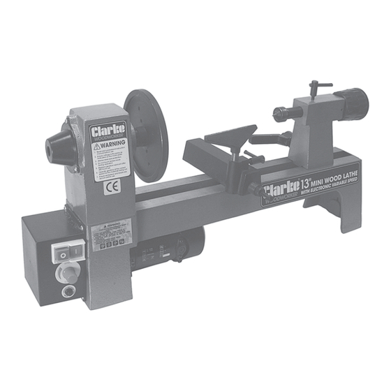
Page 7: Main Components
Tail-stock Spindle Tool Rest Locking Lever Tail-stock Body Tail-stock Advancing Handle ACCESSORIES The following range of accessories are also available from your Clarke dealer: 8-Piece Chisel Set Part No: 6500649 4-Jaw Independent Lathe Chuck Part No: 6500645 1/2” Cap. 1MT Tailstock Chuck Part No: 6500643 2”... -
Page 8: Unpacking & Assembly
UNPACKING When unpacking, check for damage or omissions etc. Any found should be reported to your CLARKE dealer where the appliance was originally purchased. Do not discard the packaging until the machine is assembled. The following items are supplied loose:... - Page 9 ASSEMBLY 1. Screw the tailstock spindle into the tailstock as shown in Fig 1. Note: A left-hand thread is used for this. 2. Attach the tailstock spindle locking lever and the tailstock locking lever in their postions using the coil spring and machine screw provided.
-
Page 10: Operation
OPERATION 1. Press the green push-button to start the lathe and adjsut the speed using the speed control knob. 2. Always use the lowest speed when starting a new workpiece. 3. Always rotate the workpiece by hand before turning on the motor and check it does not strike the tool/tool rest. -
Page 11: Technical Specification
TECHNICAL SPECIFICATION s l i & " 4 Please note that the details and specifications contained herein, are correct at the time of going to print. However, CLARKE International reserve the right to change specifications at any time without prior notice. -
Page 12: Troubleshooting
TROUBLESHOOTING l l i . r i , t i . t i f i l . y l l l i . r i . s r . t i s l i . t i & l l u z i s . -
Page 13: Parts List And Diagrams
PARTS DIAGRAM... - Page 14 PARTS LIST t - f s l i s l i s l i t f i When requesting spare parts, please quote the reference QBCWL325V followed by the number (1-49) on the above parts list.
-
Page 15: Declaration Of Conformity
DECLARATION OF CONFORMITY...
Need help?
Do you have a question about the WOODWORKER CWL325V and is the answer not in the manual?
Questions and answers