
Related Manuals for Clarke CWL1000B


Summary of Contents for Clarke CWL1000B
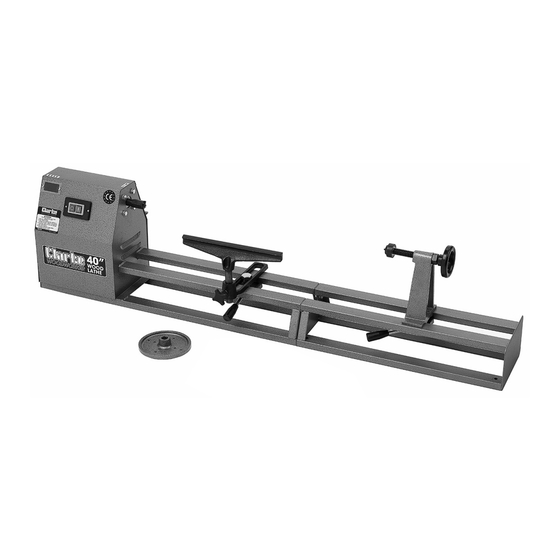
- Page 1 40” WOODLATHE MODEL NO: CWL1000B PART NO: 6500687 OPERATION & MAINTENANCE INSTRUCTIONS GC0817 - ISS 1 ORIGINAL INSTRUCTIONS...
- Page 2 GUARANTEE This CLARKE product is guaranteed against faulty manufacture for a period of 12 months from the date of purchase. Please keep your receipt as proof of purchase.
- Page 3 SAFETY WARNINGS CAUTION: FAILURE TO FOLLOW THESE PRECAUTIONS COULD RESULT IN PERSONAL INJURY, AND/OR DAMAGE TO PROPERTY. WORK ENVIRONMENT 1. Keep the work area clean and well lit. Cluttered and dark areas invite accidents. 2. Do not operate power tools in explosive atmospheres, such as in the presence of flammable liquids, gases or dust.
- Page 4 2. This lathe is designed for indoor environments and must not be used for other purposes. 3. If the lathe requires repair, always contact your Clarke dealer. Always insist on original spare parts. Repairs carried out by unauthorized persons may be dangerous and invalidate the guarantee.
- Page 5 2. Do not use the power tool if the switch does not turn it on and off. Any power tool that cannot be controlled with the switch is dangerous and must be repaired. 3. Disconnect the power tool from the power supply before making any adjustments, changing accessories, or storing the tool.
- Page 6 5. ALWAYS stop the lathe before removing workpieces, work supports or swarf from the table. 6. ALWAYS be sure that the workpiece is securely locked in position 7. ALWAYS keep hands and fingers away from the moving workpiece. SAFETY SYMBOLS The following safety symbols may be found on the machine.
- Page 7 ELECTRICAL CONNECTIONS WARNING: READ THESE ELECTRICAL SAFETY INSTRUCTIONS THOROUGHLY BEFORE CONNECTING THE PRODUCT TO THE MAINS SUPPLY. Before switching the product on, make sure that the voltage of your electricity supply is the same as that indicated on the rating plate. This product is designed to operate on 230VAC 50Hz.
-
Page 8: Table Of Contents
CONTENTS Check that all components are present and undamaged. Should any loss or damage be apparent, please contact your CLARKE dealer immediately. The following components are supplied loose with the lathe assembly. Item Description Item Description Tailstock spindle Drive centre... -
Page 9: Tailstock
MAIN COMPONENTS Item Description Item Description Headstock Tailstock advance handle On/Off switches Tailstock revolving centre Drive centre Toolrest Pulley viewing window Tailstock Faceplate Parts & Service: 020 8988 7400 / E-mail: Parts@clarkeinternational.com or Service@clarkeinternational.com... - Page 10 ASSEMBLY 1. Bolt the two halves of the bed together, using the four nuts, bolts and washers supplied. Make sure that the two halves are aligned so that the assembly lies flat on the work surface. 2. Place the tailstock on the bed and assemble the tail stock clamp assembly (8 in Fig 1) to the tail stock with the bolt through the...
- Page 11 5. Screw the tail shaft into the tailstock and screw on the locking nut. 6. Fit the handle to the flats on the end of the shaft and secure the handle by tightening the grub screw. 7. Assemble the tool support bracket to the machine as shown in Fig 6.
- Page 12 screwed to the headstock, the drive spindle being held using the spanner provided, to grip the flats on the spindle. 14. Your lathe is now fully assembled and ready for use. SPINDLE SPEEDS The position of the drive belt on the pulleys is visible through the viewing window and marked on the top of the lathe as shown below.
- Page 13 FACEPLATE TURNING SQUARE LENGTH ROUGHING FINISHING 1” (25mm) 12” (305mm) 1750 2550 2” (50mm) 16” (406mm 1240 2550 3” (75mm) 20” (508mm) 2550 4” (100mm) 20” (508mm) 2550 Fig 9 shows the belt positioned on the second step from the outside face of the pulley.
- Page 14 OPERATION 1. Make sure that the tool rest and tailstock are securely locked in position before starting work. 2. Always rotate the workpiece by hand before turning on the motor and check it does not strike the tool/tool rest. 3. Always use the lowest speed when starting a new workpiece and roughly turn the work to a round shape at low speed.
- Page 15 • The motor will not run if the cover is not secured. Please refer to TROUBLESHOOTING on page 16. If you are unable to rectify any faults, please contact your local dealer or Clarke International Service Department on 0208 988 7400 for assistance. OPTIONAL ACCESSORIES The following are available from your local Clarke supplier.
- Page 16 Then turn the lathe back on Send to your Clarke dealer for repair. 2. Defective/broken switch. 2. Send to your Clarke dealer Damaged power cable. for replacement. Motor will not start 1. Short circuit in motor or 1.
- Page 17 DECLARATION OF CONFORMITY Parts & Service: 020 8988 7400 / E-mail: Parts@clarkeinternational.com or Service@clarkeinternational.com...
- Page 18 PARTS DIAGRAM Parts & Service: 020 8988 7400 / E-mail: Parts@clarkeinternational.com or Service@clarkeinternational.com...
-
Page 19: Bed Extension
PARTS LIST PART NO DESCRIPTION PART NO DESCRIPTION Power Cable Headstock Frame Ball Bearing Bearing Block Bearing Block Lock Washer Ball Bearing Washers Washer Spring Washer Bolt Wire clip Headstock Spindle Screw Centre Spur Upper Belt Pulley Tool Post Support Lower Belt Pulley Locking Bolt End Cap...
Need help?
Do you have a question about the CWL1000B and is the answer not in the manual?
Questions and answers