
Related Manuals for Clarke Woodworker CWL1000


Summary of Contents for Clarke Woodworker CWL1000
- Page 1 40” WOODLATHE 40” WOODLATHE Model No. CWL1000 Part No. 6500685 OPERATING & MAINTENANCE INSTRUCTIONS 0408...
-
Page 2: Table Of Contents
DECARATION OF CONFORMITY We declare that this product conforms to the followinhg EC Directive: • 98/37/EC signed D. Kemp Engineering Manager CONTENTS Page Lathe Specifications ....................3 General Safety Instructions ..................4 Wood Lathe Safety Instructions ................. 5 Electrical Connections and Motor Specifications ........... 6 Unpacking And Checking Contents ................ -
Page 3: Lathe Specifications
GUARANTEE This CLARKE product is guaranteed against faulty manufacture for a period of 12 months from the date of purchase. Please keep your receipt as it will be required as proof of purchase. This guarantee is invalid if the product is found to have been abused or tampered with in any way, or not used for the purpose for which it was intended. -
Page 4: General Safety Instructions
GENERAL SAFETY RULES FOR OPERATING MACHINERY WARNING As with all machinery, there are certain hazards involved with their operation and use. Exercising respect and caution will considerably lessen the risk of personal injury. However, if normal safety precautions are overlooked, or ignored, personal injury to the operator may result. 12. -
Page 5: Wood Lathe Safety Instructions
ADDITIONAL SAFETY RULES FOR WOOD LATHES IMPORTANT: You should not operate this 10. When using the Faceplate, ensure the workpiece is securely fastened to it and machine unless you are thoroughly familiar with wood turning lathes and wood turning the appropriate size faceplate is used to techniques. -
Page 6: Electrical Connections And Motor Specifications
ELECTRICAL CONNECTIONS Connect the mains lead to a standard 230 volt (50Hz) electrical supply using a 13 amp BS1363 plug fitted with a 13 amp fuse. or a suitably fused isolator switch. WARNING : THIS APPLIANCE MUST BE EARTHED. IMPORTANT : The wires in the mains lead are coloured in accordance with the following code : Green &... -
Page 7: Unpacking And Checking Contents
Please check the carton contents carefully, if any parts are missing or damaged in any way, contact your Clarke dealer immediately. Ensure the lathe is secured firmly to a firm level surface...a sturdy workbench for example, or, if necessary, a piece of 1/2”... -
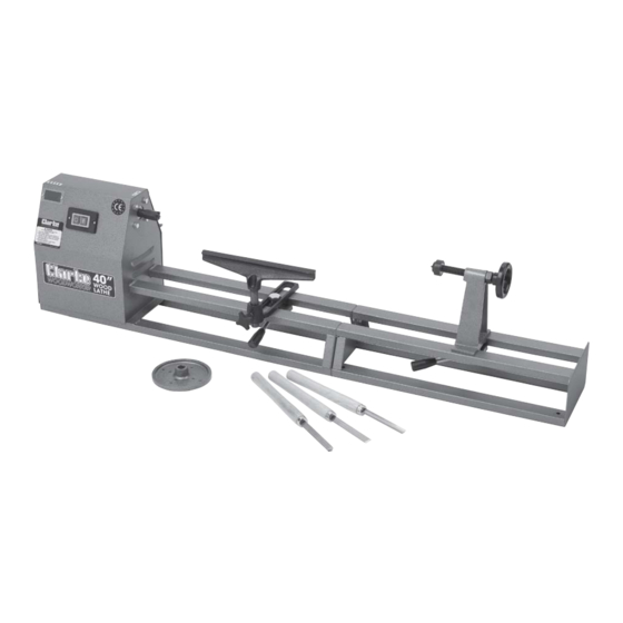
Page 8: Main Component Id
MAIN COMPONENTS Fig.2 Headstock Tailstock Revolving Centre ON/OFF switches Tool Rest Drive Centre Pulley Observation Window Faceplate Tailstock 3-Piece Chisel Set Tailstock Advancing Handle ASSEMBL Y Bolt the two halves of Fig.3 the bed together, using the four nuts, bolts and washers supplied, ensuring the two halves are perfectly aligned... - Page 9 Fig.5 3. Screw in the Tailstock threaded shaft, screw on the locking nut, and attach the Handle to the flats on thre end of the shaft. Secure the Handle by tightening the grub screw. 4. Disassemble the Tool Support Bracket, and Fig.6 reassemble to the machine in the manner shown in Fig.6.
-
Page 10: Spindle Speeds And Belt Tensioning
SPINDLE SPEEDS A chart showing spindle speeds and recommended turning speeds is mounted on the Head cowl and for convenience, is duplicated as follows: SPINDLE SPEEDS RECOMMENDED GENERAL SPEEDS SPINDLE TURNING SQUARE LENGTH ROUGHING FINISHING 1” (25mm) 12” (305mm) 1750 2510 2”... -
Page 11: Basic Techniques
BASIC WOOD TURNING TECHNIQUES 1. SPINDLE TURNING 1.8 Place the wood between the centres and If you are not experienced at the art of wood advance the tailstock so that the rotating turning, we suggest that you practice using the centre is forced into the spindle at the exact various wood turning tools, starting with turning centre mark, rotating the spindle as you do... - Page 12 2. FACEPLATE TURNING All face plate work is done by scraping. Any Tur ning which cannot be worked through attempt to use a cutting technique on edge centres, must be mounted on a faceplate, or grain, will result in hogging or gouging, which other work-holding device.
-
Page 13: Using Woodworking Chisels
Fig. 12 An 8 piece chisel set is available from your CLARKE dealer, part no. 6500649 2. THEORY OF TURNING There are two classes of chisel; these are : a . Chisels intended primarily for cutting, and b . - Page 14 Either a cutting or scraping action can be used chisel, then when cutting at the circumference. The shaving improperly suppor ted is removed like a peeling from a potato. chisel will begin bounce, chatter, Scraping only, is used when cutting at the against the workpiece.
- Page 15 2.4 How to Position Tool Rest for 3.USING THE GOUGE Circumference Scraping Fig. 14 In scraping operations, the tool rest position is not as critical as it is for cutting operations. The chisel generally is held horizontally, though it can be held at an angle to reach into tight places.
- Page 16 bevel side down, keep the base of the bevel scraping, when cutting methods cannot be against the work. Good practice is to place employed. the skew well over the work, pull it back until The spear point is used for fine scraping and the edge begins to cut, then swing the handle delicate operations, such as the for ming of into position to advance the cut.
- Page 17 9. USING WOOD RASPS AND FILES 10.2 Finish Cutting Fig. 20 Fig. 22 Finish cutting requires more control with less force and is better done with the palm of the A wood rasp will remove stock quickly when tool rest hand turned up. The wrist is still held held against the revolving workpiece.
-
Page 18: Making Standard Cuts
MAKING STANDARD CUTS 1. THE ROUGHING OFF-CUT as desired at any spot along the work. At this stage long cuts from the centre of either Reducing a square or odd shaped workpiece end can also be taken. Roughing-off generally down to a cylinder of approximate size for finish is continued until the cylinder is approximately turning is called roughing-off. - Page 19 heel of the skew into it along the surface of the 5. CUTTING A SHOULDER outside area. Tilt the cutting edge with handle raised up, so A shoulder can be the side of a square portion that only the extreme heel does this cutting. If left in the workpiece, the side of a turned section the shoulder is at the end of work, the process is or the end of the workpiece.
- Page 20 Now draw the skew straight back whilst raising Fig. 33 the handle slowly, until the edge of the heel at the pencil line starts to cut. As the edge begins to cut, roll the skew in the direction of the vee, so that the exact portion of the edge, when started cutting, will travel in a 90°...
-
Page 21: Spindle Turnings
SPINDLE TURNINGS 1. PLOTTING THE SHAPE 2. DUPLICATE TURNINGS Once the basic cuts have been mastered, you Identical turnings require great accuracy when are ready to turn out finished work. plotting the work and doing the various cuts. Many methods have been devised to assist in The first step is to prepare a plan for the perfecting the work. - Page 22 turning. The first finished turning can also be Position the backstick against a pre-tur ned used as a template. por tion near the centre of the spindle, this Attach the template to a board, then mount portion being at least 3mm over finish size to the board behind the lathe on hinges, so that allow for later removal of any marks made upon the template can be moved down to touch the...
-
Page 23: Face Plate And Chuck Turnings
FACEPLATE & CHUCK TURNINGS 3. DEEP RECESSES Fig. 40 Remove the bulk of the waste (to rough-out the desired recess), by scraping with the round-nose chisel or the gouge. Remove up to within 1/8” of finished size in this manner. Finish off the inside circumference by scraping with the spear point chisel or skew. -
Page 24: Fancy Face Plate Turnings
FANCY FACE PLATE TURNINGS Fig. 43 After making a recess at least 1/2 the way through the workpiece, and finishing this on the inside, remove the workpiece from the lathe. Now mount a short length of soft wood stock on the screw centre and turn this down to form a dowel that will be a tight press (not driving) fit inside the recessed end of the cylinder. - Page 25 and mounted on this chuck. thus mounted, the After being chucked the remaining face of the remaining contours can be turned to shape. ring can be turned to the proper contour, thus cutting away the centre portion. Fig. 47 Work of this type take constant measurements, or better still, use a template to guard against over or under cutting.
- Page 26 the ball is constantly shifted, never more than Fig. 51 1/8 turn and always with a definite pattern. Since turning between centres makes the work a perfect sphere across the grain, the ball must be mounted in the chuck so that the first scraping cuts will round it up in the opposite direction .
-
Page 27: Turning Plastics
TURNING PLASTICS 1. TYPES OF PLASTICS 4. USE OF FORMED TOOLS FOR PRODUCTION BEADING AND There are two general groups of plastics. The SIMILAR OPERATIONS first includes all phenol plastics moulded under heat and pressure. Bakelite and Formica are Fig.54 examples. -
Page 28: Sanding, Buffin8G And Polishing
SANDING, BUFFING AND POLISHING Fig. 56 The application of the sandpaper strip is shown in fig. 57. Care must be exercised in order to prevent dubbing the corners of beads, shoulders etc. It is good practice to finish sanding with the work in reverse rotation. -
Page 29: Maintenance
Periodically lubricate the the tailstock screw threads with either SAE20 or SAE30 engine oil. SPARE PARTS AND SERVICING For spare parts or servicing, please contact your nearest Clarke dealer or Clarke International on one of the following numbers. PARTS & SERVICE TEL: 020 8988 7400 e-mail as follows: PARTS: Parts@clarkeinternational.com... -
Page 30: Spares And Servicing Contacts
1 RWL1000IA0001A 69 Circlip 1 GB894186 SPARE PARTS AND SERVICING For spare parts or servicing, please contact your nearest Clarke dealer or Clarke International on one of the following numbers. PARTS & SERVICE TEL: 020 8988 7400 e-mail as follows: PARTS: Parts@clarkeinternational.com... -
Page 31: Parts Diagram
PARTS DIAGRAM...
Need help?
Do you have a question about the Woodworker CWL1000 and is the answer not in the manual?
Questions and answers