
Related Manuals for Clarke Metalworker CL430


Summary of Contents for Clarke Metalworker CL430
- Page 1 METAL LATHE - CL430 & LATHE/MILL DRILL - CL500M OPERATING & MAINTENANCE INSTRUCTIONS 1105...
- Page 2 DISCLAIMER This manual is intended to instruct the user on the operations peculiar to the CL430 Lathe and CL500M Lathe/Mill Drill ONLY. Although some reference is made, and advice given, regarding various metal turning techniques, it should not be regarded as a general tutorial on the subject.
-
Page 3: Guarantee
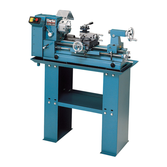
The flat lathe bed is solidly constructed from cast iron giving it exceptional rigidity and stability, making it an ideal tool for general turning operations. A complete range of accessories is available from your Clarke dealer, such as a Floor Stand with Drip Tray, Four Jaw Chuck, Steadies etc. Please see ‘Accessories’... -
Page 4: Table Of Contents
TABLE OF CONTENTS PAGE Guarantee .................... 3 Specifications ..................5 General Safety Precautions ............... 5 Additional Safety Rules for Metal Lathes .......... 7 Unpacking and Installation ..............8 Mounting the Mill Head ........... 10 List/ Description of Loose Parts ........ 12 Electrical Connections .............. -
Page 5: Specifications
CL430 Part No............7610800 CL500M Part No........... 7610300 Please note that the details and specifications contained herein, are correct at the time of going to print. However, CLARKE International reserve the right to change specifications at any time without prior notice. -
Page 6: General Safety Precautions
GENERAL SAFETY PRECAUTIONS FOR OPERATING MACHINERY CAUTION As with all machinery, there are certain hazards involved with their operation and use. Exercising respect and caution will considerably lessen the risk of personal injury. However, if normal safety precautions are overlooked or ignored, personal injury to the operator or damage to machinery may result. -
Page 7: Additional Safety Rules For Metal Lathes
18. DO NOT STAND ON THE MACHINE. Serious injury could occur if the machine is tipped over. Do not store materials above or near the machine such that it is necessary to stand on the machine to get to them. 19. -
Page 8: Unpacking And Installation
Fig.1, shows model CL500M. Model CL430 is similar, but does not include the Mill Head - shown at ‘A’. CL430 users should therefore ignore all reference to the Mill Head . Inspect to ensure that no damage was suffered during transit. Should any damage be apparent, please contact your Clarke dealer immediately. - Page 9 An optional floor stand complete with drip tray, specially designed for this product, is available from your CLARKE dealer. Bolt the lathe to the stand ensuring bolts are fully tightened. If the stand is not used, then the lathe should be mounted on a strong, heavy workbench, of sufficient height so that you do not need to bend your back to perform normal operations.
-
Page 10: Mounting The Mill Head
• Fit the Chuck Guard according to Fig.5. Fig.5 CL500M: Remove the transit screw in the base of the Mill Head from the position arrowed at ‘B’, (if fitted). Secure the Stop Bar ‘A’ with the screw and flat washer ‘B’ found in the guard kit. The screw attached to the Guard - ’C’... - Page 11 Fig.8 • Slide the Arbor into the spindle and push home - fully (Fig.8)..Fig.9 ..then screw the Draw Bar (‘A’Fig.9), down through the spindle and into the arbor - fully. Secure by tightening the locknut (‘B’ Fig.9). • The chuck may now be located on the morse tapered arbor. Tap home using a block of wood ONLY.
-
Page 12: List/ Description Of Loose Parts
• Fit the Chuck Guard as follows: Fig.11 a. Unscrew and remove the spindle sleeve locating peg from the front of the mill head shown at ‘H’, Fig. 10. b. Screw the Guard Support assembly (‘A’ Fig. 11) - to be found in the box of loose parts, into the hole vacated by the locating peg, until it binds. -
Page 13: Electrical Connections
ELECTRICAL CONNECTIONS CAUTION! DO NOT ATTEMPT TO USE THE MACHINE UNTIL INSTALLATION IS COMPLETED, AND ALL PRELIMINARY CHECKS HAVE BEEN MADE IN ACCORDANCE WITH THIS MANUAL. Connect the mains lead to a standard, 230 Volt (50Hz) electrical supply through an approved 13 amp BS 1363 plug, or a suitably fused isolator switch. -
Page 14: Features
FEATURES Fig.13 Mill Head Compound Slide Feed Handle Mill Head Locking Lever Cross Slide Mill Head Elevating Lever Saddle Mill Head Elevating Collar Cross Slide Feed Handle Pulley Cover securing Knob Leadscrew Spindle Cover (2-part) Leadscrew Locking Lever Spindle Micro Feed Knob Saddle Feed Handle. -
Page 15: The Headstock
Morse Taper for use with the Centre provided, A Revolving Centre and Drill Chuck are also available from your Clarke dealer. (See Accessories on page 26). It is also possible to remove the Tailstock completely, which may be necessary for milling large pieces. -
Page 16: The Mill Head
Cross Slide, for milling purposes, using the ‘T’ slots provided. A 12 piece T-nut and bolt set is available from your CLARKE dealer. Alternatively, a Vice (supplied) may be bolted to the Cross Slide, using the T-slots, in order to secure a workpiece. -
Page 17: Preparation For Use
PREPARATION FOR USE A. SIMPLE TURNING The following notes are guidelines as to how to set up the lathe in order to carry out a simple turning operation. ALWAYS plan your work. Have drawings or a plan on hand together with any measuring instruments you may require, such as micrometers/verniers/callipers etc. - Page 18 2. Mount the Cutting Tool Select a cutting tool that will produce the desired cut and mount it in the Tool Rest, with as little overhang as possible, securing it using three hex socket head screws. (Ideally, the overhang should be approx. 10 mm but not more than 15mm for a straight tool).
-
Page 19: Using Power Feed
B. SIMPLE TURNING WITH POWER FEED The same basic setup is used as for simple turning, except that, before starting, the 2-Speed Lever is set to either 1 or 2 in order to provide the desired feed rate. CAUTION: NEVER attempt to change speeds whilst the machine is operating. As mentioned previously, the rotational speed of the leadscrew, and hence the rate of feed of the tool, is dependant upon the gear train configuration. -
Page 20: Screw Cutting
The taper, or bevel, is cut by setting the cross Fig.19 slide appropriately then using the compound slide feed handle to advance the cutting tool in the direction of the arrow as shown in Fig.18. D. SCREW CUTTING This operation requires a degree of skill and accuracy, and should not be attempted unless you are completely familiar with all aspects of the lathe. -
Page 21: Changing Gears For Screw Cutting
CHANGING GEARS FOR SCREW CUTTING The leadscrew is driven via a gear train, The gear ratio will therefore determine the rotational speed of the leadscrew with relation to the spindle. i.e. one turn of the spindle will turn the leadscrew an amount determined by the gear ratio. By setting the gears to a known ratio, we can therefore produce threads to a known size. - Page 22 NOTE: Fig. 21 shows a gear configuration for simple turning. A - 30 B - 60 C - 27 D - 63 To cut 12 TPI, Imperial Thread, use 60T at position A, 36T at position B 50T at position C 27T at position D In order to change the gears, ensure the machine is switched OFF and disconnected from the mains supply.
-
Page 23: Maintenance
MAINTENANCE For maximum performance, it is essential that the lathe is properly maintained. BEFORE USE Always inspect before use. Any damage should be repaired and maladjustments rectified. Damage to machined surfaces should be repaired with an oil stone. Test by hand to ensure smooth operation of all parts before use. Inject a few drops of oil to the oilways 1 - 8 Fig. -
Page 24: Settings And Adjustments
SETTINGS AND ADJUSTMENTS Occasionally, it may be necessary to readjust various components in order to maintain optimum performance. The adjustments that may be performed are as follows: A. Compound Slide Adjustments The cross-slide is mounted on a dovetail slide, as shown in Fig. 23. Between the sloping surfaces on one side of the dovetail, a ‘jib strip’... -
Page 25: 3-Jaw Chuck - External Jaws
C. Cross-slide Adjustments Cross slide adjustments are made in the same way as those for the compound slide. The jib screws however are hex socket head screws and are to be found on the right hand side of the slide, i.e. facing the tailstock. NOTE: It is important that the cross-slide and compound slide adjustments are correctly carried out and that there is no ‘sloppiness’... -
Page 26: Accessories
ACCESSORIES A range of accessories is available from your Clarke dealer which extends the versatility of your machine. These are as follows: Machine Block Part No: 7610324 Bolted to the Cross-Slide Moving Steady Fixed Steady Part No: 7610318 Part No: 7610317... - Page 27 Independent 4-Jaw Chuck with Adapter Plate. Part No. 7610316 ..............Tailstock Revolving Centre Part No. 7610320 ..........Tailstock Drilling Chuck - MT3. Part No. 7610330 ................6 Piece Cutting Tool Set. Comprising tools for 60 thread cutting, parting/grooving, facing and general turning work.
Need help?
Do you have a question about the Metalworker CL430 and is the answer not in the manual?
Questions and answers