
Related Manuals for Clarke Metalworker CL250M


Summary of Contents for Clarke Metalworker CL250M
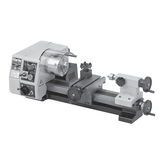
- Page 1 250mm (10 inch) 250mm (10 inch) VARIABLE SPEED METAL LATHE VARIABLE SPEED METAL LATHE Model No. CL250M Part No. 7610740 OPERATING & MAINTENANCE INSTRUCTIONS © 1203...
-
Page 2: Specifications
SPECIFICATIONS Motor ..............230VAC, 50Hz, 1 Phase Power Rating ..........150Watts Current Rating ..........5Amps Distance Between Dead Centres ...... 250mm (10”) Centre Height ............70mm Max. Work Diameter ..........140mm Spindle Bore ............9mm Spindle Taper ............No.2 Morse Taper Tailstock Taper ............ -
Page 3: Table Of Contents
Settings and Adjustments ..............17 Accessories ..................18 Parts Diagram ..................19 Parts List ....................20 Wiring Diagram .................. 22 Spare Parts & Service Contacts ............22 Personal Notes ................... 23 © Copyright, CLARKE International. August 2003. All rights reserved... -
Page 4: Guarantee
The Machine is capable of turning up to a maximum diameter of 140mm and an overall length of 250mm. A full range of accessories is available from your Clarke dealer, so that the machine is capable of Milling, producing short tapers, and metric threads, both left and right hand. -
Page 5: General Safety Precautions
GENERAL SAFETY PRECAUTIONS FOR OPERATING MACHINERY As with all machinery, there are certain hazards involved with their operation and use. Exercising respect and caution will considerably lessen the risk of personal injury. However, if normal safety precautions are overlooked or ignored, personal injury to the operator or damage to machinery may result. -
Page 6: Additional Safety Rules For Metal Lathes
18. DO NOT STAND ON THE MACHINE. Serious injury could occur if the machine is tipped over. Do not store materials above or near the machine such that it is necessary to stand on the machine to get to them. 19. -
Page 7: Features
FEATURES FIG.1 THE HEADSTOCK The motor drives the Spindle via an internal tooth type belt. Spindle speed is variable, and is regulated by the Speed Control Knob. The spindle, is provided with an internal No.2 Morse taper to accommodate a centre for use with a drive dog assembly when turning between centres.(See ‘Accessories’) The Chuck Guard, is an essential component and must always be lowered into place when using the lathe. -
Page 8: The Tailstock
A Metric thread cutting kit, comprising a number of gear wheels, is available from your Clarke dealer (see Accessories). A chart, on the headstock, indicates the gear configuration for various thread sizes. The procedure for changing the gears is given in the literature accompanying the Thread Cutting Kit. -
Page 9: Unpacking And Preparing For Use
On receipt, carefully unpack the lathe. Inspect to ensure that no damage was suffered in transit and all parts are accounted for. Should any damage be apparent, or parts are missing, please contact your Clarke dealer immediately. FIG.2 The following loose items are to be found in the packing case...Item numbers are those shown in the parts list on page 21 900. -
Page 10: Installation - Electrical Connections
INSTALLATION CAUTION! DO NOT ATTEMPT TO USE THE MACHINE UNTIL INSTALLATION IS COMPLETED, AND ALL PRELIMINARY CHECKS HAVE BEEN MADE IN ACCORDANCE WITH THIS MANUAL. ELECTRICAL CONNECTIONS Connect the mains lead to a standard, 230 Volt (50Hz) electrical supply through an approved 13 amp BS 1363 plug, or a suitably fused isolator switch. -
Page 11: Mounting The Lathe
B. MOUNTING THE LATHE The lathe should be mounted on a strong, heavy workbench, of sufficient height so that you do not need to bend your back to perform normal operations. Take the necessary precautions when moving the lathe considering its’ weight. Assistance will be required. - Page 12 a. Turn the ‘Emergency Stop so that it springs out. b. Turn the ‘Forward/OFF/Reverse’ switch to Forward or Reverse. c. Turn the ‘Power Drive’ control knob, which drives the Leadscrew, to the ‘HAND’ position..NO Drive. IMPORTANT: This should ALWAYS be a deliberate,conscious action. d.
-
Page 13: Operation - Simple Turning
Additionally, ‘Steadies’ may be used which are available from your Clarke Dealer. If the Tailstock is not to be used, move it out of the way by slackening the two securing screws, sliding it to the end of the bed then nipping up the two screws. - Page 14 To check to ensure the tip is at the correct height, position the tool so that the tip is almost touching the point of the tailstock centre. They should coincide. If necessary make adjustments using shims, grind down the FIG.6 cutting tool tip or select another tool.
-
Page 15: Using Power Feed
The rotational speed of the leadscrew, and hence the rate of feed of the tool, is dependant upon the gear configuration of the gear train. This is factory set for general turning operations. Kits are available from your CLARKE dealer for screw cutting. -
Page 16: Maintenance
5. Retract the tool one or two complete turns on the cross-slide feed, then wind the saddle so that the tool is at the start point once again. Advance the tool the same number of turns, plus the depth of cut, and when ready, turn the Power Drive Control knob clockwise to engage the clutch again and procede to take another cut. -
Page 17: Settings And Adjustments
SETTINGS AND ADJUSTMENTS Occasionally, it may be necessary to readjust various components in order to maintain optimum performance. The adjustments that may be performed are as follows: A. CROSS-SLIDE AND SADDLE ADJUSTMENTS The Cross-Slide and Saddle are mounted on dovetail slides,illustrated in FIG. 10. Between the sloping surfaces on one side of the dovetail, a ‘jib strip’... -
Page 18: Accessories
ACCESSORIES A range of accessories is available from your Clarke dealer which extends the versatility of your machine. A sample of these is as follows: P/No. 7610721 1. Independant 4-Jaw Chuck 80mm dia..........P/No. 7610742 2. Face Plate - 115mm dia........ -
Page 19: Parts Diagram
SPARE PARTS DIAGRAM... -
Page 20: Parts List
SPARE PARTS LIST No: Description Qty Part No: No: Description Qty Part No: Key 6*36 SG250M040 Running Gear Cover SG250M001 Spindle SG250M041 Cap Screw M4*8 SG250M002 SG250M042 Cap Screw M4*12 SG250M003 Nut M6 SG250M043 Hinge SG250M004 Washer SG250M005 Screw M6*25 SG250M044 Nut M4 SG250M006... - Page 21 Cont: No: Description Qty Part No: No: Description Qty Part No: Washer SG250M080 119 PC Board Box SG250M119 Change Gear Z=72 SG250M081 120 Screw SG250M120 Change Gear Z=19 SG250M082 121 Micro Switch SG250M121 Change Gear Z=76 SG250M083 122 Screw SG250M122 Change Gear Z=24 SG250M084 123 Power Cord With Plug...
-
Page 22: Wiring Diagram
WIRING DIAGRAM SPARE PARTS & SERVICE For Spare Parts and Service, please contact your nearest dealer, or CLARKE International, on one of the following numbers. PARTS & SERVICE TEL: 020 8988 7400 PARTS & SERVICE FAX: 020 8558 3622 e-mail as follows: PARTS: Parts@clarkeinternational.com...
Need help?
Do you have a question about the Metalworker CL250M and is the answer not in the manual?
Questions and answers