
Related Manuals for Clarke MetalWorker CL300M


Summary of Contents for Clarke MetalWorker CL300M
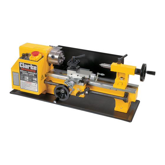
- Page 1 300mm VARIABLE SPEED METAL LATHE Model No. CL300M OPERATING & MAINTENANCE INSTRUCTIONS 1008...
-
Page 2: Specifications
PARTS & SERVICE - 020 8988 7400 e-Mail: Parts@clarkeinternational.com or Service@clarkeinternational.com Please note that the details and specifications contained herein, are correct at the time of going to print. However, CLARKE International reserve the right to change specifications at any time without prior notice. -
Page 3: Table Of Contents
TABLE OF CONTENTS PAGE Specifications ..................2 Spare Parts & Service ................2 Guarantee .................... 5 General Safety Precautions .............. 6 Additional Safety Rules for Metal Lathes .......... 7 Features ....................8 The Headstock ............9 The Running Gear ............9 The Tailstock .............. -
Page 5: Guarantee
300mm. It is further capable of producing short tapers and Imperial threads, both left and right hand. Metric threads may also be cut with the addition of a Metric Conversion Kit, available from your Clarke dealer (see ‘Accessories’ for details). -
Page 6: General Safety Precautions
GENERAL SAFETY PRECAUTIONS FOR OPERATING MACHINERY CAUTION As with all machinery, there are certain hazards involved with their operation and use. Exercising respect and caution will considerably lessen the risk of personal injury. However, if normal safety precautions are overlooked or ignored, personal injury to the operator or damage to machinery may result. -
Page 7: Additional Safety Rules For Metal Lathes
18. DO NOT STAND ON THE MACHINE. Serious injury could occur if the machine is tipped over. Do not store materials above or near the machine such that it is necessary to stand on the machine to get to them. 19. -
Page 8: Features
FEATURES 23 24 Fig. 1 LEGEND Rear view of headstock 1. Headstock 15. Automatic Feed Lever 2. Spindle Flange 16. Cross-Slide Feed Handle 3. Chuck Guard 17. Apron 4. 3- Jaw Chuck 18. Manual (Saddle) Feed Handle 5. Tool Post 19. -
Page 9: The Headstock
(10), at its base. The Tailstock Spindle carries an internal No.2 Morse taper for use with the Centre (8) provided. A Revolving Centre and Drill Chuck are also available from your Clarke dealer. (See Accessories on page23). -
Page 10: The Saddle
THE MOTOR It is not recommended that you dis-assemble the motor. Brushes may be replaced as described under ‘Maintenance’. For all other servicing and repairs, please contact your Clarke dealer. OVERLOAD INDICATOR The overload indicator will light up when excessive strain is placed on the motor. -
Page 11: Unpacking And Preparing For Use
On receipt, carefully unpack the lathe. Inspect to ensure that no damage was suffered in transit and all parts are accounted for. Should any damage be apparent, or parts are missing, please contact your Clarke dealer immediately. The following loose items are to be found in the packing case. -
Page 12: Installation - Electrical Connections
INSTALLATION CAUTION! DO NOT ATTEMPT TO USE THE MACHINE UNTIL INSTALLATION IS COMPLETED, AND ALL PRELIMINARY CHECKS HAVE BEEN MADE IN ACCORDANCE WITH THIS MANUAL. ELECTRICAL CONNECTIONS Connect the mains lead to a standard, 230 Volt (50Hz) electrical supply through an approved 13 amp BS 1363 plug, or a suitably fused isolator switch. -
Page 13: Starting Procedure
We strongly recommend that the machine is bolted firmly to a strong workbench using the tapped holes used to secure the feet to the lathe. This is to provide added stability and consequently, additional safety. To do this, remove the four M6 screws which secure the rubber feet and chip tray to the machine (if already fitted) and discard the feet. - Page 14 Check that all components are still secure and working freely and correctly. Check also to ensure the mountings are secure. Repeat the procedure at the HIGH range setting Should any adjustments be necessary, refer to the appropriate section under Settings and Adjustments. NOTE: When changing from HIGH to LOW range, it may be necessary to turn the spindle by hand, in order for the gears to mesh correctly.
-
Page 15: Operation - Simple Turning
OPERATION A. SIMPLE TURNING Before starting the machine, as described above, it is imperative that the setup for the type of work to be carried out is fully checked. Fig 6 The following notes are guidelines as to how to set up the lathe in order to carry out a simple turning operation. - Page 16 It may be necessary to adjust the position of the compound slide or reposition the work in the chuck to guarantee that there is adequate clearance. Fig 7 When satisfied retract the cutting tool and wind the saddle away from the headstock, then wind the cutting tool up to the work, somewhere along the length to be cut, whilst rotating the...
-
Page 17: Using Power Feed
B. SIMPLE TURNING WITH POWER FEED The same basic setup is used as described above, except that, before starting, the Leadscrew F/N/R Lever (25) is set to the ‘Forward’ position and the Auto Feed Lever (15), is operated in order to drive the saddle. As mentioned previously, the rotational speed of the leadscrew, and hence the rate of feed of the tool, is dependant upon the gear configuration of the gear train. -
Page 18: Bevel Cutting
For detailed information regarding screwcutting techniques, cutting tools etc., you should consult a suitable handbook or obtain advice from a qualified person. A leadscrew, with corresponding half nuts and thread dial indicator, for the production of Metric threads is available from your Clarke dealer, see ‘Accessories’ on page 24. - Page 19 The general procedure for screwcutting is as follows: 1. Try to get as much distance from the chuck to the end of the proposed screw thread as possible, and if your design allows, cut a ‘run-off’ into the work which is of a smaller diameter than the root diameter of the proposed screw thread.
-
Page 20: Changing Gears For Screwcutting
Threads Per Inch (TPI). A leadscrew for Metric thread cutting, complete with half nuts is available from your Clarke dealer. As previously mentioned, the actual thread produced will be totally dependant upon the profile of the cutting tool. It is not within the scope of this manual to provide detailed information regarding types of cutting tool, cutting speeds and working with various types of material etc., and it is strongly advised that you consult... -
Page 21: Gear Charts For Screw Cutting
GEAR CHART FOR CUTTING IMPERIAL THREADS INDICATOR TABLE Threads Gear Per Inch SCALE 1,3,5,7 1,3,5,7 1,3,5,7 1,3,5,7 1,3,5,7 1,3,5,7 1~8 indicates that any of the 8 lines may be used. Examples: 1. Ref. Fig A on page 19. To cut 12 TPI, use 40T in position A, 30T in position D, use the 65 tooth gear in position B to connect A and D. - Page 22 In order to change the gears, ensure the machine is switched OFF and disconnected from the mains supply. Remove the gear train cover which is secured with two hex. socket head screws. Gear A may be considered as the Driver, and Gear D as the Driven gear. When a Simple gear train is configured, as illustrated in Fig.
-
Page 23: Maintenance
MAINTENANCE For maximum performance, it is essential that the lathe is properly maintained. BEFORE USE Always inspect before use. Any damage should be repaired and maladjustments rectified. Damage to machined surfaces should be repaired with an oil stone. Test by hand to ensure smooth operation of all parts before use. Inject a few drops of oil to the oilways at both leadscrew bearings (each end bracket) and once or twice during the day if used continuously. - Page 24 To adjust the jib strip, to account for wear and ensure the slide moves evenly and smoothly, proceed as follows: 1. Slacken off all lock nuts and screw Fig. 13 inthe jib screws evenly, i.e. use the same torque for each screw. The slide should be held firmly.
-
Page 25: Accessories
ACCESSORIES A range of accessories is available from your Clarke dealer which extends the versatility of your machine. These are as follows: 1. Independant 4-Jaw Chuck 80mm dia....Part No. . 7610721 2. Face Plate - 160mm dia.............. 7610723 3. - Page 26 EXTERNAL JAWS - 3-Jaw Chuck To change the jaws, insert the chuck key and open the jaws to their fullest extent. It will then be possible to remove each jaw in turn. Fig.14 Replace them with the external jaws, noting the following.
-
Page 27: Parts List
PARTS LIST No. Description Part No. No. Description Qty Part No. 1 Bed Way HT300M001 41 Pinion 20T HT300M041 2 Chuck HT300M002 42 Fixed Cover HT300M042 3 Spindle HT300M003 43 Screw M6x20 HT300M043 4 Screw M6x30 HT300M004 44 Screw M5x10 HT300M044 5 Washer M6 HT300M005... - Page 28 Cont. No. Description Qty Part No. No. Description Qty Part No. 83 Screw M6x12 HT300M083 128 Key M3x16 HT300M128 84 Wheel HT300M084 129 Lead Screw Imperial 1 HT300M129 85 Knob HT300M085 131 Bracket HT300M131 86 Handle HT300M086 132 Plastic Plug HT300M132 87 Dial HT300M087...
-
Page 29: Parts Diagram
PARTS DIAGRAM... -
Page 30: Wiring Diagram
WIRING DIAGRAM... -
Page 31: Personal Notes
NOTES...
Need help?
Do you have a question about the MetalWorker CL300M and is the answer not in the manual?
Questions and answers