
Related Manuals for Clarke CWL460


Summary of Contents for Clarke CWL460
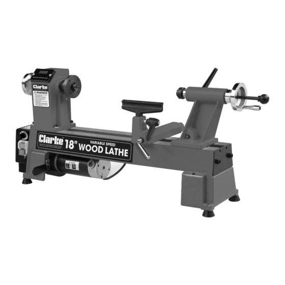
- Page 1 18” VARIABLE SPEED WOOD LATHE MODEL NO: CWL460 PART NO: 6501661 OPERATION & MAINTENANCE INSTRUCTIONS ORIGINAL INSTRUCTIONS GC0621...
-
Page 2: Specifications
GUARANTEE This CLARKE product is guaranteed against faulty manufacture for a period of 12 months from the date of purchase. Please keep your receipt as proof of purchase. -
Page 3: Safety Warnings
SAFETY WARNINGS CAUTION: FAILURE TO FOLLOW THESE PRECAUTIONS COULD RESULT IN PERSONAL INJURY, AND/OR DAMAGE TO PROPERTY. WORK ENVIRONMENT 1. Keep the work area clean, tidy and well lit. Cluttered and dark areas invite accidents. 2. DO NOT operate power tools in explosive atmospheres, such as in the presence of flammable liquids, gases or dust. - Page 4 9. Maintain your tools. Keep all handles and grips dry and clean. 10. If the machine requires repair, always contact your CLARKE dealer. Always insist on original spare parts. Repairs carried out by unauthorized persons may be dangerous and invalidate the guarantee.
- Page 5 Check for alignment of moving parts, breakage of parts, mountings, and any other condition that may affect the machine’s operation. Any damage should be properly repaired or the part replaced. If in doubt, DO NOT use the machine. Consult your local CLARKE dealer. SERVICING 1.
-
Page 6: Safety Symbols
5. ALWAYS stop the lathe before removing workpieces, work supports or swarf from the table. 6. ALWAYS be sure that the workpiece is securely locked in position 7. ALWAYS keep hands and fingers away from the moving workpiece. SAFETY SYMBOLS The following safety symbols may be found on the machine. -
Page 7: Electrical Connections
ELECTRICAL CONNECTIONS WARNING! Read these electrical safety instructions thoroughly before connecting the product to the mains supply. Before switching the product on, make sure that the voltage of your electricity supply is the same as that indicated on the rating plate. This product is designed to operate on 230VAC 50Hz. - Page 8 Ensure the wood lathe and its components suffered no damage during transit and that all components are present. Should any loss or damage be apparent, please contact your CLARKE dealer immediately. The following components are supplied with the lathe assembly.
- Page 9 1. Fit the tailstock centre cup into the tail axis. NOTE: To detach the tailstock centre cup, place the drift rod into the adjusting wheel as far as it goes and give it a tap. 2. Fit the tool rest into the tool rest base.
-
Page 10: Operation
OPERATION 1. Always rotate the workpiece by hand before turning on the motor and check it does not strike the tool/tool rest. 2. Ensure the tool rest and tailstock are securely locked in position before starting work. 3. Always position the tool-rest just above the centre-line of the lathe. 4. - Page 11 ADJUSTING THE BELT POSITION The lathe is fitted with a 3-step pulley assembly, which allows for a range of speeds as shown. Change the pulley range as follows. NOTE: Make sure that the lathe is unplugged from the power supply. 1.
-
Page 12: Maintenance
MAINTENANCE For maximum performance, it is essential that the machine is properly maintained. Always inspect before use. Any damage should be repaired and faults rectified. The machine requires very little maintenance other than the following guidelines. IMPORTANT: Disconnect from mains power before cleaning. 1. - Page 13 8. Tighten the pulley 3mm hex screw (69) and close the rear belt door (7) Please refer to TROUBLESHOOTING on page 17. If you are unable to rectify any faults, please contact your local dealer or CLARKE International Service Department on 0208 988 7400 for assistance.
-
Page 14: Component Parts Diagram
COMPONENT PARTS DIAGRAM Parts & Service: 020 8988 7400 / E-mail: Parts@clarkeinternational.com or Service@clarkeinternational.com... -
Page 15: Component Parts List
COMPONENT PARTS LIST PART NO DESCRIPTION PART NO DESCRIPTION Hand Wheel Tail Axis Hex Socket Screw M6 x 12 Tailstock Collar Spindle Eccentric Axis Ball Bearing 80105 Adjusting Wheel Hex Socket Screw M8 x 25 Crank Handle Washer Bolt Rear Belt Door Cam Follower Tailstock Twist Knob Stationary Knob... -
Page 16: Associated Products
PART NO DESCRIPTION PART NO DESCRIPTION Overload Protector Circlip Circuit Board Washer Screw M4 x 6 Flat Head Screw Switch Box Cover Variable Speed Knob Variable Plate On/Off Switch Screw Hex Socket Taper Screw Transformer M6 x 12 Motor ASSOCIATED PRODUCTS Wood Turning Chisel Set 4 Sided Diamond SAE30 Motor Oil - 1 litre... -
Page 17: Troubleshooting
TROUBLESHOOTING Problem Check Solution Motor stops and 1. Defective/broken on/off Send to your CLARKE dealer will not run. switch. for repair. 2. Damaged power cable. Send to your CLARKE dealer for replacement. 3. Open circuit, loose Send to your CLARKE dealer connections or burned out for replacement. -
Page 18: Declaration Of Conformity
DECLARATION OF CONFORMITY Parts & Service: 020 8988 7400 / E-mail: Parts@clarkeinternational.com or Service@clarkeinternational.com... - Page 19 DECLARATION OF CONFORMITY Parts & Service: 020 8988 7400 / E-mail: Parts@clarkeinternational.com or Service@clarkeinternational.com...
Need help?
Do you have a question about the CWL460 and is the answer not in the manual?
Questions and answers