
Related Manuals for Clarke Woodworker CWL-20RV


Summary of Contents for Clarke Woodworker CWL-20RV
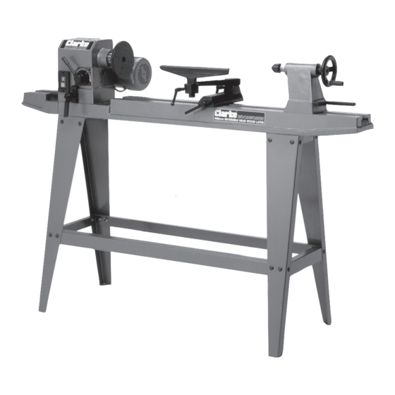
- Page 1 WOODLATHE WOODLATHE MODEL NO. CWL-20RV Part No. 6500670 OPERATING & MAINTENANCE INSTRUCTIONS 1202...
-
Page 2: Specifications
SPECIFICATIONS Motor ..............230V 50Hz 1 Phase ½ HP Induction Current rating ..........2.2 amp Max distance between centres ....850mm (35.4") Centre height turning capacity ....304mm (12") Diameter Gross weight ........... 85kg Dimensions ............1380x320x362mm Drill chuck speeds (RPM)** ......1. 500 RPM 6. -
Page 3: Table Of Contents
Thank you for purchasing your CLARKE, Variable Speed, Reversible Head, Wood Lathe. Before attempting to operate this machine, please read this instruction manual thoroughly, and follow all directions carefully. By doing so you will ensure the safety of both yourself andthat of others around you, and at the same time, you should look forward to long and trouble free service from your Wood lathe. - Page 4 GENERAL SAFETY RULES FOR OPERATING MACHINERY PARTS DIAGRAM WARNING As with all machinery, there are certain hazards involved with their operation and use. Exercising respect and caution will considerably lessen the risk of personal injury. However, if normal safety precautions are overlooked, or ignored, personal injury to the operator may result.
-
Page 5: Additional Safety Rules For Wood Lathes
• PARTS LIST ALWAYS DISCONNECT THE MACHINE before servicing or changing accessories. • AVOID ACCIDENTAL STARTING. Ensure the machine is switched OFF before No. Description Part No. Description Part No. plugging in. Headstock SD2001RV Handle Assy SD2037RV • CHECK FOR DAMAGE. If part of the machine (eg. A cover or guard), is Live Centre SD2002RV Tool Rest Extension... - Page 6 (item 28), on the end of the motor shaft, is weak and needs replacing. Consult • your local dealer, or CLARKE International Service Dept. on 0208 988 7400 When turning between centres, always ensure that the tailstock centre is snug against the workpiece, with the spindle locked, AND the Tailstock securely locked to the bed.
-
Page 7: Electrical Connections
STARTING PROCEDURE. ELECTRICAL CONNECTIONS Having prepared the lathe in accordance with the instructions given, ensure WARNING! THIS APPLIANCE MUST BE EARTHED the work is properly centralised, properly held, and is completely secure. Turn the workpiece by hand to ensure that it moves freely without interference. IMPORTANT: Connect the mains lead to a standard, 230 Volt (50Hz) electrical Remove any wood shavings, and ensure that no loose tools are in the vicinity. -
Page 8: Assembly
Speed change will only take place with the lathe running. To change speeds, pull immediately, or please call CLARKE International Parts Dept. on 020 8988 7400 out the spring loaded handle, which locks the speed change lever in place, and... - Page 9 Thoroughly clean all machined surfaces to remove any protective coating D. For Turning Between Centres that may be present. The surfaces should then be lightly oiled. For turning between centres, two hardened Morse Taper centres are provided. Gently, and with assistance, turn the bed assembly over so that it is resting on The Live Centre should be gently tapped into the work (at its exact centre - the headstock and tailstock, and to protect those components, rest them on previously marked out), using a wooden mallet, and then mounted in the...
-
Page 10: Maintenance
If the tailstock fails to move when the clamp is released, or fails to lock when the PREPARATION (Item Nos. Refer to Parts list) clamp lever is turned clockwise through approx. one third of a turn, the tailstock securing nut, beneath the tailstock (item 44), is either too loose or too tight. A.
Need help?
Do you have a question about the Woodworker CWL-20RV and is the answer not in the manual?
Questions and answers
can i buy a headstoch clamp complete for cwl-20rv