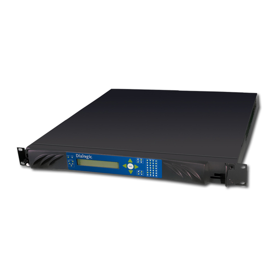
Dialogic IMG 1010 Quick Start Manual
Integrated media gateway
Hide thumbs
Also See for IMG 1010:
- Quick start manual (18 pages) ,
- Installation instructions manual (9 pages) ,
- Installation and setup manual (169 pages)

Related Manuals for Dialogic IMG 1010


Summary of Contents for Dialogic IMG 1010
- Page 1 Dialogic ® IMG 1010 Integrated Media Gateway Quick Start Guide March 2010 07-8728-05 www.dialogic.com...
-
Page 2: Hardware Limited Warranty
DIALOGIC PRODUCTS INCLUDING LIABILITY OR WARRANTIES RELATING TO FITNESS FOR A PARTICULAR PURPOSE, MERCHANTABILITY, OR INFRINGEMENT OF ANY INTELLECTUAL PROPERTY RIGHT OF A THIRD PARTY. Dialogic products are not intended for use in medical, life saving, life sustaining, critical control or safety systems, or in nuclear facility applications. -
Page 3: Table Of Contents
Table of Contents Overview ....................... 1 Shipping Information ....................1 Connecting AC Power ....................1 Power Specifications ..................... 1 AC Power Module ....................1 Connecting DC Power ....................2 Power Specifications: .................... 2 -48vdc wiring ....................... 2 Grounding IMG1010 (DC Version Only) ..............3 Procedure ....................... -
Page 4: Revision History
Revision history Revision Release date Notes 07-8728-05 April 2009 Last modified: March 2010 Refer to www.dialogic.com for product updates and for information about support policies, warranty information, and service offerings. -
Page 5: Overview
Connecting AC Power Power Specifications If the IMG 1010 is powered by AC voltage then the AC input power must conform to the specifications in the table below. Insert one end of AC cord into rear of IMG 1010 and the other end into a grounded wall outlet, uninterruptible power supply (UPS), or surge protector. -
Page 6: Connecting Dc Power
Caution: Do not wire chassis directly to other equipment or a common bus bar. The DC power module must be wired directly to a -48vdc fused power source. Power Specifications: If the IMG 1010 is powered by DC voltage, the DC input power must conform to the specifications in the table below. Operating Range... -
Page 7: Grounding Img1010 (Dc Version Only)
Welcome Grounding IMG1010 (DC Version Only) The DC version of the IMG 1010 should be connected to a true earth ground. To connect chassis to ground you will need the following equipment: 14-16 AWG machine tool wire (MTW) (green/yellow) # 10 solder-less crimp connector with two-hole mounting option to connect to grounding lug. -
Page 8: Connecting And Configuring Network Management Port „Ctrl 0
IMG 1010 along with the GCEMS server to download system software and start configuring the IMG 1010 using the ClientView GUI. On the rear of the IMG 1010 are the network interfaces. The first interface -CTRL 0- is a Fast Ethernet port dedicated to network management. -
Page 9: Installing Gcems Software
IMG_10.5.x.135.bin IMGUserInterface_10.5.x.135.bin Note: If you do not have a support contract with Dialogic, then the software supplied to you on the Software CD can be used. 3. Refer to the topics under the following headings in the Online Documentation to install the GCEMS software IMG 1010-Installation and Setup Guide >... -
Page 10: Connecting Data0 Port
Connecting DATA0 Port 1. The port DATA 0 that is located on the rear of the IMG 1010 is a Gigabit-Ethernet port and is dedicated to VoIP Bearer traffic. The DATA 0 port can be on either the same IP network as the management network, or can be connected to a separate network. -
Page 11: Connecting Tdm Signaling And Bearer Ports
Once the IMG 1010 has software installed, the cabling is connected, and the GCEMS server has been configured, the ClientView application can be used to configure the system. Below are a few topics from the Online Documentation to get started on configuring the IMG 1010 through the ClientView GUI.
Need help?
Do you have a question about the IMG 1010 and is the answer not in the manual?
Questions and answers