
Related Manuals for Dialogic BorderNet 2020


Summary of Contents for Dialogic BorderNet 2020
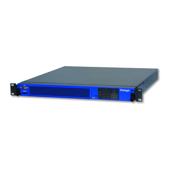
- Page 1 BorderNet 2020 Hardware Guide BorderNet 2020 hardware specifications April 26, 2011 No Doc Number www.dialogic.com...
- Page 2 All contents of this document are furnished for informational use only and are subject to change without notice and do not represent a commitment on the part of Dialogic Inc. and its affiliates or subsidiaries (“Dialogic”). Reasonable effort is made to ensure the accuracy of the information contained in the document.
- Page 3 This document discusses one or more open source products, systems and/or releases. Dialogic is not responsible for your decision to use open source in connection with Dialogic products (including without limitation those referred to herein), nor is Dialogic responsible for any present or future effects such usage might have, including without limitation effects on your products, your business, or your intellectual property rights.
-
Page 4: Table Of Contents
Table of Contents Dialogic® BorderNet™ 2020 Integrated Multimedia Gateway with BDN_EMS ..1 Getting Started ....................... 2 BorderNet 2020 - Specifications ................2 Physical Description and Specifications ............... 4 Front Panel Interfaces and LEDs ................10 Licensing ......................12 Installing the Hardware ..........Error! Bookmark not defined. -
Page 5: Dialogic® Bordernet™ 2020 Integrated Multimedia Gateway With Bdn_Ems
Dialogic® BorderNet™ 2020 Integrated Multimedia Gateway with BDN_EMS Welcome to the WebHelp documentation for the Dialogic BorderNet™ 2020 Integrated ® Multimedia Gateway. The WebHelp documentation provides installation and configuration information needed to install, setup, and configure the BorderNet 2020. -
Page 6: Getting Started
Getting Started BorderNet 2020 - Specifications Refer to the BorderNet 2020 Product Description Sheet on the Dialogic website for the latest information on supported protocols, features, and requirements... - Page 7 Dialogic Corporation or its subsidiaries. The listed hardware warranty periods and terms are subject to change without notice. For purchases not made directly from Dialogic please contact your direct vendor in connection with the warranty period and terms that they offer.
-
Page 8: Physical Description And Specifications
Configuration information provided on a sticker on the bottom of the unit ( part number, revision, serial number, and MAC). For product declarations and global approval information, see www.dialogic.com/declarations/default.htm. The following table provides the 2020 IMG physical specifications: Physical Specification Width 431 mm (16.97 in.) - Page 9 Getting Started Environmental Specifications The 2020 IMG is designed to work under the following environmental conditions: Parameter Specification Operating temperature 0° C to 50° C Operating short-term temperature -5° C to 55° C (96 hours) Storage temperature -40° C to 70° C Operating thermal shock 30°...
- Page 10 BDN_Hardware_Printed_Documentation Power and Fan Control When the tray is fully seated in the docking station and the main board receives a fully seated signal from the docking station, the power ramps up. If a fault is detected by the CPU, the main board shuts down. The 2020 IMG uses the fans on the front of the panel to draw air into the unit to cool the main board and the I/O board.
- Page 11 1. Open the shipping box and remove the packing list. 2. Review the packing list to verify that it matches what was shipped with your order. If discrepancies exist, contact a Dialogic sales representative. 3. Remove the protective cover and carefully lift the 2020 IMG from the shipping box.
- Page 12 BDN_Hardware_Printed_Documentation Rear Panel Interfaces and LEDs The following illustration shows the rear panel interfaces on the DS3/OC-3 2020 IMG: Connector Description CTRL 0, CTRL 1 Redundant 10/100/1000BaseT Ethernet connectors 10/100/1000 providing secure communication with an external host or (Ethernet control) device.
- Page 13 Getting Started 75 ohm BNC connectors supporting three DS3 links. OC-3 Small form factor pluggable optical modules. 1+1 auto- protection switching (APS) providing full link redundancy and hitless switchover in case of line failure. Ethernet LEDs RJ-45 Ethernet connectors containing one Ethernet status LED: Green/blinking green: 1000Base-T link present/1000Base-T activity Orange/blinking orange:...
-
Page 14: Front Panel Interfaces And Leds
BDN_Hardware_Printed_Documentation Front Panel Interfaces and LEDs The following illustration shows the front panel interfaces and LEDs: Connector Description UART Universal asynchronous receiver/transmitter. Requires a null modem serial cable for PC connection. Used for local access when IP connectivity is unavailable. SD MEM SD memory card slot. - Page 15 Getting Started ENET (CTRL, AUX, Green: Link present and active connection DATA A, DATA B, Yellow: Link present and standby connection DATA C, DATA D) Off: No link...
-
Page 16: Licensing
For example, an existing license could have the _old extension added to it. (Ex. 12345678_20100726043030_old.cfg) 2. Transfer new license as a dialogic user to the /opt/dialogic/common/license directory. 3. Open ClientView and Right-click the node being queried and select Licensing Info and click on commit. - Page 17 Getting Started License Validation Failure The following icon displays on the Physical Node object in the WebUI page tree: A license validation has failed. Verify the serial number for license is serial number of 2020 IMG. See License Info page. Licensed Components License Description...
- Page 18 BDN_Hardware_Printed_Documentation licensed. When initially purchasing the 2020 IMG, the licenses are sold as 1 DS3, 2 DS3's, or 3 DS3's. Once the initial license bundle is created, the TDM ports can then be licensed in 32 port increments. Table 1 below displays the increments that the licenses are created.
-
Page 19: Locating The Base Mac Address
Pre-Installation Considerations The 2020 IMG has the following location requirements: 2020 IMG Location requirements -48 V DC Restricted area, such as a dedicated equipment room or limited access office with access only by trained personnel. 120/240 V AC Does not have to be in a restricted area. Can be located in a clean and well-ventilated office space. -
Page 20: Channel Service Units
BDN_Hardware_Printed_Documentation Twisted wire reduces induction, and thus interference, from one wire to the other. Varying the length of twists reduces the potential for signal interference between pairs. Twisted pair wiring is available in various thicknesses. Thicker cable covers longer distances and provides better sound quality, but it is more expensive. Channel Service Units A channel service unit (CSU) connects a digital phone line (T1/E1) from the telephone company to a digital communications device. -
Page 21: Installing The 2020 Img In A Rack
Installing the Hardware Rack Mounting The 2020 IMG can be front-mounted or mid-mounted in a 482.6 mm (19-inch) rack. It is shipped with the brackets in the front mounting position. The brackets are movable and reversible to accommodate two mid-mounting positions. A front-mounted 2020 IMG requires rear mounting brackets to secure the back corners. -
Page 22: Installing The Rear Mount Bracket Kit
BDN_Hardware_Printed_Documentation Complete the following steps to rack mount the 2020 IMG: 1. Review the Pre-Installation Considerations. 2. Position the mounting brackets for either front or mid-mounting. 3. Align the holes on the mounting bracket ears to the mounting holes on the rack. 4. - Page 23 Installing the Hardware Complete the following steps to install the rear mount bracket kit: 1. Install the fixed brackets to the 2020 IMG using 6-32 flat head screws. 2. Tighten the screws. 3. Place the sliding brackets onto the fixed brackets and install the 6-32 pan head screws loosely to permit movement.
-
Page 24: Ds3/Oc-3 2020 Img Grounding Lug
To connect a true earth ground to the 2020 IMG, use 10, 12, or 14 AWG machine tool wire (MTW) (green/yellow for earth ground). Dialogic supplies a two hole #10 solderless crimp grounding lug that is attached to the grounding screws on the rear of the 2020 IMG. -
Page 25: Ac Power Cables
SLM-CBL-1007R AC power cable - Israel Additional AC power cables are available upon request. Contact your Dialogic sales representative for more information. Warning! Do not attempt to modify or use the supplied AC power cord if it is not the exact type required. - Page 26 BDN_Hardware_Printed_Documentation Connecting AC Power Redundant, hot-swappable AC power modules are located at the rear of the docking station. AC power modules must be plugged into three-prong grounded outlets. The power up sequence can only start when the tray is fully seated in the docking station. This ensures that the main board does not power up until the system is properly seated.
- Page 27 Installing the Hardware This connector allows the docking station to interface with all variations of AC outlets using a standard power cable with a compatible outlet plug.
-
Page 28: Dc Power Cables
BDN_Hardware_Printed_Documentation DC Power Cables A 500 mm DC power pigtail cable is included with DC systems. If you require a longer cable, a 4 m cable is available for order (P/N BDN-CBL-1000). Caution: The color specifications for the DC power cables are not identical. Be sure to review the specifications that are shipped with your cable before installation. -
Page 29: Connecting To A Single Dc Power Source
Installing the Hardware Connecting DC Power Redundant, hot-swappable DC power modules are located at the rear of the docking station. The power up sequence can only begin when the tray is fully seated in the docking station. This ensures that the main board does not power up until the system is properly seated. Connecting to a Single DC Power Source To connect a single external DC power source to the 2020 IMG: 1. - Page 30 BDN_Hardware_Printed_Documentation Caution: Do not daisy-chain two or more systems. Do not wire the 2020 IMG directly to other equipment or to a common bus bar.
-
Page 31: Connecting To The Network
Connecting to the Network Complete the following steps to connect the 2020 IMG to the network: 1. Refer to the Installing the Software section in the Dialogic® BorderNet™ 2020 Integrated Multimedia Gateway WebHelp. 2. Review the options for installing the software and choose the appropriate installation method for your site. -
Page 32: Cable Specifications
BDN_Hardware_Printed_Documentation Cable Specifications The 2020 IMG can be connected as a single platform or in a redundant platform configuration. The I/O cables must meet the following specifications: Cable Specifications 10/100/1000Base- 100/1000Base-T (shielded) Category 5: T (shielded) Ethernet Twisted pair Maximum 100 m segment length 24 gauge, 100 ohm shielded twisted pair 8-pin RJ-45 connector T1 (shielded) Category 8:... -
Page 33: Cabling Multiple Subnets
Installing the Hardware Cabling Multiple Subnets The 2020 IMG can be configured in a number of different ways. This topic illustrates the following cabling options: Configuring and Cabling Two Subnets Configuring and Cabling Three Subnets The following illustration provides a high-level overview of how to cable and configure the system: For more information, refer to IP Address topic. - Page 34 BDN_Hardware_Printed_Documentation 10.10.30.101 DATA A0 IP bearer Network Media Redundant data Interfaces interface 1 data page The following illustration shows the cabling for combining the signaling and data on one subnet and the control on a separate subnet: Configuring and Cabling Three Subnets To configure the 2020 IMG to use three subnets, control, data, and signaling are each on their respective subnets.
- Page 35 Installing the Hardware DATA A0 IP bearer Network 10.10.50.100 Media Redundant data Interfaces interface 0 data page IP bearer Network 10.10.50.101 Media Redundant DATA A0 data Interfaces interface 1 data page The following illustration shows the cabling for three subnets:...
-
Page 36: Cabling For Redundancy
BDN_Hardware_Printed_Documentation Cabling for Redundancy This topic provides an example of the following redundant cabling scenarios: Redundant Control Redundant Data Redundant Signaling Redundant SS7 Signaling Redundant Control To cable for redundant control, the CTRL 0 and CTRL 1 ports use the same IP address. Use either BootP or the SD card to configure the CTRL 0 and CTRL 1 MAC address: CTRL 1 MAC address = CTRL 0 MAC address + 1 For more information, refer to dhcp.conf. - Page 37 Installing the Hardware Redundant Data Configure a shared IP address for DATA A0 and DATA A1 through the WebUI. Use these Ethernet DATA ports to communicate between the 2020 IMG and the IP network. These ports can be used for RTP streams or SIP signaling. VoIP Module 0 and Module 1 send RTP data between the Ethernet data ports within the 2020 IMG.
- Page 38 BDN_Hardware_Printed_Documentation Redundant Signaling Configure a shared IP address for DATA B0 and DATA B1 through the WebUI. Use these Ethernet DATA ports to communicate between the 2020 IMG and the IP network. The following illustration shows the cabling for redundant VoIP signaling:...
- Page 39 Installing the Hardware Redundant SS7 Signaling The following illustration shows the cabling for redundant SS7 signaling:...
- Page 40 BDN_Hardware_Printed_Documentation...
- Page 41 Installing the Hardware Troubleshooting the Hardware The following table addresses some of the hardware issues that may during the 2020 IMG hardware installation. Problem Cause Solution DC 2020 IMG powers Power source failed or does not Ensure external power up, but then shuts provide the required level of source is functioning at the down.
- Page 42 ALARM LED Connectors and LEDs. If lights red (major) or ALARM LED is still red, orange (minor) contact Dialogic Technical Support. 2020 IMG continuously Software was not obtained within This behavior is normal reset once it is required time frame (generally...
Need help?
Do you have a question about the BorderNet 2020 and is the answer not in the manual?
Questions and answers