Table of Contents
Advertisement
Quick Links
Advertisement
Table of Contents

Related Manuals for Intermec ScanPlus 1800ST


Summary of Contents for Intermec ScanPlus 1800ST
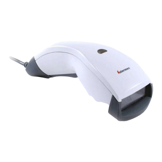
- Page 1 Service Manual ScanPlus 1800ST Scanner...
- Page 2 The information contained herein is proprietary and is provided solely for the purpose of allowing customers to operate and/or service Intermec manufactured equipment and is not to be released, reproduced, or used for any other purpose without written permission of Intermec.
-
Page 3: Table Of Contents
Contents Contents Before You Begin v Warranty Information v Safety Summary v Warnings, Cautions, and Notes vi About This Manual vi Repairing the 1800 Cautions 1-3 Ordering Replacement Parts 1-3 Replacing Parts 1-4 Spare Parts List 1-4 Disconnecting the Cable 1-5 Opening the 1800 1-7 Assembling the 1800 1-8 Replacing the Top Shell Assembly 1-9... -
Page 5: Before You Begin
To receive a copy of the standard warranty provision for this product, contact your local Intermec support services organization. In the U.S. call 1-800-755-5505, and in Canada call 1-800-668-7043. If you live outside of the U.S. or Canada, you can find your local Intermec support services organization on the Intermec Web site at www.intermec.com. -
Page 6: Warnings, Cautions, And Notes
ScanPlus 1800ST Service Manual Warnings, Cautions, and Notes The warnings, cautions, and notes in this manual use this format: Warning A warning alerts you of an operating procedure, practice, condition, or statement that must be strictly observed to avoid death or serious injury to the persons working on the equipment. -
Page 7: Repairing The 1800
Repairing the 1800... -
Page 9: Cautions
Repairing the 1800 This chapter explains how to open, assemble, and repair the ScanPlus 1800. It also gives preliminary cautions to follow when servicing the 1800. Cautions Because finger oils can dissolve the reflective coating of the plastic mirrors, always wear finger cots or non-powdered latex gloves when handling optical parts. -
Page 10: Replacing Parts
ScanPlus 1800ST Service Manual Replacing Parts The next illustration shows the parts of the 1800. 1800M001.eps Spare Parts List Callout Description Number Part Number Front rubber enclosure 3-360039-31 Exit window 3-360039-31 Top shell assembly 3-360039-30 Trigger spring 3-360039-31 Bottom shell assembly... -
Page 11: Disconnecting The Cable
Repairing the 1800 Disconnecting the Cable The 1800 uses either the old standard cable boot or the new easy-to-use boot. All cables marked Rev: 10 or higher use the new boot, while all cables marked Rev: 09 or lower use the old boot. Caution Do not attempt to remove the cable without following the correct procedure for the boot type, or you will damage the shell of the 1800. - Page 12 ScanPlus 1800ST Service Manual To remove cables marked Rev: 09 or lower 1. Pull back on the cable boot while holding the 1800. 1800M003.eps 2. Pull the cable boot away from the 1800. Do not twist the cable boot. 1800M005.eps...
-
Page 13: Opening The 1800
Repairing the 1800 Opening the 1800 To open the 1800, you need the following tools: Small straight slot screwdriver Pliers or vise Finger cots or non-powdered latex gloves To open the 1800 1. Use a small straight slot screwdriver to unclip the two clips at the base of the 1800. Note: You can expect the clips to break during this procedure, but do not damage the connector PCB or the bottom shell of the 1800. -
Page 14: Assembling The 1800
ScanPlus 1800ST Service Manual 3. Wearing gloves or finger cots, hold the top and bottom shells at the window and pull the shells apart. 1800M015.eps Assembling the 1800 To assemble the 1800, you need the following tools: Compressed air Super glue To assemble the 1800 1. -
Page 15: Replacing The Top Shell Assembly
Repairing the 1800 Replacing the Top Shell Assembly To replace the top shell assembly, you need the following parts: Top shell assembly (Part No. 3-360039-30) To replace the top shell assembly 1. Open the 1800. For help, see “Opening the 1800” on page 1-7. 2. - Page 16 ScanPlus 1800ST Service Manual 3. Remove and retain the buzzer cap. 1800M019.eps 4. Remove the front rubber enclosure. 1800M023.eps 1-10...
-
Page 17: Replacing The Exit Window Or Front Rubber Enclosure
Repairing the 1800 5. Gently pry one side of the bottom shell out and remove that side of the main PCB assembly. Repeat for the other side. If you are replacing the trigger spring, continue with Step 6; otherwise, go to Step 7. Trigger spring 1800M025.eps... - Page 18 ScanPlus 1800ST Service Manual 2. Wearing finger cots or non-powdered Latex gloves, remove and retain the exit window. 1800M017.eps If you are replacing the exit window only, insert a new exit window into the front rubber enclosure (black screen print facing the interior of the scanner), and then follow the procedure “Assembling the 1800”...
-
Page 19: Replacing The Main Pcb Assembly
Repairing the 1800 4. Place the Caution labels on the new front rubber enclosure. 5. To reassemble the 1800, reverse Steps 2 through 3 using a new front rubber enclosure, and then follow the procedure “Assembling the 1800” on page 1-8. Replacing the Main PCB Assembly To replace the main PCB assembly, you need the following tools: Finger cots or non-powdered Latex gloves... - Page 20 ScanPlus 1800ST Service Manual 2. Wearing finger cots or non-powdered Latex gloves, remove and retain the exit window. 1800M017.eps 3. Remove and retain the buzzer cap. 1800M019.eps 4. Remove the front rubber enclosure. 1800M023.eps 1-14...
-
Page 21: Replacing The Laser Absorber, Buzzer Cap, Or Laser Frame
Repairing the 1800 5. Gently pry one side of the bottom shell out and remove that side of the main PCB assembly. Repeat for the other side. Scan engine Main PCB assembly Connector flex Trigger spring 1800M050.eps 6. Remove and retain the three screws securing the laser frame to the main PCB assembly. - Page 22 ScanPlus 1800ST Service Manual To replace the laser absorber, buzzer cap, or laser frame 1. Open the 1800. For help, see “Opening the 1800” on page 1-7. 2. Wearing finger cots or non-powdered Latex gloves, remove the exit window. 1800M017.eps 3.
- Page 23 Repairing the 1800 5. Gently pry one side of the bottom shell out and remove that side of the main PCB assembly. Repeat for the other side. Scan engine Main PCB assembly Connector flex Trigger spring 1800M050.eps 6. Remove and retain the two screws securing the scan engine to the laser frame. If you are replacing only the laser absorber, reassemble the 1800 following the procedure on page 1-8 using a new laser absorber;...
-
Page 24: Replacing The Scan Engine
ScanPlus 1800ST Service Manual 9. To reassemble the 1800, reverse Steps 2 through 8 using a new laser frame, and then follow the procedure “Assembling the 1800” on page 1-8. Replacing the Scan Engine To replace the scan engine, you need the following tools:... - Page 25 Repairing the 1800 4. Remove the front rubber enclosure. 1800M023.eps 5. Gently pry one side of the bottom shell out and remove that side of the laser frame. Repeat for the other side. Scan engine Main PCB assembly Connector flex Trigger spring 1800M050.eps...
-
Page 26: Replacing The Connector Pcb Assembly
ScanPlus 1800ST Service Manual Replacing the Connector PCB Assembly To replace the connector PCB assembly, you need the following tools: Finger cots or non-powdered Latex gloves You will need the following part: Connector PCB assembly (Part No. 3-360039-33) To replace the connector PCB assembly 1. - Page 27 Repairing the 1800 4. Remove and retain the front rubber enclosure. 1800M023.eps 5. Gently pry one side of the bottom shell out and remove that side of the main PCB assembly. Repeat for the other side. 1800M025.eps 1-21...
-
Page 28: Connecting The Cable
ScanPlus 1800ST Service Manual 6. Disconnect the connector flex cable from the main PCB assembly. Main PCB Connector PCB 1800M029.eps 7. To reassemble the 1800, reverse Steps 2 through 6 using a new connector PCB assembly, and then follow the procedure on page 1-8. - Page 29 Repairing the 1800 2. Slide the boot along the cable. 1800M035.eps 3. Slide the cable boot inside the 1800. When the boot is in the correct position, you hear a click. 1800M007.eps 1-23...
- Page 30 ScanPlus 1800ST Service Manual 4. Gently pull the cable to be sure it is not folded inside the boot. 1800M039.eps To connect cables marked Rev: 09 or lower 1. Insert the connector into the 1800. 2. Place the lower part of the cable boot inside the 1800.
- Page 31 Repairing the 1800 3. Push the upper part of the cable boot into the 1800. 1800M043.eps 1-25...
-
Page 33: Testing And Upgrading The 1800
Testing and Upgrading the 1800... -
Page 35: Testing The 1800
Testing and Upgrading the 1800 This chapter explains how to test the 1800 and upgrade the cable firmware. Testing the 1800 You must test the 1800 after you have serviced it. Test Conditions Lighting Indoor office or factory lighting or darker is acceptable. Choose an area with consistent light levels away from extreme light sources. - Page 36 ScanPlus 1800ST Service Manual 3. Set the communications settings on your PC to: Baud: 57600 Parity: None Flow control: None Data bits: 7 Stop bits: 2 4. Scan the following reset bar code. reset factory defaults \46\42\60 If the scanner does not come on when you pull the trigger, the scanner may be in laser emulation or wand emulation mode.
-
Page 37: Test Parameters
To upgrade the 1800 firmware 1. Download the latest version of EasySet (version 4.1 or later). a. Point your Web browser to http://datacapture.intermec.com. b. Click Software from the Software menu, and then click EasySet. c. Click Windows95/98/NT/2000, and then download EasySet. -
Page 38: Upgrading The Smart Cable Firmware
To upgrade the smart cable firmware 1. Download the latest version of EasySet (version 4.1 or later). a. Point your Web browser to http://datacapture.intermec.com. b. Click Software from the Software menu, and then click EasySet. c. Click Windows95/98/NT/2000, and then download EasySet. - Page 40 Corporate Headquarters 6001 36th Avenue West Everett, Washington 98203 tel 425.348.2600 fax 425.355.9551 www.intermec.com ScanPlus 1800ST Scanner Service Manual *072378-001* *072378-001*...
Need help?
Do you have a question about the ScanPlus 1800ST and is the answer not in the manual?
Questions and answers