
Related Manuals for Bertazzoni MAS486GGASXTLP


Summary of Contents for Bertazzoni MAS486GGASXTLP
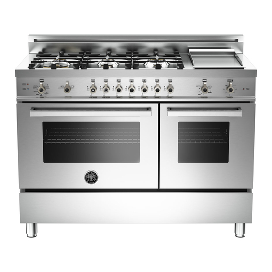
- Page 1 INSTALLATION, USE & CARE MANUAL FREESTANDING GAS RANGES DIMENSIONS: 48’’ (1220 mm)(W) x 253/16’’ (640 mm)(D) x36’’ (915 mm)(H) Model MAS486GGASXTLP [MTYKQPA7X2AUA] 310831 ...
- Page 2 From the desk of the President Dear new owner of a Bertazzoni product, I want to thank you for choosing one of our beautiful PRO ranges. We know that you have many brands and products to choose from and we are thrilled that you have decided to take onw of your products into your home. We take as much pride in making our ranges as we hope you will in owning them. My family started manufacturing cooking appliances in 1882. Each of BERTAZZONI SpA our products is a blend of Italian design finess and Via Palazzina 8 superior appliance technology. While we can not 42016 Guastalla RE replace your unique talent at cooking delicious ITALY recipes for yourself, your family and your friends, we try our best to make cooking easier, more effective and more fun. WWW.BERTAZZONI‐ITALIA.COM Our appliances are designed according to the strictest safety and performance standard for the European and the North American market. We follow the most advanced manufacturing philosophy. Each appliance leaves the factory after thorough quality inspection and testing. Our distributors and our service partners are ready to answer any questions you may have regarding how to install, use and care for your Bertazzoni product. This manual will help you learn to use the product in the safest and most effective manner and care ...
-
Page 3: Table Of Contents
TABLE OF CONTENTS WARRANTY AND SERVICE ...................... 4 CUSTOMER SERVICE ............................... 4 REPLACEMENT PARTS .............................. 4 IMPORTANT SAFETY INFORMATION .................... 5 PRODUCT SPECIFICATIONS ...................... 6 INSTALLING THE LEGS ........................ 8 INSTALLING THE WORKTOP FRONTGUARD .................. 8 INSTALLING THE BACKGUARD ...................... 9 INSTALLING THE ANTI‐TIP STABILLTY DEVICE ................ 10 INSTALLATION REQUIREMENTS .................... 10 ELECTRICAL .................................. 10 GAS .................................... 10 INSTALLATION ADJACENT TO KITCHEN CABINETS .............. 11 EXHAUST HOOD INSTALLATION .................... 11 ELECTRICAL CONNECTION ...................... 12 WIRING DIAGRAM ................................ 12 GAS CONNECTION ........................ 13 GAS CONNECTION ........................ 13 PRESSURE... -
Page 4: Warranty And Service
WARRANTY AND SERVICE All Bertazzoni products carry a 2 year parts and labor warranty. Service on all Bertazzoni products shall be carried out by factory‐trained professionals only. For warranty service please contact Customer Service at the numbers indicated below. CUSTOMER SERVICE English/spanish hotline (866) 905‐0010 French (800) 561‐7625 Fax (714) 428‐0040 Email BERTAZZONIHELP@SERVICEPOWER.COM Mailing address SERVICEPOWER 1503 South Coast drive Suite 320 Costa Mesa CA 92626 REPLACEMENT PARTS Only Bertazzoni replacement parts may be used in performing service on the appliance. Replacement parts are available from factory authorized parts distributors. AP Wagner PHONE FAX 716 961 7131 716 856 4779 Reliable Parts PHONE ... -
Page 5: Important Safety Information
WARNING! IMPORTANT SAFETY INFORMATION Read this instruction booklet before installing PLEASE READ AND FOLLOW THESE IMPORTANT and using the appliance. INSTRUCTIONS FOR THE SAFETY OF YOUR HOME AND OF THE PEOPLE LIVING IN IT. The manufacturer will not be responsible for any damage to property or to persons caused by Save this Manual for local electrical inspector’s incorrect installation or improper use of the use. appliance. Read and save these instructions for future The manufacturer reserves the right to make reference. changes to its products when considered Observe all governing codes, ordinances and necessary and useful, without affecting the regulations. essential safety and operating characteristics. WARNING! This appliance has been designed for non‐ If the information in this manual is not followed ... -
Page 6: Product Specifications
PRODUCT SPECIFICATIONS Dimensions (insert drawings front, side and back Weight Burner power Natural gas LP gas Auxiliary 3750 BTU/h 3750 BTU/h Semi‐rapid 6000 BTU/h 6300 BTU/h Rapid 10400 BTU/h 11400 BTU/h Dual burner (inner) 2730 BTU/h 2900 BTU/h Dual burner ( outer) 15000 BTU/h 16400 BTU/h Oven (left cavity) 14500 BTU/h 14500 BTU/h Broiler (left cavity) 12000 BTU/h 12000 BTU/h Oven (right cavity) 7000 BTU/h 7000 BTU/h ... - Page 7 BEFORE INSTALLATION WARNING! This appliance shall only be installed by an authorized professional. Do not use aerosol sprays in the vicinity of this appliance while it is in operation This appliance shall be installed in accordance with the manufacturer’s installation instructions. ROOM VENTILATION: An exhaust fan may be used with the appliance; in each case it shall be This appliance must be installed in accordance installed ...
-
Page 8: Installing The Legs
INSTALLING THE LEGS INSTALLING THE WORKTOP FRONTGUARD Bertazzoni ranges must be used only with the legs properly installed. To increase the clearance between the front edge of the worktop and the burners it is possible to Four height‐adjustable legs are shipped with the install the worktop frontguard shipped with the range in the polysterene container situated over appliance. the appliance. To install the front guard, hold it with the pointed Before installing the legs, position the appliance edges looking up. Align the edges of the ... -
Page 9: Installing The Backguard
Install the front part of the backguard by INSTALLING THE BACKGUARD tightening the 2 central screws from the top and The backguard must be installed prior to 2 lateral screws from the bottom. operation of the appliance for appropriate ventilation of the oven compartment. The supplied backguard is a 2‐part assembly. The box also contains a set of metal screws for securing the backguard to the worktop. Position the back part of the backguard and Disassemble the backguard and position the front secure it to the worktop tightening 4 screws from ... -
Page 10: Installing The Anti‐Tip Stabillty Device
INSTALLATION REQUIREMENTS INSTALLING THE ANTI‐TIP STABILlTY DEVICE ELECTRICAL The anti‐tip bracket shipped with the range must be properly secured to the rear wall as shown in A properly‐grounded horizontally‐ mounted the pircture below. electrical receptacle should be installed no higher The height of the bracket from the floor must be than 3" (7.6 cm) above the floor, no less than 2” determined after the range legs have been (5 cm) and no more than 8” (20,3 cm) from the adjusted to the desired height and after the right side (facing product). range has been leveled. Check all local code requirements. Measure the distance from the floor to the bottom of the anti‐tip bracket receptacle on the back of the appliance. GAS Position the two anti‐tip brackets on the wall at An agency‐approved, properly‐sized manual shut‐ the desired height plus 1/8" (0.32 cm). The off valve should be installed no higher than 3" brackets must be placed at 2”5/16 (6,0 cm) from (7.6 cm) above the floor and no less than 2” (5 the side of the range. The distance between the cm) and no more than 8” (20.3 cm) from the left two bracket is 43”1/4 (109.8 cm). side (facing product). Secure the brackets to the wall with appropriate To connect gas between shut‐off valve and hardware. regulator, use agency‐approved, properly sized Slide the range against the wall until the brackets flexible or rigid pipe. Check all local code are fully inserted into their receptacles on the requirements. ... -
Page 11: Installation Adjacent To Kitchen Cabinets
EXHAUST HOOD INSTALLATION This range will best perform when used with PRO INSTALLATION ADJACENT TO KITCHEN line Bertazzoni exhaust hoods. These hoods have CABINETS been designed to work in conjunction with the This range may be installed directly adjacent to Bertazzoni range and have the same finish for a existing countertop high cabinets (36" or 91.5 cm perfect look. from the floor). For maximum performance, the height of the For the best look, the worktop should be level bottom of the hood from the worktop should be with the cabinet countertop. This can be between 25 1/2" (65 cm) and 31 1/2" (80 cm). ... -
Page 12: Electrical Connection
WARNING! ELECTRICAL SHOCK HAZARD ELECTRICAL CONNECTION Disconnect electrical power at the circuit This unit is manufactured for a polarized, breaker box or fuse box before installing the grounded 120 volt/60 Hz, 16 amp system. appliance. Electric power consumption is about 1200 W. Provide appropriate ground for the appliance. The minimum of 102 VAC is required for proper Use copper conductors only. operation of gas ignition systems. Failure to follow these instructions could result The circuit must be grounded and properly in serious injury or death polarized. The unit is equipped witth a SJT power cord. In CAUTION ... -
Page 13: Gas Connection
MANUAL SHUT‐OFF VALVE GAS CONNECTION THIS VALVE IS NOT SHIPPED WITH THE APPLIANC All gas connections must comply with national AND MUST BE SUPPLIED BY THE INSTALLER. and local codes. The gas supply line (service) The manual shut‐off valve must be installed in must be the same size or greater than the inlet the gas service line between the gas hook‐up on line of the appliance. This range uses a 1/2" NPT the wall and the appliance inlet, in a position inlet (see drawing below for details of gas where it can be reached quickly in the event of an connection). On all pipe joints use appropriate emergency. sealant resistant to gas. In Massachusetts: A 'T' handle type manual gas This range can be used with Natural or valve must be installed in the gas supply line to LP/Propane gas. The range is shipped from the this appliance. factory for use with LP /Propane gas. For Natural household installation, the appliance must be converted by the dealer, by a factory‐ FLEXIBLE CONNECTIONS trained professional or by a qualified licensed In case of installation with flexible couplings plumber or gas service company. and/or quick‐disconnect fittings, the installer Gas conversion is important for safe and effective ... - Page 14 PRESSURE REGULATOR Since service pressure may fluctuate with local demand, every gas cooking appliance must be equipped with a pressure regulator on the incoming service line for safe and efficient operation. The pressure regulator shipped with the appliance has has two female threads ½” NPT. The regulator shall be installed properly in order ...
-
Page 15: 1. Pressure Regulator
STEP 1: PRESSURE REGULATOR GAS CONVERSION The pressure regulator supplied with the appliance is a convertible type pressure regulator WARNING! for use with LP/Propane Gas at a nominal outlet Before carrying out this operation, disconnect pressure of 11” w.c. or Natural gas at a nominal the appliance from gas and electricity. outlet pressure of 4” w.c. and it is pre‐arranged from the factory to operate with one of these Gas conversion shall be conducted by a factory‐ gas/pressure as indicated in the labels affixed on trained professional. the appliance, package and Instruction booklet. Call the customer service hotline to identify a To convert the regulator for use with other factory‐trained professional near your home. natural gas: The gas conversion procedure for this range 1. Unscrew by hand the upper cap of the includes 6 steps: regulator, remove the white plastic 1. Pressure regulator attachment from the cap, reverse its direction and screw it again firmly against the 2. Surface burners cap. The white plastic attachment has arrows 3. Main oven burner indicating the position for LP gas (LP ) and ... - Page 16 STEP 3: MAIN OVEN BURNER STEP 2: SURFACE BURNERS To replace the nozzles of the main oven burner, To replace the nozzles of the surface burners, lift start by removing the bottom panel of the oven. up the burners and unscrew the nozzles shipped with the range using a 7 mm {sochet wrench). Replace nozzles using the conversion set supplied with the range or by a Bertazzoni authorized parts warehouse. Each nozzle has a number indicating its flow diameter printed on the body. Consult the table on page 20 for matching nozzles to burners. Loosen the screw located on the right side of the burner and pull out the burner from its support. ATTENTION: pay extra attention to avoid damage to the igniter and thermocouple. Left oven ...
- Page 17 Replace the nozzle using the conversion set Left oven supplied with the range or by a Bertazzoni authorized parts warehouse. Each nozzle has a number indicating its flow diameter printed on the body. Consult the table on page 20 for ...
-
Page 18: Burner
Using a 7 mm [name of the tool] unscrew the nozzle. Replace the nozzle using the conversion set supplied with the range or by a Bertazzoni authorized parts warehouse. Each nozzle has a number indicating its flow diameter printed on ... -
Page 19: Step 6: Minimum Flame Adjustment
OVEN BURNER 1. Set the oven temperature control knob to the MAXIMUM setting. 2. Close the oven door and operate the oven for at least 10 minutes. 3. Set the knob to the MINIMUM setting Remove the knob. 4. With a slotted screwdriver turn the choking screw (by‐pass screw at the left side of the thermostat bar) and, while observing the flame ... - Page 20 Model ] MTYKQPA7X2AUA M A S 4 8 6 G G AS X T L P Burner Position Injector Pressure Max Rate Min Rate By-pass diam. [mm.] Type [i.w.c.] [BTU/h] [BTU/h] diam. [mm] Auxiliary Front R 0,92 NG 4" ...
-
Page 21: Installation Checkllst
INSTALLATION CHECKLlST FINAL PREPARATION 1. Is the range mounted on its legs? Before using the oven, remove any protective wrap from the stainless steel. 2. Is the backguard securely connected? All stainless steel body parts should be wiped with hot, soapy water and with a liquid stainless 3. Has the anti‐tip device been properly steel cleanser. installed? If buildup occurs, do not use steel wool, abrasive cloths, cleaners, or powders! If it is necessary to 4. Does the clearance from the side cabinets scrape stainless steel to remove encrusted comply with the manufacturers directions? materials, soak with hot, wet cloths to loosen the material, then use a wood or nylon scraper. Do 5. Is the electricity properly grounded? not use a metal knife, spatula, or any other metal tool to scrape stainless steel! Scratches are 6. Is the gas service line connected following almost impossible to remove. the directions of the manufacturer? Before using the oven for food preparation, wash the cavity thoroughly with a warm soap and 7. Have all the proper valves, stoppers and water solution to remove film residues and any dust or debris from installation, then rinse and gasket been installed between the range and wiped dry. the service line? 8. -
Page 22: User Manual
USER MANUAL SURFACE BURNER LAYOUT WARNING! Reflect names from brochure 1. Small Burner Do not to cover the holes inside the oven with 2. Medium burner aluminium foil. 3. Rapid burner Do not to cover the worktop with aluminium 4. Dual burner (Power burner) foil. 5. Griddle Do not store any flammable object or objects under pressure in the storage compartment. Keep the area of operation of the range free from combustible materials, gasoline and other flammable vapors and liquid. Do not store dangerous or flammable materials in the cabinets above the appliance. Do not use the appliance for space heating. Do not use aerosol sprays in the vicinity of the appliance while cooking. Do not sit or step on the oven door. Do not use oven compartment for storage. ... -
Page 23: Surface Cooking
SURFACE COOKING SURFACE BURNER OPERATION SYMBOLS THERMOCOUPLE SAFETY VALVE Each surface burner of a Bertazzoni range is equipped with a thermocouple safety device. The thermocouple opens the flow of gas to the burner only when hot. Should the flame go off, the thermocouple will immediately close the gas flow to the burner eliminating any risk to your ... -
Page 24: Tips For Using Burners Correctly
TIPS FOR USING BURNERS CORRECTLY TIPS FOR USING PANS CORRECTLY WARNING! ATTENTION! KEEP CHILDREN AT A SAFE DISTANCE FROM THE Always ensure that bottom and handles of pans APPLIANCE DURING OPERATION. do not protrude from the worktop. DO NOT ALLOW CHILDREN TO OPERATE THE When cooking with flammable fat such as oil, do APPLIANCE. not leave the range unattended. 1. Always check that the burner caps are Use pots of the appropriate size on each burner properly installed before operation. following the indication of the diagram below. Burner Recommended pan size inches (mm) Small 3½”‐51/2”(90 – 140) ... -
Page 25: Tips For Using Electric Griddle
TIPS FOR USING ELECTRIC GRIDDLE WARNING! Griddle cooking recommendations The griddle element is hot after use. Allow sufficient time for griddle components cool FOOD KNOB POSITION SETTING Eggs 300°F to 325°F before cleaning. (150°C to 160°C) Bacon; Breakfast 350°F to 375°F The electric griddle element is rated 120 volts AC Sausage (177°C to 190°C) Toasted 325°F to 350°F... -
Page 26: Oven Cooking
Recommended control knob position for burner ignition Oven compartment light 275F Mimimum oven temperature OVEN SHELVES setting Bertazzoni ranges are equipped with commercial grade shelves and a enamel cooking tray. 500F Maximum oven temperature Shelves are mounted on the appropriate guides setting situated on the sides of the oven compartment. Insert the shelf between top and bottom guide in Oven on/off ... -
Page 27: Gas Oven Operation
THERMOCOUPLE SAFETY VALVE knob for 1 sec. And relase it, the automatic Bertazzoni gas ovens are equipped with a ignition system will automatically generate the thermocouple safety device and a thermostat to spark for 5 seconds and will engage the ... -
Page 28: Convection Cooking
ELECTRIC IGNITION CONVECTION COOKING Warning: Do not use the gas oven or broiler in Bertazzoni gas oven are equipped with a case of electric power failure CONVECTION fan. Open the oven door, turn the knob to the broiler In convection mode, the fan situated at the back position setting, press well the knob for 1 sec. of the oven compartment creates horizontal And relase it, the automatic ignition system will forced‐air circulation. The advantages of ... -
Page 29: Maintaining Your Range
Cleaning the burner caps: lift the burner caps from the burner heads and wash them in a warm COOLING FAN FAILURE soap and water solution. Dry thoroughly before using them again. Before reinstalling them on the Bertazzoni ranges are equipped with a cooling burner head, check that the gas flow holes are fan. The fan starts operating each time the oven not clogged with food residues or cleaning knob is on a position different from 0 (zero). ... -
Page 30: Cleaning Inside Of Oven Glass
salt, tomato sauce, etc.). Use a rubber spatula to Caution: do not loosen the hinges if the inner remove fat residues. glass is not mounted on the door. Cleaning glass door: clean the glass using a non‐ Clean the inside of the oven: To facilitate abrasive sponge or wipe with a warm soap and intensive cleaning of the oven is easy to warm water solution. Use a rubber spatula to disassemble the door by following the below remove fat residues. ... -
Page 31: Important Appliance Information
IMPORTANT APPLIANCE INFORMATION MODEL ______________________________________________________________ DATE INSTALLED _______________________________________________________________ DEALER _______________________________________________________________ _______________________________________________________________ INSTALLER _______________________________________________________________ ________________________________________________________________ SERVICER _______________________________________________________________ ... - Page 32 BERTAZZONI SpA Via Palazzina 8 42016 Guastalla RE ITALY WWW.BERTAZZONI.COM ...
Need help?
Do you have a question about the MAS486GGASXTLP and is the answer not in the manual?
Questions and answers