Table of Contents
Advertisement
Quick Links
Advertisement
Table of Contents

Subscribe to Our Youtube Channel
Related Manuals for Commell LV-677


Summary of Contents for Commell LV-677
- Page 1 LV-677 Mini-ITXexpress Motherboard User’s Manual Edition 1.1 2006/9/11...
- Page 2 LV-677 User’s Manual Copyright Copyright 2006, all rights reserved. This document is copyrighted and all rights are reserved. The information in this document is subject to change without prior notice to make improvements to the products. This document contains proprietary information and protected by copyright. No part of this document may be reproduced, copied, or translated in any form or any means without prior written permission of the manufacturer.
-
Page 3: Packing List
LV-677 User’s Manual Packing List: Please check the package content before you starting using the board. Hardware: LV-677 or LV-677DC Mini ITX Motherborad x 1 Cable Kit: 44-pin 44-pin 40-pin ATA33 IDE Cable x1 Floppy Cable x 1 SATA Cable x 2... - Page 4 LV-677 User’s Manual Index Chapter 1 <Introduction> ................7 1.1 <Product Overview>................7 1.2 <Product Specification> ..............9 1.3 <Mechanical Drawing>..............11 1.4 <Block Diagram>................12 Chapter 2 <Hardware Setup>................ 14 2.1 <Connector Location>............... 14 2.2 <Jumper Location & Reference> ............15 2.3 <Connector Reference>..............
- Page 5 LV-677 User’s Manual Chapter 3 <System Setup> ................35 3.1 <Video Memory Setup> ..............35 Chapter 4 <BIOS Setup> ................37 Appendix A <I/O Port Pin Assignment>............39 A.1 <IDE Port> ..................39 A.2 <Serial ATA Port>................40 A.3 <Floppy Port> ................... 40 A.4 <IrDA Port>...
- Page 6 LV-677 User’s Manual (This Page is Left for Blank)
-
Page 7: Product Overview
Chapter 1 <Introduction> 1.1 <Product Overview> LV-677 is the new generation of the Mini-ITX motherboard, with supporting Intel Core Duo/Core Solo processors for 533/667MHz front side bus, Intel 945GM and ICH7-M chipset, integrated GMA950 graphics, DDR2 memory, REALTEK High Definition Audio, Serial ATA, PCI Express x1,x16 interface and one Intel 82537L Gigabit LAN . - Page 8 LV-677 User’s Manual...
-
Page 9: Product Specification
LV-677 User’s Manual Introduction 1.2 <Product Specification> General Specification Form Factor Mini-ITX motherboard Intel® Core Duo/Core Solo processors Package type: FC-PGA478 L2 Cache: 2MB Front side bus: 533/667MHz Memory 2 x 240-pin DDR2 400/533/667MHz SDRAM up to 3GB Up to 10.67GB/s of bandwidth with dual-channel interleaved mode... - Page 10 One IEEE 1394 connector on rear I/O Panel Power and Environment Standard 24-pin ATX power supply (20-pin is compatible) Power (LV-677) or 8~21V full range DC Input (LV-677DC) Requirement Input Range 8V ~ 21V full range DC Input (LV-677DC) Dimension...
-
Page 11: Mechanical Drawing
LV-677 User’s Manual Introduction 1.3 <Mechanical Drawing> Product Specification... -
Page 12: Block Diagram
LV-677 User’s Manual Introduction 1.4 <Block Diagram> Intel Yonah Processor Intel GMA950 Graphics PCI-Express x16 2 x 240-pin DDR2 400/533/677MHz LVDS 945GM up to 3GB HDTV CompactFlash 2 x Serial ATA ports UltraDMA33 IDE PCI Express 1x ICH7-M 6 x USB2.0 ports... - Page 13 LV-677 User’s Manual Introduction (This Page is Left for Blank) Block Diagram...
-
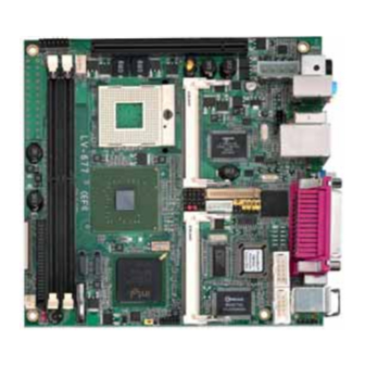
Page 14: Connector Location
LV-677 User’s Manual Chapter 2 <Hardware Setup> 2.1 <Connector Location> SYSFAN JFRNT CPUFAN SATA PCI-Express Mini-PCI DC-out COM Port DC-in (LV-677DC) Audio LPT Port USB&LAN IEEE1394 DC-in (LV-677DC) PS/2 HDTV S/PDIF... -
Page 15: Jumper Location & Reference
LV-677 User’s Manual Hardware Setup 2.2 <Jumper Location & Reference> Jumper Function JRTC CMOS Operating/Clear Setting JCFSEL CF with IDE mode selection JVLCD Panel Voltage Setting JRTC JCFSEL JVLCD Connector Location... -
Page 16: Connector Reference
Standard 44-pin IDE connector Slim 26-pin slim type floppy connector Slim S_ATA1/2 7-pin Serial ATA connector Standard PWRIN 24-pin power input connector (LV-677 only) Standard CN_BPWR 4-pin power output connector Standard CN_AUDIO 5 x 2-pin audio connector Standard CDIN 4-pin CD-ROM audio input connector... -
Page 17: Cpu And Memory Setup
LV-677 User’s Manual Hardware Setup 2.4 <CPU and Memory Setup> 2.4.1 <CPU Setup> The board comes with the socket479 for Intel Core Duo/Core Sole processors, it supports new generation of Intel Core Duo processors with 533/667MHz of front side bus and 2MB L2 cache. Please follow the instruction to install the CPU properly. -
Page 18: Memory Setup
LV-677 User’s Manual Hardware Setup 2.4.2 <Memory Setup> The board provides two 240-pin DDR2 DIMMs to support DDR2 400/533/667 memory modules up to 3GB of capacity. Non-ECC, unbuffered memory is supported only. While applying two same modules, dual channel technology is enabled automatically for higher performance. -
Page 19: Cmos Setup
LV-677 User’s Manual Hardware Setup 2.5 <CMOS Setup> The board’s data of CMOS can be setting in BIOS. If the board refuses to boot due to inappropriate CMOS settings, here is how to proceed to clear (reset) the CMOS to its default values. -
Page 20: Enhanced Ide Interface
LV-677 User’s Manual Hardware Setup 2.6 <Enhanced IDE Interface> The board has one UltraDMA33 IDE interface to support up to 2 ATAPI devices, and one CompactFlash Type II socket on the solder side, with jumper JCFSEL for IDE master/slave mode selection. -
Page 21: Floppy Port
LV-677 User’s Manual Hardware Setup 2.8 <Floppy Port> The board provides one slim type floppy port. Floppy rear side Lift up this plastic bar Slot the cable in (Blue paste for outside) Press back the plastic bar Lift up the brown plastic bar... -
Page 22: Ethernet Interface
LV-677 User’s Manual Hardware Setup 2.9 <Ethernet Interface> The board integrates with one Intel 82573L PCI Express Gigabit Ethernet controllers, as the PCI Express 1x can speed up to 250MB/s of transfer rate instead of late PCI bus with 133MB/s of transfer rate. The Intel 82573L supports triple speed of 10/100/1000Base-T, with IEEE802.3 compliance and Wake-On-LAN supported. -
Page 23: Onboard Display Interface
LV-677 User’s Manual Hardware Setup 2.10 <Onboard Display Interface> Based on Intel 945GM chipset with built-in GMA (Graphic Media Accelerator) 950 graphics, the board provides one DB15 connector on real external I/O port, and one 40-pin LVDS interface with 5-pin LCD backlight inverter connector. The board provides dual display function with clone mode and extended desktop mode for CRT and LCD. -
Page 24: Digital Display
LV-677 User’s Manual Hardware Setup 2.10.2 <Digital Display> The board provides one 40-pin LVDS connector for 18/24-bit single/dual channel panels, supports up to 1600 x 1200 (UXGA) resolution, with one LCD backlight inverter connector and one jumper for panel voltage setting. - Page 25 LV-677 User’s Manual Hardware Setup Connector: CN_INV Connector: JVLCD Type: 5-pin LVDS Power Header Type: 3-pin Power select Header Description Description +12V VCC(5V) LCDVCC VCC3(3.3) ENABKL Connector: CN_LVDS Type: onboard 40-pin connector for LVDS connector Connector model: HIROSE DF13-40DP-1.25V Signal...
- Page 26 LCD Installation Guide: Preparing the LV-677, LCD panel and the backlight inverter. Please check the datasheet of the panel to see the voltage of the panel, and set the jumper JVLCD to +5V or +3.3V.
- Page 27 LV-677 User’s Manual Hardware Setup After setup the devices well, you need to select the LCD panel type in the BIOS. The panel type mapping is list below: BIOS panel type selection form (BIOS Version:1.3) 18-bit Single channel 24-bit Dual channel...
-
Page 28: Hdtv Interface
LV-677 User’s Manual Hardware Setup 2.10.3 <HDTV Interface> The board provides one Mini-Din 7pin support Composite, S-Video and Component . HDTV Onboard Display Interface... -
Page 29: Integrated Audio Interface
LV-677 User’s Manual Hardware Setup 2.11 <Integrated Audio Interface> The board integrates onboard audio interface with REALTEK ALC880 codec, with Intel next generation of audio standard as High Definition Audio, it offers more sound and other advantages than former AC97 audio compliance. - Page 30 LV-677 User’s Manual Hardware Setup Connector: CN_AUDIO Type: 10-pin (2 x 5) 1.27mm x 2.54mm-pitch header Description Description MIC_L Ground MIC_R AVCC Speaker_R MIC Detect SENSE Speaker_L Speaker Detect Connector: CDIN Type: 4-pin header (pitch = 2.54mm) Description CD – Left...
-
Page 31: Gpio Interface
LV-677 User’s Manual Hardware Setup 2.12 <GPIO Interface> The board provides a programmable 8-bit digital I/O interface; you can use this general purpose I/O port for system control like POS or KIOSK. Connector: CN_DIO Type: 12-pin (6 x 2) 1.27mm x 2.54mm-pitch header... -
Page 32: Power Supply
The board requires DC 12V input with 4-pin mini DIN connector on rear I/O panel (LV-677DC Only) the input voltage range is from 8V to 21V, or onboard 24-pin ATX2.0 (LV-677 only) , for the input current, please take a reference of the power consumption report on appendix. -
Page 33: Power Output
LV-677 User’s Manual Hardware Setup 2.13.2 <Power Output> The board provides one 4-pin AT connector for +5V/+12V output for powering your HDD, CDROM or other devices. Connector: CN_BPWR (LV-677DC only) Type: 4-pin P-type connector for +5V/+12V output Description Description Description... -
Page 34: Switch And Indicator
LV-677 User’s Manual Hardware Setup 2.14 <Switch and Indicator> The JFRNT provides front control panel of the board, such as power button, reset and beeper, etc. Please check well before you connecting the cables on the chassis. Connector: JFRNT Type: onboard 14-pin (2 x 7) 2.54-pitch header... -
Page 35: Chapter 3
LV-673 User’s Manual System Setup Chapter 3 <System Setup> 3.1 <Video Memory Setup> Based on Intel® 945GM chipset with GMA (Graphic Media Accelerator) 950, the board supports Intel® DVMT (Dynamic Video Memory Technology) 3.0, which would allow the video memory to be allocated up to 224MB. To support DVMT, you need to install the Intel GMA 950 Driver with supported OS. - Page 36 LV-673 User’s Manual System Setup Fixed + DVMT Memory Size: You can select the fixed amount and the DVMT amount at the same time for a guaranteed video memory and additional dynamic video memory, please check the table below for available setting. On-Chip Fixed DVMT...
-
Page 37: Chapter 4
LV-673 User’s Manual BIOS Setup Chapter 4 <BIOS Setup> The motherboard uses the Award BIOS for the system configuration. The Award BIOS in the single board computer is a customized version of the industrial standard BIOS for IBM PC AT-compatible computers. It supports Intel x86 and compatible CPU architecture based processors and computers. - Page 38 LV-677 User’s Manual (This Page is Left for Blank)
-
Page 39: Appendix A
LV-677 User’s Manual I/O Port Pin Assignment Appendix A <I/O Port Pin Assignment> A.1 <IDE Port> Connector: IDE1 Type: 44-pin (22 x 2) box header Description Description Reset Ground Ground Ground -IOW Ground -IOR Ground IORDY Ground DACK Ground IDEIRQ... -
Page 40: A.2
LV-677 User’s Manual I/O Port Pin Assignment A.2 <Serial ATA Port> Connector: SATA1/2 Type: 7-pin wafer connector GND RSATA_TXP1 RSATA_TXN1 GND RSATA_RXN1 RSATA_RXP1 GND GND GND A.3 <Floppy Port> Connector: FDD Type: 26-pin connector Description Description INDEX DSKCHG MTR0 DRVDE0... -
Page 41: A.5
LV-677 User’s Manual I/O Port Pin Assignment A.5 <Serial Port> Connector: COM1/2 Type: 9-pin D-sub male connector on bracket Description Description DCD- /485- SIN- /485+ SO- /422+ DTR- /422- Ground Connector : LPT Type :25-Pin D-Sub female Connector on bracket... -
Page 42: A.6
LV-677 User’s Manual I/O Port Pin Assignment A.6 <VGA Port> Connector: CRT Type: 15-pin D-sub female connector on bracket Description Description Description Ground GREEN Ground DDCDA BLUE Ground HSYNC VSYNC Ground Ground DDCCLK A.7 <LAN Port> Connector: RJ45 Type: RJ45 connector with LED on bracket... -
Page 43: Appendix B
LV-677 User’s Manual Flash BIOS Appendix B <Flash BIOS> B.1 <Flash Tool> The board is based on Award BIOS and can be updated easily by the BIOS auto flash tool. You can download the tool online at the address below: http://www.phoenix.com/en/home/... -
Page 44: Appendix C
LV-677 User’s Manual I/O Port Pin Assignment Appendix C <System Resources> C1.<I/O Port Address Map> VGA Port... - Page 45 LV-677 User’s Manual Flash BIOS Flash BIOS...
- Page 46 LV-677 User’s Manual I/O Port Pin Assignment C2.<Memory Address Map> VGA Port...
- Page 47 LV-677 User’s Manual Flash BIOS C3.<System IRQ & DMA Resources> DMA: IRQ: Flash BIOS...
- Page 48 LV-677 User’s Manual I/O Port Pin Assignment The GPIO’can be programmed with the MSDOS debug program using simple IN/OUT commands.The following lines show an example how to do this. GPIO0…..GPIO7 bit0……bit7 -o 2E 87 ;enter configuration -o 2E 87 -o 2E 29 -o 2E 40 ;enale GPIO function...
- Page 49 LV-677 User’s Manual Flash BIOS Appendix D <Programming Watchdog Timer > The watchdog timer makes the system auto-reset while it stops to work for a period. The integrated watchdog timer can be setup as system reset mode by program. Timeout Value Range...
- Page 50 LV-677 User’s Manual I/O Port Pin Assignment Appendix E <How to setting RS-422 & RS-485> JCSEL1 JCSEL1 JCSEL1 RS-485 RS-232 RS-422 JCSEL2 JCSEL2 JCSEL2 JCSEL1 JCSEL2 VGA Port...
-
Page 51: Contact Information
Taiwan Commate Computer Inc. Address 8F, No. 94, Sec. 1, Shin Tai Wu Rd., Shi Chih Taipei Hsien, Taiwan +886-2-26963909 +886-2-26963911 Website h ttp://www.commell.com.tw E-Mail i nfo@commell.com.tw (General Information) t ech@commell.com.tw (Technical Support) Commell is our trademark of industrial PC division Flash BIOS...
Need help?
Do you have a question about the LV-677 and is the answer not in the manual?
Questions and answers