Supermicro SSE-X3348T/R User Manual
1/10 and 10-gigabit layer 2/3 ethernet switches
Hide thumbs
Also See for SSE-X3348T/R:
- Selection manual (1 page) ,
- Reference manual (985 pages) ,
- Installation manual (74 pages)
Table of Contents
Advertisement
Quick Links
Download this manual
See also:
Reference Manual
Advertisement
Table of Contents

Subscribe to Our Youtube Channel
Related Manuals for Supermicro SSE-X3348T/R


Summary of Contents for Supermicro SSE-X3348T/R
- Page 1 1/10 and 10-Gigabit Layer 2/3 Ethernet Switches SSE-G24-TG4 SSE-G48-TG4 1/10-Gigabit Ethernet Switch 1/10-Gigabit Ethernet Switch SSE-X24S/R 10/40-Gigabit Ethernet Switch SSE-X3348S/R 10/40-Gigabit Ethernet Switch SSE-X3348T/R 10/40-Gigabit Ethernet Switch User’s Manual Revison 1.1b...
- Page 2 Please Note: For the most up-to-date version of this manual, please see our web site at www.supermicro.com. Super Micro Computer, Inc. (“Supermicro”) reserves the right to make changes to the product described in this manual at any time and without notice. This product, including software, if any, and documentation may not, in whole or in part, be copied, photocopied, reproduced, translated or reduced to any medium or machine without prior written consent.
-
Page 3: Table Of Contents
..................... 1-1 1-3 Product Checklist of Typical Components ........1-2 1-4 Features ....................1-3 1-5 Physical Characteristics ..............1-3 1-6 Contacting Supermicro ..............1-4 Chapter 2 Standardized Warning Statements ..... 2-1 2-1 About Standardized Warning Statements ........2-1 Warning Definition................... 2-1 Installation Instructions ................ - Page 4 4-2 SSE-G48-TG4 Ports and Indicators ..........4-2 4-3 SSE-X24S/R Ports and Indicators ..........4-3 4-4 SSE-X3348S/R Ports and Indicators ..........4-4 4-5 SSE-X3348T/R Ports and Indicators ..........4-5 4-6 Ports ....................4-7 RJ45 Compatible Port ................4-7 Combo Ports ................... 4-7 10-Gb/s Port Module Bays..............
- Page 5 Table of Contents TACACS+ Server Configuration............5-20 IP Authorized Manager ..............5-21 SSH Configuration ................5-22 SSLConfiguration ................5-23 Syslog ....................5-25 ACL ....................... 5-26 MAC Based ACL ................5-26 IP Standard ACL ................5-28 IP Extended ACL................5-29 WEB Settings..................5-31 SNMP....................
- Page 6 1/10 and 10-Gigabit Layer 2/3 Ethernet Switches User’s Manual 5-5 Layer 2 Management ..............5-64 Layer 2 Basic Settings ................5-65 Port Manager ..................5-66 Port Basic Settings................5-67 Port Monitoring................... 5-68 Storm Control/Rate Limiting ............... 5-69 VLAN..................... 5-70 VLAN Basic Settings ................5-71 Port Settings..................
- Page 7 Table of Contents Filters ....................5-102 Unicast Filters .................. 5-103 Multicast Filters ................5-104 Line Tracking..................5-105 Loop Protect..................5-106 5-6 Layer 3 Management ..............5-107 IP......................5-108 Vlan Interface ................... 5-108 IPv4 AddrConf.................. 5-109 IP Route ................... 5-110 LoopBack Basic Settings ..............5-111 IP V6 ....................
- Page 8 1/10 and 10-Gigabit Layer 2/3 Ethernet Switches User’s Manual OSPF Area Aggregation ..............5-135 External Aggregation................ 5-136 OSPF V3..................... 5-138 OSPFv3 Basic Settings..............5-138 Interface ................... 5-139 Area....................5-141 OSPF V3 External Aggregation ............5-142 BGP ....................5-143 BGP Basic Settings................5-144 BGP Peer Configuration..............
- Page 9 Table of Contents Basic Settings .................. 5-171 Interface Configuration..............5-172 Group Information ................5-173 Source Information................5-174 PIM...................... 5-175 Basic Settings .................. 5-175 Component..................5-176 Interfaces ..................5-177 Candidate RPs ................. 5-178 Threshold ..................5-179 Static RP ..................5-180 DVMRP ....................5-181 DVMRP Basic Settings ..............
- Page 10 1/10 and 10-Gigabit Layer 2/3 Ethernet Switches User’s Manual LA Neighbor Statistics ..............5-209 802.1X....................5-210 802.1X Session Statistics..............5-210 802.1X Supplicant Statistics............. 5-211 Mac Session Statistics ..............5-213 IP......................5-214 ARP Cache ..................5-214 ICMP Statistics ................. 5-215 IPv6..................... 5-216 IP V6 Interface Statistics ..............
- Page 11 Appendix A Rack Installation ............A-1 A-1 Overview ....................A-1 A-2 Unpacking the System ..............A-1 A-3 Preparing for Setup ................A-1 Choosing a Setup Location..............A-1 A-4 Warnings and Precautions! .............A-2 Rack Precautions..................A-2 General Precautions ................A-2 Lithium Battery Precaution..............A-2 Rack Mounting Considerations ...............A-3 Ambient Operating Temperature ............A-3 Reduced Airflow ...................A-3 Mechanical Loading ................A-3 Circuit Overloading................A-3...
- Page 12 1/10 and 10-Gigabit Layer 2/3 Ethernet Switches User’s Manual Notes...
-
Page 13: About This Manual
This manual is written for professional system integrators, Information Technology professionals, service personnel and technicians. It provides information for the installation and use of Supermicro's Layer 2/3 1/10 and 10-Gigabit Ethernet switches. Installation and maintenance should be performed by experienced professionals only. - Page 14 1/10 and 10-Gigabit Layer 2/3 Ethernet Switches User’s Manual Notes...
-
Page 15: Chapter 1 Introduction
Chapter 1 Introduction Introduction This document is designed to provide Supermicro Switch users with the information required to configure the basic functionalities on the switch through the Web graphical user interface (GUI). Supermicro Switch products can be configured through Web browsers like Internet Explorer or Mozilla Firefox. -
Page 16: Product Checklist Of Typical Components
The SSE-X24S and SSE-X24SR are fully self-contained; no additional modules are required. The SSE-X3348S and SSE-X3348SR are also fully self contained, as are the SSE-X3348T and SSE-X3348T/R. All of the 10G switches contain two redundant hot-swappable power supplies installed at the factory. The SSE-X24S, SSE-X3348S and SSE-X3348T have a “normal”... -
Page 17: Features
440 x 473 x 44 mm (17.3 x 18.62 x 1.73 inch) for the SSE-X3348S/R • Weight: 5.6 kg (12.4 lbs) SSE-G24-TG4, 6.2 kg (13.7 lbs) SSE-G48-TG4, 7.58 kg (16.7 lbs) SSE-X24S/R, 8.2 kg (18.1 lbs) SSE-X3348S/R, or 9.2 kg (20.3 lbs) SSE-X3348T/R... -
Page 18: Contacting Supermicro
Address: Super Micro Computer, Inc. 980 Rock Ave. San Jose, CA 95131 U.S.A. Tel: +1 (408) 503-8000 Fax: +1 (408) 503-8008 marketing@supermicro.com (General Information) Email: support@supermicro.com (Technical Support) Web Site: www.supermicro.com Europe Address: Super Micro Computer B.V. Het Sterrenbeeld 28, 5215 ML ‘s-Hertogenbosch, The Netherlands... -
Page 19: Chapter 2 Standardized Warning Statements
The following statements are industry standard warnings, provided to warn the user of situations which have the potential for bodily injury. Should you have questions or experience difficulty, contact Supermicro's Technical Support department for assistance. Only certified technicians should attempt to install or configure components. - Page 20 1/10 and 10-Gigabit Layer 2/3 Ethernet Switches User’s Manual Warnung WICHTIGE SICHERHEITSHINWEISE Dieses Warnsymbol bedeutet Gefahr. Sie befinden sich in einer Situation, die zu Verletzungen führen kann. Machen Sie sich vor der Arbeit mit Geräten mit den Gefahren elektrischer Schaltungen und den üblichen Verfahren zur Vorbeugung vor Unfällen vertraut.
-
Page 21: Installation Instructions
Chapter 2: Standardized Warning Statements BELANGRIJKE VEILIGHEIDSINSTRUCTIES Dit waarschuwings symbool betekent gevaar. U verkeert in een situatie die lichamelijk letsel kan veroorzaken. Voordat u aan enige apparatuur gaat werken, dient u zich bewust te zijn van de bij een elektrische installatie betrokken risico's en dient u op de hoogte te zijn van de standaard procedures om ongelukken te voorkomen. -
Page 22: Circuit Breaker
1/10 and 10-Gigabit Layer 2/3 Ethernet Switches User’s Manual Waarschuwing Raadpleeg de installatie-instructies voordat u het systeem op de voedingsbron aansluit. Circuit Breaker Warning! This product relies on the building's installation for short-circuit (overcurrent) protection. Ensure that the protective device is rated not greater than: 250 V, 20 A. -
Page 23: Power Disconnection Warning
Chapter 2: Standardized Warning Statements 20A, 250V Waarschuwing Dit product is afhankelijk van de kortsluitbeveiliging (overspanning) van uw electrische installatie. Controleer of het beveiligde aparaat niet groter gedimensioneerd is dan 220V, 20A. Power Disconnection Warning Warning! The system must be disconnected from all sources of power and the power cord removed from the power supply module(s) before accessing the chassis interior to install or remove system components. -
Page 24: Equipment Installation
1/10 and 10-Gigabit Layer 2/3 Ethernet Switches User’s Manual ¡Advertencia! El sistema debe ser disconnected de todas las fuentes de energía y del cable eléctrico quitado de los módulos de fuente de alimentación antes de tener acceso el interior del chasis para instalar o para quitar componentes de sistema. -
Page 25: Restricted Area
Chapter 2: Standardized Warning Statements Warnung Das Installieren, Ersetzen oder Bedienen dieser Ausrüstung sollte nur geschultem, qualifiziertem Personal gestattet werden. ¡Advertencia! Solamente el personal calificado debe instalar, reemplazar o utilizar este equipo. Attention Il est vivement recommandé de confier l'installation, le remplacement et la maintenance de ces équipements à... - Page 26 1/10 and 10-Gigabit Layer 2/3 Ethernet Switches User’s Manual Warnung Diese Einheit ist zur Installation in Bereichen mit beschränktem Zutritt vorgesehen. Der Zutritt zu derartigen Bereichen ist nur mit einem Spezialwerkzeug, Schloss und Schlüssel oder einer sonstigen Sicherheitsvorkehrung möglich. ¡Advertencia! Esta unidad ha sido diseñada para instalación en áreas de acceso restringido.
-
Page 27: Battery Handling
Chapter 2: Standardized Warning Statements Battery Handling Warning! There is the danger of explosion if the battery is replaced incorrectly. Replace the battery only with the same or equivalent type recommended by the manufacturer. Dispose of used batteries according to the manufacturer's instructions. 警告... -
Page 28: Redundant Power Supplies
1/10 and 10-Gigabit Layer 2/3 Ethernet Switches User’s Manual Waarschuwing Er is ontploffingsgevaar indien de batterij verkeerd vervangen wordt. Vervang de batterij slechts met hetzelfde of een equivalent type die door de fabrikant aanbevolen wordt. Gebruikte batterijen dienen overeenkomstig fabrieksvoorschriften afgevoerd te worden. Redundant Power Supplies Warning! This unit might have more than one power supply connection. -
Page 29: Backplane Voltage
Chapter 2: Standardized Warning Statements Waarschuwing Deze eenheid kan meer dan één stroomtoevoeraansluiting bevatten. Alle aansluitingen dienen verwijderd te worden om het apparaat stroomloos te maken Backplane Voltage Warning! Hazardous voltage or energy is present on the backplane when the system is operating. -
Page 30: Comply With Local And National Electrical Codes
1/10 and 10-Gigabit Layer 2/3 Ethernet Switches User’s Manual Waarschuwing Een gevaarlijke spanning of energie is aanwezig op de backplane wanneer het systeem in gebruik is. Voorzichtigheid is geboden tijdens het onderhoud. Comply with Local and National Electrical Codes Warning! Installation of the equipment must comply with local and national electrical codes. -
Page 31: Product Disposal
Chapter 2: Standardized Warning Statements Waarschuwing Bij installatie van de apparatuur moet worden voldaan aan de lokale en nationale elektriciteitsvoorschriften. Product Disposal Warning! Ultimate disposal of this product should be handled according to all national laws and regulations. 警告 本产品的废弃处理应根据所有国家的法律和规章进行。 警告... -
Page 32: Hot Swap Fan Warning
1/10 and 10-Gigabit Layer 2/3 Ethernet Switches User’s Manual Waarschuwing De uiteindelijke verwijdering van dit product dient te geschieden in overeenstemming met alle nationale wetten en reglementen. Hot Swap Fan Warning Warning! The fans might still be turning when you remove the fan assembly from the chassis. -
Page 33: Power Cable And Ac Adapter
Electrical Appliance and Material Safety Law prohibits the use of UL or CSA -certified cables (that have UL/CSA shown on the code) for any other electrical devices than products designated by Supermicro only. 警告... - Page 34 Fehlfunktion oder ein Brand entstehen. Elektrische Geräte und Material Safety Law verbietet die Verwendung von UL-oder CSA-zertifizierte Kabel, UL oder CSA auf der Code für alle anderen elektrischen Geräte als Produkte von Supermicro nur bezeichnet gezeigt haben.
- Page 35 Het gebruik van andere kabels en adapters kan leiden tot een storing of een brand. Elektrisch apparaat en veiligheidsinformatiebladen wet verbiedt het gebruik van UL of CSA gecertificeerde kabels die UL of CSA die op de code voor andere elektrische apparaten dan de producten die door Supermicro alleen. 2-17...
- Page 36 1/10 and 10-Gigabit Layer 2/3 Ethernet Switches User’s Manual Notes 2-18...
-
Page 37: Chapter 3 Installation And Setup
3. Install the mounting ears onto the side of the switch using a screwdriver. 4. Mount the switch into your rack assembly (see Appendix A for optional rail mounting of the SSE-X24S/R, SSE-X3348S/R or SSE-X3348T/R). Configuring the Switch Module A Layer 2/3 1/10 and 10-Gigabit Ethernet Switch module can be configured using two methods. -
Page 38: Command Line
1/10 and 10-Gigabit Layer 2/3 Ethernet Switches Command Line Configuring the switch can be done using a command line via telnet or by using the serial console interface. Accessing CLI through Telnet To access the command line via telnet, follow the below steps. 1. -
Page 39: Firmware
Chapter 3: Installation and Setup Firmware The firmware for Layer 2/3 1/10 and 10-Gigabit Ethernet switches resides on a chip on the PCB. The switch has internal flash memory in two areas to hold two firmware images. The flash area used for the normal firmware image is referred to as the normal area. The other flash area, referred to as the fallback area, is used to store the firmware image for fallback purpose in case of a failure to boot from the normal area. - Page 40 1/10 and 10-Gigabit Layer 2/3 Ethernet Switches Booting using a Fallback Firmware Image Use the procedure below to boot using a fallback firmware image. 1. Reboot the switch by power cycling the switch power. 2. During reboot, press any key when it displays the below text (as shown in Figure 3-1).
- Page 41 Chapter 3: Installation and Setup Use the "H" option to set hardware information by typing the character H. This will display the hardware information that can be changed as shown in Figure 3-2. Figure 3-2. Setting Hardware Information 4. To choose the boot from a fallback image, type the command: rflag=1 5.
-
Page 42: Firmware Failure Recovery Steps
1/10 and 10-Gigabit Layer 2/3 Ethernet Switches 3. Login to the Switch CLI either through Telnet or a serial console port. 4. Type the below command to upgrade the firmware in the normal area: firmware upgrade tftp://<ip-address>/<filename> flash:fallbackl Here <ip-address> is the IP address of the TFTP server and <filename> is the name of the firmware image file. - Page 43 Chapter 3: Installation and Setup For example tftpaddr=192.168.2.100 9. Configure the gateway address to reach the TFTP server using the following command if the TFTP server is in a different network: gateway=<gateway IP> For example gateway=192.168.2.100 10. Configure the firmware image file name using the following command: ramdiskname=<filename>...
- Page 44 1/10 and 10-Gigabit Layer 2/3 Ethernet Switches Notes...
-
Page 45: Chapter 4 Ports And Indicators
Chapter 4 Ports and Indicators This chapter covers the ports and LED indicators found on Layer 2/3 1/10 and 10-Gigabit Ethernet switches. SSE-G24-TG4 Ports and Indicators Figure 4-1. SSE-G24-TG4 Ports and Indicators Front View Rear View Table 4-1. SSE-G24-TG4 Switch Module Ports and Indicators Item Description RJ45 10/100/1000 Ethernet ports (24) -
Page 46: Sse-G48-Tg4 Ports And Indicators
1/10 and 10-Gigabit Layer 2/3 Ethernet Switches SSE-G48-TG4 Ports and Indicators Figure 4-2. SSE-G48-TG4 Ports and Indicators Front View Rear View Table 4-2. SSE-G24-TG4 Switch Module Ports and Indicators Item Description RJ45 10/100/1000 Ethernet ports (48) SFP Combo Ports (4) LEDs and Stacking Indicator ID 10-Gb/s Port Module Bays (2 bays for up to 4 ports for CX-4 or XFP) Serial Port... -
Page 47: Sse-X24S/R Ports And Indicators
Chapter 4: Ports and Indicators SSE-X24S/R Ports and Indicators Figure 4-3. SSE-X24S/R Ports and Indicators Table 4-3. SSE-X24S/R Switch Module Ports and Indicators Item Description System Status Indicator Fan Status Indicator Status Indicator – Power Supply 1 Status Indicator – Power Supply 2 1-Gbps port (Line or console) 10-Gbps Ethernet Ports –... -
Page 48: Sse-X3348S/R Ports And Indicators
1/10 and 10-Gigabit Layer 2/3 Ethernet Switches SSE-X3348S/R Ports and Indicators Figure 4-4. SSE-X3348S/R Ports and Indicators Table 4-4. SSE-X3348S/R Switch Module Ports and Indicators Item Description Status indicators for: System, Fan, Power Supply 1 and Power Supply 2 1-Gbps ports (Line or console) 10-Gbps Ethernet Ports - SFP+ connectors 40-Gbps Ethernet ports –... -
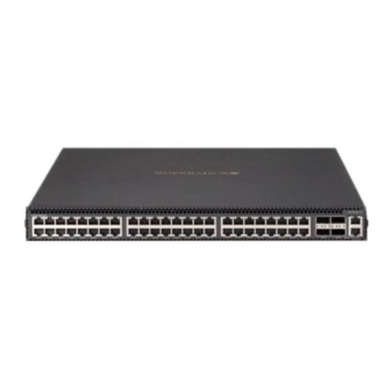
Page 49: Sse-X3348T/R Ports And Indicators
Chapter 4: Ports and Indicators SSE-X3348T/R Ports and Indicators Figure 4-5. SSE-X3348T/R Ports and Indicators Table 4-5. SSE-X3348T/R Switch Module Ports and Indicators Item Description Status indicators for: System, Fan, Power Supply 1 and Power Supply 2 1-Gbps ports (Line or console) 10-Gbps Ethernet Ports - RJ45 connectors 40-Gbps Ethernet ports –... - Page 50 1/10 and 10-Gigabit Layer 2/3 Ethernet Switches...
-
Page 51: Ports
Chapter 4: Ports and Indicators Ports Both Layer 2/3 1/10-Gigabit Ethernet switches contain several front mounted ports in common. RJ45 Compatible Port These 24 (SSE-G24-TG4) or 48 (SSE-G48-TG4) 1-Gb/s duplex ports each accept an RJ45 compatible cable. Combo Ports Each of the four SFP 1-Gb/s combo ports can hold a module for a downlinking fiber connector. -
Page 52: Serial Ports
AOM-SSE-X2C module with two CX4 copper interface ports for connections up to 12 meters in distance. NOTE: You must use a Supermicro CX4 cable if you are using one or more of these ports for stacking. You may use the Supermicro CBL-0474L for 1M connections or the CBL-0389L-01 for 3M connections. -
Page 53: Chapter 5 Web Based Management Utility
Port Number Ext */* – This is for an external port. Overview The Supermicro switch utility for Layer 2/3 1/10 and 10-Gigabit Ethernet switches provides a web-based interface for managing Layer 2 and Layer 3 switching at wire speed for constructing a switched/routed network. This interface provides both a bridging functionality and advanced features such as link aggregation, Dynamic VLAN/ Dynamic Multicast, IGMP Snooping and Network Access Control. -
Page 54: Login
IP. These switches will create VLAN 1 by default with this IP address, including all 1G and 10G ports. For the SSE-X24S/R, SSE-X3348S/R or SSE-X3348T/R switches you can connect to the 1G Ethernet RJ45 port, or the serial console port (on the front of the unit) to manage the switch. -
Page 55: Home Page
(Figure 5-2) contains links and menus for going to all other control pages in the Supermicro Switch web-based interface utility. A list of controls for this page is shown in Table 5-1. The basic page structure of the H page is duplicated for all subsequent sub-pages of the Supermicro Switch web-based interface utility. - Page 56 1/10 and 10-Gigabit Layer 2/3 Ethernet Switches User’s Manual Table 5-1. Home Page Controls and Components Number Name Description The Top Page Links are present both on the Home page and all other pages accessed and contain links to support pages or additional Top Page Links controls for all pages viewed with the Web Management Utility.
- Page 57 Chapter 5: Web Based Management Utility Figure 5-4. SSE-G48-TG4 Home Page Figure 5-5. SSE-X24S/R Home Page...
- Page 58 1/10 and 10-Gigabit Layer 2/3 Ethernet Switches User’s Manual Figure 5-6. SSE-X3348S/R Home Page Figure 6. SSE-X3348T/R Home Page...
-
Page 59: Top Page Links
• Support – Click this link to get technical support for Supermicro Products. • Help – Click on this link to open a context specific help page that covers all the items on the page being viewed. -
Page 60: Left Side Tree
1/10 and 10-Gigabit Layer 2/3 Ethernet Switches User’s Manual Left Side Tree The tree display on the left side of the page provides quick access to the configuration pages. This tree is organized based on the features supported in the switch. The main features are categorized in the following groups. -
Page 61: System Management Page
Chapter 5: Web Based Management Utility System Management Page Figure 5-1. System Management Page The S page (Figure 5-1) contains the following links: YSTEM ANAGEMENT • System Settings • Management IP • File Management • Firmware Upgrade • Management Security •... -
Page 62: System Settings
SNMP engine. A restart of the switch SNMP Engine ID required if these values are changed. The factory default is 80.00.08.1c.04.46.53 Assigns a contact person's name with a 255-character input limit. The Device Contact factory default is http://www.supermicro.com/support. 5-10... - Page 63 Description This specifies the location of this switch using a 255-characters input limit. Device Location The factory default is Supermicro. This specifies the maximum transmission unit (MTU) size of IP packets System MTU sent on an interface. The valid range is between 1500 and 9210, while the default value is 1500.
-
Page 64: System Version
1/10 and 10-Gigabit Layer 2/3 Ethernet Switches User’s Manual System Version Figure 5-3. System Version Page Clicking the S tab brings up the S page (Figure 5-3). This YSTEM ERSION YSTEM ERSION page provides a table that displays system version information including the switch ID, hardware version and firmware version for each switch. -
Page 65: Management Ip
Chapter 5: Web Based Management Utility Management IP Figure 5-4. Management IP Page Clicking the M IP tab brings up the M IP page (Figure 5-4). This ANAGEMENT ANAGEMENT page helps you to manage the IP address for the switch. This page allows to configure the following settings: •... -
Page 66: File Management
1/10 and 10-Gigabit Layer 2/3 Ethernet Switches User’s Manual File Management Figure 5-5. File Management Page Clicking the F link brings up the F page (Figure 5-5). ANAGEMENT ANAGEMENT The F page helps you to manage the configuration files in the switch. ANAGEMENT This page provides three main features. -
Page 67: File Copy
Chapter 5: Web Based Management Utility File Copy You can copy a local file to or from a remote TFTP server. This feature is useful to create a backup of configuration files remotely, and also to download configuration files from remote computers to the switch. -
Page 68: Management Security
1/10 and 10-Gigabit Layer 2/3 Ethernet Switches User’s Manual Management Security The M link provides configuration for the following features: ANAGEMENT ECURITY • Management Security Basic Settings • Management User Account • Radius • TACACS+ Global Settings • TACACS+ Server Configuration •... - Page 69 Chapter 5: Web Based Management Utility Table 5-3. Management Security Basic Settings Page Parameters Parameter Description The authentication modes supported are L , RADIUS and TACACS. The OCAL default option is "Local" mode where the user name and password is Authentication mode authenticated using a local user data base.
-
Page 70: Radius
1/10 and 10-Gigabit Layer 2/3 Ethernet Switches User’s Manual Radius Figure 5-9. Radius Server Configuration Page Clicking the R tab brings up the R page (Figure 5-9). ADIUS ADIUS ERVER ONFIGURATION This page allows you to configure the RADIUS server parameters as shown in Table 5-4. -
Page 71: Tacacs+ Global Settings
Chapter 5: Web Based Management Utility Table 5-4. RADIUS Server Configuration Page Parameters Parameter Description This parameter specifies the maximum time within which the Radius Server has Response Time to respond for a request from the Radius Client. The valid range is 0 to 120 (secs) seconds. -
Page 72: Tacacs+ Server Configuration
1/10 and 10-Gigabit Layer 2/3 Ethernet Switches User’s Manual TACACS+ Server Configuration Figure 5-11. TACACS+ Server Configuration Page Clicking the TACACS+ S tab brings up the TACACS+ S ERVERS ERVER ONFIGURATION page (Figure 5-11), which allows you to configure TACACS servers. The parameters for this page are shown in Table 5-6. -
Page 73: Ip Authorized Manager
Chapter 5: Web Based Management Utility IP Authorized Manager Figure 5-12. IP Authorized Manager Page Clicking the IP A tab brings up the IP A page ANAGER UTHORIZED ANAGER (Figure 5-12), which allows you to configure allowed management nodes for managing the switch. -
Page 74: Ssh Configuration
1/10 and 10-Gigabit Layer 2/3 Ethernet Switches User’s Manual SSH Configuration Figure 5-13. SSH Configuration Clicking the SSH (Secure Shell) tab brings up the SSH C page ONFIGURATION (Figure 5-13), which allows you to configure SSH version and keys. The parameters for this page are shown in Table 5-8. -
Page 75: Sslconfiguration
Chapter 5: Web Based Management Utility SSLConfiguration Figure 5-14. SSL Configuraiton Page Clicking the SSL (Secure Socket Layers) tab brings up the SSL C page ONFIGURATION (Figure 5-14), which allows you to configure SSL parameters and generate SSL certificates for HTTPS. To configure SSL and enable HTTPS, follow the procedure below using this page. - Page 76 1/10 and 10-Gigabit Layer 2/3 Ethernet Switches User’s Manual openssl x509 -req -in a.csr -out cert.pem -CA cacert.pem -CAkey cakey.pem -CAcreateserial The above steps will generate the certificate file cert.pem. 5. Open the generated certificate file cert.pem and delete the first line (---BEGIN CERTIFICATE ---) and last line (----END CERTIFICATE--).
-
Page 77: Syslog
Chapter 5: Web Based Management Utility Syslog Figure 5-15. Syslog Configuration Page Clicking the L tab brings up the S page (Figure 5-15), OGGING YSLOG ONFIGURATION which allows you to configure logging parameters. The parameters for this page are shown in Table 5-9. -
Page 78: Acl
1/10 and 10-Gigabit Layer 2/3 Ethernet Switches User’s Manual The ACL link allows you to configure the Access Control List for the switch. You can configure ACL on the following three pages: • MAC Based ACL • IP Standard ACL •... - Page 79 Chapter 5: Web Based Management Utility Table 5-10. MAC ACL Configuration Page Parameters (Continued) Parameter Description This specifies the action to be taken for the access list. The factory default is Permit. • Permit: Forwards packets which meet the ACL criteria. Action •...
- Page 80 1/10 and 10-Gigabit Layer 2/3 Ethernet Switches User’s Manual IP Standard ACL Figure 5-17. IP Standard ACL Configuration Page Clicking the IP S ACL (Access Control List) tab brings up the IP S TANDARD TANDARD page (Figure 5-17), which displays the various parameters to configure ONFIGURATION the Standard IP access lists.
- Page 81 Chapter 5: Web Based Management Utility IP Extended ACL Figure 5-18. IP Extended ACL Page Clicking the IP E ACL tab brings up the IP E ACL C page XTENDED XTENDED ONFIGURATION (Figure 5-18), which displays the various parameters required to configure the Extended IP access lists.
- Page 82 1/10 and 10-Gigabit Layer 2/3 Ethernet Switches User’s Manual Table 5-12. IP Extended ACL Configuration Page Parameters (Continued) Parameter Description This specifies the Message Code to be checked for ICMP Packets. The valid Message Code value is 255, which is also the factory default. This specifies the Message Type to be checked for ICMP Packets.
-
Page 83: Web Settings
Chapter 5: Web Based Management Utility WEB Settings Figure 5-19. Web GUI Settings Page Clicking the W link brings up the W GUI S page (Figure 5-19), ETTINGS ETTINGS which displays all basic Web GUI settings. The parameters for this page are shown in Table 5-13. -
Page 84: Snmp
1/10 and 10-Gigabit Layer 2/3 Ethernet Switches User’s Manual SNMP Figure 5-20. SNMP Agent Control Settings Page Clicking the SNMP link brings up the SNMP A page GENT ONTROL ETTINGS (Figure 5-20). SMIS supports the SNMP Agent or SNMP AgentX Sub-agent. The SNMP Agent or AgentX Sub-agent can be enabled or both can be disabled. - Page 85 Chapter 5: Web Based Management Utility Table 5-14. SNMP Agent Configuration Pages (Continued) Configuration Description Page This setting allows you to configure SNMP target parameters including SNMP Target , MP M and S ARAMETER ODEL ECURITY ODEL EVEL TORAGE Parameter Settings This setting allows you to configure SNMP security including user name, SNMP User Settings UTHENTICATION...
-
Page 86: Snmp Community Settings
1/10 and 10-Gigabit Layer 2/3 Ethernet Switches User’s Manual SNMP Community Settings Figure 5-21. SNMP Community Settings Page Clicking the C tab brings up the SNMP C page OMMUNITY OMMUNITY ETTINGS (Figure 5-21), which allows you to add SNMP managers or remove existing managers.. The parameters for this page are shown in Table 5-15. -
Page 87: Snmp Group Settings
Chapter 5: Web Based Management Utility SNMP Group Settings Figure 5-22. SNMP Group Settings Page Clicking the G tab brings up the SNMP G page (Figure 5-22). This ROUP ROUP ETTINGS page helps you map a combination of the S and the S into ECURITY... -
Page 88: Snmp Group Access Settings
1/10 and 10-Gigabit Layer 2/3 Ethernet Switches User’s Manual SNMP Group Access Settings Figure 5-23. SNMP Group Access Settings Page Clicking the G tab brings up the SNMP G page ROUP CCESS ROUP CCESS ETTINGS (Figure 5-23), which displays the access rights of groups. Each entry is indexed by a , a Context Prefix, a S and a S . -
Page 89: Snmp View Tree Settings
Chapter 5: Web Based Management Utility Table 5-17. SNMP Group Access Settings Page Parameters (Continued) Parameter Description Notify View This parameter allows you to specify the N identifier. OTIFY Use this parameter to specify whether the S is volatile or TORAGE Storage Type non-volatile. -
Page 90: Snmp Target Address Settings
1/10 and 10-Gigabit Layer 2/3 Ethernet Switches User’s Manual Table 5-18. SNMP View Tree Settings Page Parameters (Continued) Parameter Description View Type This parameter specifies whether a V is Included or Excluded. Use this parameter to specify whether the S is volatile or TORAGE Storage Type... -
Page 91: Snmp Target Parameter Settings
Chapter 5: Web Based Management Utility Table 5-19. SNMP Target Address Settings Page Parameters (Continued) Parameter Description contains SNMP parameters to be used when generating messages to be ARAM Param sent to a transport address. Use this parameter to specify whether the S is volatile or TORAGE Storage Type... -
Page 92: Snmp User Settings
1/10 and 10-Gigabit Layer 2/3 Ethernet Switches User’s Manual Table 5-20. SNMP Target Parameter Settings Page Parameters (Continued) Parameter Description specifies the level of security used when generating SNMP ECURITY EVEL Security Level messages. Storage Type can be configured as Volatile or Non-Volatile. TORAGE SNMP User Settings Figure 5-27. -
Page 93: Snmp Trap Settings
Chapter 5: Web Based Management Utility Table 5-21. SNMP Security Settings Page Parameters (Continued) Parameter Description is an indication of whether or not messages sent on behalf of this RIVACY Privacy Key user to/from the SNMP are protected from disclosure. Storage Type can be configured as Volatile or Non-Volatile. -
Page 94: Snmp Agentx
1/10 and 10-Gigabit Layer 2/3 Ethernet Switches User’s Manual SNMP AgentX Figure 5-29. SNMP AgentX Subagent Settings Page Clicking the A X link brings up the SNMP A page GENT GENT UBAGENT ETTINGS (Figure 5-29), which allows you to configure SNMP Agentx sub-agent parameters. The parameters for this page are shown in Table 5-23. -
Page 95: Rmon
Chapter 5: Web Based Management Utility RMON The following pages can be used to set RMON (Remote Monitoring) features and settings: • RMON Basic Settings • Event Configuration • RMON Alarm Configuration • Ethernet Statistics Configuration • History Control Configuration RMON Basic Settings Figure 5-30. -
Page 96: Event Configuration
1/10 and 10-Gigabit Layer 2/3 Ethernet Switches User’s Manual Event Configuration Figure 5-31. Event Configuration Settings Page Clicking the E tab brings up the E page (Figure 5-31), which VENTS VENT ONFIGURATIONS configures RMON events. The parameters for this page are shown in Table 5-24. -
Page 97: Rmon Alarm Configuration
Chapter 5: Web Based Management Utility RMON Alarm Configuration Figure 5-32. RMON Alarm Configuration Page Clicking the A tab brings up the RMON A page (Figure 5-32), LARM LARM ONFIGURATION which configures RMON Alarm paramters. The parameters for this page are shown in Table 5-25. -
Page 98: Ethernet Statistics Configuration
1/10 and 10-Gigabit Layer 2/3 Ethernet Switches User’s Manual Ethernet Statistics Configuration Figure 5-33. Ethernet Statistics Configuration Page Clicking the E tab brings up the E THERNET TATISTICS THERNET TATISTICS page (Figure 5-33), which configures RMON Ethernet statistics ONFIGURATION parameters. The parameters for this page are shown in Table 5-26. -
Page 99: History Control Configuration
Chapter 5: Web Based Management Utility History Control Configuration Figure 5-34. History Control Configuration Page Clicking the H tab brings up the H page ISTORY ISTORY ONTROL ONFIGURATION (Figure 5-34), which configures RMON history configuration parameters. The parameters for this page are shown in Table 5-27. -
Page 100: Qos
1/10 and 10-Gigabit Layer 2/3 Ethernet Switches User’s Manual The QoS link of the System page opens the QoS Basic Settings page. This page allows you to configure QoS through following pages: • QOS Basic Settings • QOS Classmap Settings •... - Page 101 Chapter 5: Web Based Management Utility QOS Classmap Settings Figure 5-36. QOS Classmap Settings Page Clicking the C tab brings up the QOS C page (Figure 5-36), LASSMAP LASSMAP ETTINGS which is used to classify the stream of traffic. The parameters for this page are shown in Table 5-29.
- Page 102 1/10 and 10-Gigabit Layer 2/3 Ethernet Switches User’s Manual QOS Policymap Settings Figure 5-37. QOS Policymap Settings Page Clicking the P tab brings up the QOS P page (Figure 5-37), OLICYMAP OLICYMAP ETTINGS which is used to specify action for a specified classmap. The parameters for this page are shown in Table 5-30.
- Page 103 Chapter 5: Web Based Management Utility COS Queue Mapping Figure 5-38. COS Queue Mapping Page Clicking C (Class of Service) tab brings up the COS Q page UEUE APPING (Figure 5-38), which configures the Class Of Server (COS) Queue Mapping. The parameters for this page are shown in Table 5-31.
-
Page 104: Time Management
1/10 and 10-Gigabit Layer 2/3 Ethernet Switches User’s Manual Time Management The Time Management link of the System page opens the Time Management page. This page allows you to configure QoS through following pages: • NTP Settings • Clock Settings NTP Settings Figure 5-39. - Page 105 Chapter 5: Web Based Management Utility Table 5-32. NTP Settings Page Parameters (Continued) Parameter Description Server IP Address Use this parameter to enter the NTP server IP address. Choose the key from the configured list. These keys are configurable in this page in the NTP S section’s fields.
-
Page 106: Clock Settings
1/10 and 10-Gigabit Layer 2/3 Ethernet Switches User’s Manual Clock Settings Figure 5-40. Clock Settings Page Clicking the C link brings up the C page (Figure 5-40), LOCK ETTINGS LOCK ETTINGS which allows to configure the Time and Date in the switch. The parameters for this page are shown in Table 5-33. -
Page 107: Stack
MAC address is selected as the Master switch. Enabling Stacking By default, Supermicro switches act as stand-alone switches. This stand-alone default facilitates using 10G Ethernet ports as Extrement Ethernet ports for uplinks. When stacking is enabled the stacking ports are dedicated for stacking purposes. - Page 108 1/10 and 10-Gigabit Layer 2/3 Ethernet Switches User’s Manual NOTE: If you choose stacking using the stack command from a non-stacking case, and the configurations are already saved for restoring the switch, it will rename the configuration file by adding a suffix _nonstack and will not restore this file when the switch reboots with stacking enabled.
-
Page 109: Stack Configuration
Chapter 5: Web Based Management Utility NOTE: In a stack only one switch can be configured as master. Otherwise the slave switches will not allow you to configure anything except stacking disabled. To login to slave switches, use a login name as "stackuser" and password as "stack123". - Page 110 1/10 and 10-Gigabit Layer 2/3 Ethernet Switches User’s Manual Stack Configuration Figure 5-42. Stack Configuration Page Clicking the S tab brings up the S page TACK ETTINGS TACK ONFIGURATION (Figure 5-42), which configures the stacking feature. The parameters for this page are shown in Table 5-34.
- Page 111 Chapter 5: Web Based Management Utility Stack Details Figure 5-43. Stack Details Page Clicking the S tab brings up the S page (Figure 5-43), which TACK ETAILS TACK ETAILS displays stacking details. The parameters for this page are shown in Table 5-35.
- Page 112 1/10 and 10-Gigabit Layer 2/3 Ethernet Switches User’s Manual Table 5-35. Stack Details Page Parameters (Continued) Parameter Description This parameter is used to specify the MAC address of the Slave switch. This Stack MAC MAC address is used to communicate between stack member switches. Switch State This parameter is used to specify the current status of the Slave switch.
-
Page 113: Stack Counters
Chapter 5: Web Based Management Utility Stack Counters Figure 5-45. Stack Counter Details Page Clicking the S tab brings up the S page TACK OUNTERS TACK OUNTERS ETAILS (Figure 5-45), which displays statistics for stacking ports. The parameters for this page are shown in Table 5-37. -
Page 114: Cx4 Cable Length
HC counter is 64-bit. CX4 Cable Length Stacking is supported with Supermicro CX-4 cables only. The CX-4 cable used for stacking should be no more than 3-meters in length, because stacking internally runs at 12-Gbps and therefore requires a more robust signal than longer cable lengths might provide reliably. - Page 115 Chapter 5: Web Based Management Utility Figure 5-46. Configuring CX4 Cable Length This configuration is done on an individual port basis. Thus, you can use "short" for one port and "long" for the other port. Alternatively you might use both "short" or, if neither are for stacking, both can be "long"...
-
Page 116: Layer 2 Management
1/10 and 10-Gigabit Layer 2/3 Ethernet Switches User’s Manual Layer 2 Management Figure 5-47. Layer2 Management Page The L page (Figure 5-47) contains the following links for Layer2 AYER ANAGEMENT controls: • Layer 2 Basic Settings • Port Manager • VLAN •... -
Page 117: Layer 2 Basic Settings
Chapter 5: Web Based Management Utility Layer 2 Basic Settings Figure 5-48. MAC Address Table Settings Page Clicking the L link brings up the MAC A AYER ASIC TTINGS DDRESS ABLE ETTINGS page (Figure 5-48), which gives you the option to change MAC aging time. MAC address confirmation can be done with this time interval. -
Page 118: Port Manager
1/10 and 10-Gigabit Layer 2/3 Ethernet Switches User’s Manual Port Manager The P link has links to the following web pages: ANAGER • Port Basic Settings • Port Monitoring • Storm Control/Rate Limiting NOTE: In all port based configuration pages, the port number group links are provided on the top. - Page 119 Chapter 5: Web Based Management Utility Port Basic Settings Figure 5-49. Port Basic Settings Page Clicking the B tab brings up the P page (Figure 5-49), ASIC ETTINGS ASIC ETTINGS which allows you to configure port status and mode information. This page also helps configuring priority and MTU.
-
Page 120: Port Monitoring
1/10 and 10-Gigabit Layer 2/3 Ethernet Switches User’s Manual Port Monitoring Figure 5-50. Port Monitoring Page Clicking the P tab brings up the P page (Figure 5-50), ONITORING ONITORING which allows you to enable or disbale monitoring on port interface. The parameters for this page are shown in Table 5-39. -
Page 121: Storm Control/Rate Limiting
Chapter 5: Web Based Management Utility Storm Control/Rate Limiting Figure 5-51. Storm Control/Rate Limiting Page Clicking the S tab brings up the S TORM ONTROL IMITING TORM ONTROL page (Figure 5-51), which allows you to configure specific parameters of the IMITING port. -
Page 122: Vlan
1/10 and 10-Gigabit Layer 2/3 Ethernet Switches User’s Manual Table 5-40. Storm Control/Rate Limiting Page Parameters (Continued) Parameter Description Multicast Level This parameter allows you to specify the multicast packets per second. The following parameters are configurable for Egress Rate Limiting. Egress Port Rate This parameter allows you to specify the egress limit of packets per second. - Page 123 Chapter 5: Web Based Management Utility VLAN Basic Settings Figure 5-52. VLAN Basic Settings Page Clicking the B tab brings up the VLAN B page (Figure 5-52), ASIC ETTINGS ASIC ETTINGS which displays VLAN global configuration information. The parameters for this page are shown in Table 5-41.
- Page 124 1/10 and 10-Gigabit Layer 2/3 Ethernet Switches User’s Manual Table 5-41. VLAN Basic Settings Page Parameters (Continued) Parameter Description Maximum Supported This parameter specifies the maximum number of VLANs that this device can VLANs scale. Number of VLANs in This parameter specifies the active number of VLANs configured in the device. the System In addition, the B page provides the configuration3 of Bridge Mode...
- Page 125 Chapter 5: Web Based Management Utility Port Settings Figure 5-53. VLAN Port Settings Page Clicking the P tab brings up the VLAN P page (Figure 5-53), ETTINGS ETTINGS which is used to associate the VLAN ID to the port for Port based VLAN classification. While associating different ports to VLANs, you can also configure I NGRESS ILTERING...
-
Page 126: Static Vlan
1/10 and 10-Gigabit Layer 2/3 Ethernet Switches User’s Manual Static VLAN Figure 5-54. Static VLAN Configuration Page Clicking the S VLAN tab brings up the S VLAN C page TATIC TATIC ONFIGURATION (Figure 5-54), which allows you to configure the VLAN related information statically. Using the first table you can create new entries for uncreated VLANs. -
Page 127: Protocol Group
Chapter 5: Web Based Management Utility Protocol Group Figure 5-55. VLAN Protocol Group Settings Page Clicking the P tab brings up the VLAN P ROTOCOL ROUP ROTOCOL ROUP ETTINGS page (Figure 5-55), which is used to map Protocol Templates to Protocol Group Identifiers. -
Page 128: Port Protocol
1/10 and 10-Gigabit Layer 2/3 Ethernet Switches User’s Manual Port Protocol Figure 5-56. Port VLAN Protocol Settings Clicking the Port P tab brings up the P VLAN P page ROTOCOL ROTOCOL ETTINGS (Figure 5-56), which displays a table used for Port and Protocol based VLAN classification. -
Page 129: Mac Vlan
Chapter 5: Web Based Management Utility MAC VLAN Figure 5-57. MAC Based VLAN Settings Page Clicking the MAC VLAN tab brings up the MAC B VLAN page (Figure 5-57), which ASED allows to add the MAC Address and Vlan ID to VLANs system. The parameters for this page are shown in Table 5-42. -
Page 130: Wildcard
1/10 and 10-Gigabit Layer 2/3 Ethernet Switches User’s Manual Wildcard Figure 5-58. Wildcard Settings Page Clicking the W tab brings up the W page (Figure 5-58), which ILDCARD ILDCARD ETTINGS configures wildcard MAC addresses and ports for VLANs. The parameters for this page are shown in Table 5-43. -
Page 131: Switch Port Filtering Vlan
Chapter 5: Web Based Management Utility Switch Port Filtering VLAN Figure 5-59. Switch Port VLAN Filtering Page Clicking the S tab brings up the S WITCH ILTERING WITCH ILTERING page (Figure 5-59), which configures utility criteria for SwitchPort Vlan filtering. The parameters for this page are shown in Table 5-44. -
Page 132: Dynamic Vlan
1/10 and 10-Gigabit Layer 2/3 Ethernet Switches User’s Manual Dynamic Vlan The Dynamic VLAN link allows you to configure the Dynamic VLAN information. Dynamic VLAN configuration information has been provided in the following pages • Dynamic VLAN Global Configuration • Port Configuration •... -
Page 133: Port Configuration
Chapter 5: Web Based Management Utility Port Configuration Figure 5-61. Dynamic VLAN Port Configuration Page Clicking the P link brings up the D VLAN P ETTINGS YNAMIC ONFIGURATION page (Figure 5-61), which allows you to configure parameters for Dynamic VLAN ports. The parameters for this page are shown in Table 5-45. -
Page 134: Garp Timers
1/10 and 10-Gigabit Layer 2/3 Ethernet Switches User’s Manual GARP Timers Figure 5-62. Garp Timers Configuration Page Clicking the G tab brings up the G page IMERS IMERS ONFIGURATION (Figure 5-62), which displays the various parameters for changing Garp times. The parameters for this page are shown in Table 5-46. -
Page 135: Rstp
Chapter 5: Web Based Management Utility RSTP The RSTP link provides links to the following configuration pages: • RSTP Global Settings • RSTP Basic Settings • Port Settings • Port Status RSTP Global Settings Figure 5-63. Global Configuration Page Clicking the G tab brings up the G page LOBAL... - Page 136 1/10 and 10-Gigabit Layer 2/3 Ethernet Switches User’s Manual RSTP Basic Settings Figure 5-64. RSTP Configuration Page Clicking the B tab brings up the RSTP C page (Figure 5-64), ASIC ETTINGS ONFIGURATION which displays the various parameters for RSTP configuration. The parameters for this page are shown in Table 5-48.
- Page 137 Chapter 5: Web Based Management Utility Port Settings Figure 5-65. Port Status Configuration Page Clicking the P tab brings up the P page ETTINGS TATUS ONFIGURATION (Figure 5-65), which allows you to set the configuration per port related to RSTP. The parameters for this page are shown in Table 5-49.
-
Page 138: Port Status
1/10 and 10-Gigabit Layer 2/3 Ethernet Switches User’s Manual Table 5-49. Port Status Configuration Page Parameters (Continued) Parameter Description Restricted Role This parameter specifies the RESTRICTED ROLE status of the port. Restricted TCN This parameter indicates the RESTRICTED TCN status of the port. Port Status Figure 5-66. -
Page 139: Mstp
Chapter 5: Web Based Management Utility Table 5-50. RSTP Port Status Page Parameters (Continued) Parameter Description This parameter specifies the operational point-to-point status of the LAN Type segment attached to this port. It indicates whether a port is considered to have a Point-to-point connection or Shared Media. - Page 140 1/10 and 10-Gigabit Layer 2/3 Ethernet Switches User’s Manual Clicking the B tab brings up the G page ASIC ETTINGS LOBAL ONFIGURATION (Figure 5-67), which can access the MSTP global configuration. The parameters for this page are shown in Table 5-51.
-
Page 141: Mstp Timers
Chapter 5: Web Based Management Utility MSTP Timers Figure 5-68. Timers Configuration Page Clicking the T tab brings up the T page (Figure 5-68), which IMERS IMERS ONFIGURATION configures the time for M AXIMUM OUNT ORWARD ELAY AXIMUM RANSMIT and H ELLO 5-89... -
Page 142: Port Configuration
1/10 and 10-Gigabit Layer 2/3 Ethernet Switches User’s Manual Port Configuration Figure 5-69. CIST Settings Page Clicking the P tab brings up the CIST S page (Figure 5-69), ONFIGURATION ETTINGS which sets the configuration per Port related to MSTP. The parameters for this page are shown in Table 5-52. -
Page 143: Vlan Mapping
Chapter 5: Web Based Management Utility Table 5-52. CIST Settings Page Parameters (Continued) Parameter Description Restricted Role This parameter specifies the Restricted role status of the port. Restricted TCN This parameter indicates the Restricted TCN status of the port. VLAN Mapping Figure 5-70. -
Page 144: Port Settings
1/10 and 10-Gigabit Layer 2/3 Ethernet Switches User’s Manual Port Settings Figure 5-71. Port Settings Page Clicking the P tab brings up the P page (Figure 5-71), which ETTINGS ETTINGS displays the various parameters for port settings. The parameters for this page are shown in Table 5-54. -
Page 145: Cist Port Status
Chapter 5: Web Based Management Utility CIST Port Status Figure 5-72. MSTP CIST Port Status Page Clicking the CIST P tab brings up the MSTP CIST P page TATUS TATUS (Figure 5-72), which displays MSTP CIST port specific information. The parameters for this page are shown in Table 5-55. -
Page 146: Link Aggregation (La)
Port Channel. Supermicro switches support both static link aggregation and dynamic link aggregation using IEEE 802.3ad and LACP. Up to 24 Port Channels can be configured on an individual switch and each Port Channel can contain up to 8 members. -
Page 147: La Basic Settings
Chapter 5: Web Based Management Utility LA Basic Settings Figure 5-73. LA Basic Settings Page Clicking the tab brings up the LA B page (Figure 5-73), BASIC ETTINGS ASIC ETTINGS which displays the various parameters for LA basic settings. The parameters for this page are shown in Table 5-56. -
Page 148: Interface Settings
1/10 and 10-Gigabit Layer 2/3 Ethernet Switches User’s Manual Table 5-56. LA Basic Settings Page Parameters Parameter Description LA Status This is used to enable or disable LA in the switch. System Priority This parameter specifies the priority value associated with the Actor's system ID. This parameter specifies the Bridge MAC Address that is displayed. -
Page 149: Port Settings
Chapter 5: Web Based Management Utility Port Settings Figure 5-75. LA Port Settings Page Clicking the P tab brings up the LA P page (Figure 5-75), ETTINGS ETTINGS which configures LA properties at a per-port level. The parameters for this page are shown in Table 5-58. -
Page 150: Basic Settings
1/10 and 10-Gigabit Layer 2/3 Ethernet Switches User’s Manual 802.1x The 802.1x link provides link to the following configuration pages: • Basic Settings • Port Settings • Timers • Local AS Basic Settings Figure 5-76. 802.1x Basic Settings Page Clicking the B tab brings up the 802.1 page ASIC... -
Page 151: Port Settings
Chapter 5: Web Based Management Utility Port Settings Figure 5-77. 802.1x Port Settings Page Clicking the P tab brings up the 802.1 page ETTINGS ETTINGS (Figure 5-77), which configures security information at the individual port levels. The parameters for this page are shown in Table 5-60. -
Page 152: Timers
1/10 and 10-Gigabit Layer 2/3 Ethernet Switches User’s Manual Table 5-60. 802.1x Port Settings Page Parameters (Continued) Parameter Description This parameter specifies the initialization control for the port. Setting this value to Port Initialize True causes the port to be initialized. The value reverts to False once initialization is complete. -
Page 153: Local As
Chapter 5: Web Based Management Utility Table 5-61. 802.1x Timer Configuration Page Parameters (Continued) Parameter Description This parameter specifies the time period used by the Authenticator State Transmit Period machine to define when the EAPOL PDU is to be transmitted. It can be (Seconds) configured to any value in the range from 1 to 65535 seconds. -
Page 154: Filters
1/10 and 10-Gigabit Layer 2/3 Ethernet Switches User’s Manual Table 5-62. Local Authentication Server Configuration Page Parameters (Continued) Parameter Description This parameter represents the allowance and denial of access. The values that can be configured are: • Allow - When set to Allow, the authentication request is allowed over the set Permission of ports in the P •... - Page 155 Chapter 5: Web Based Management Utility Unicast Filters Figure 5-80. L2 Unicast Filter Configuration Page Clicking the U tab brings up the L2 U page NICAST ILTERS NICAST ILTER ONFIGURATION (Figure 5-16), which sets the filter configuration to control the unicast packets that the switch needs to process.
- Page 156 1/10 and 10-Gigabit Layer 2/3 Ethernet Switches User’s Manual Multicast Filters Figure 5-81. L2 Multicast Filter Configuration Page Clicking the M tab brings up the L2 M ULTICAST ILTERS ULTICAST ILTER ONFIGURATION page (Figure 5-16), which allows you to set the filter configuration to control the multicast packets that the switch needs to process.
-
Page 157: Line Tracking
Chapter 5: Web Based Management Utility Line Tracking Figure 5-82. Link Status Tracking/Configure New Group Page Clicking the L link brings up the L RACKING TATUS RACKING ONFIGURE page (Figure 5-82), which allows you to set the filter configuration to control the ROUP multicast packets that the switch needs to process. -
Page 158: Loop Protect
1/10 and 10-Gigabit Layer 2/3 Ethernet Switches User’s Manual Loop Protect Figure 5-83. Loop Protection Page Clicking the L link brings up the L page (Figure 5-83), ROTECT ROTECTION which allows you to set the filter configuration to control the multicast packets that the switch needs to process. -
Page 159: Layer 3 Management
Chapter 5: Web Based Management Utility Layer 3 Management Figure 5-84. Layer3 Management Page The L home page (Figure 5-84) has the following links to all Layer 3 AYER ANAGEMENT features: • • IP V6 • DHCP Server • DHCP Relay •... -
Page 160: Vlan Interface
1/10 and 10-Gigabit Layer 2/3 Ethernet Switches User’s Manual The IP link enables you to perform IP related configuration. This can be done through the following pages. • Vlan Interface • IPv4 AddrConf • IP Route • LoopBack Basic Settings Vlan Interface Figure 5-85. -
Page 161: Ipv4 Addrconf
Chapter 5: Web Based Management Utility Table 5-68. VLAN Interface Basic Settings Page Parameters (Continued) Parameter Description Oper State Description IPv4 AddrConf Figure 5-86. IPv4 Address Configuration Page Clicking the IP tab brings up the IP page DDRESS ONFIGURATION (Figure 5-86), which allowsyou to configure the IP address for L3 VLANs. -
Page 162: Ip Route
1/10 and 10-Gigabit Layer 2/3 Ethernet Switches User’s Manual IP Route Figure 5-87. IP Route Configuration Page Clicking the IP R tab brings up the IP R page (Figure 5-87), OUTE OUTE ONFIGURATION which allows you to configure the static IP routes. The parameters for this page are shown in Table 5-70. -
Page 163: Loopback Basic Settings
Chapter 5: Web Based Management Utility LoopBack Basic Settings Figure 5-88. LoopBack Basic Settings Page Clicking the L tab brings up the L page ETTINGS ASIC ETTINGS (Figure 5-88), which allows you to configure loopback IP interfaces. The parameters for this page are shown in Table 5-71. -
Page 164: Ip V6
1/10 and 10-Gigabit Layer 2/3 Ethernet Switches User’s Manual IP V6 The IP 6 link allows you to perform IPv6 related configurations. This can be accomplished through the following six pages. • IPv6 Route Configuration • IPv6 Interface • ND Cache •... -
Page 165: Ipv6 Interface
Chapter 5: Web Based Management Utility Table 5-72. IP6 Route Configuration Page Parameters (Continued) Parameter Description Gateway This parameter specifies the Next Hop Gateway to reach the IP address. Interface This parameter indicates the outgoing interface. Distance (Metric) This parameter denotes metric value of the destination. IPv6 Interface Figure 5-90. -
Page 166: Nd Cache
1/10 and 10-Gigabit Layer 2/3 Ethernet Switches User’s Manual Table 5-73. IPv6 Interface Settings Page Parameters (Continued) Parameter Description This parameter indicates the Reachable time to be placed in the Router RA Rch Time Advertisements sent on the interface. This parameter specifies the RA Retransmit time to be placed in the Router RA Retrans Time Advertisement sent on the interface. -
Page 167: Address Settings
Chapter 5: Web Based Management Utility Table 5-74. ND Cache Configuration Page Parameters (Continued) Parameter Description This parameter indicates the Reachability state of the entry, which is a read-only State field. This parameter specifies the Age Time. Address Settings Figure 5-92. Address Settings Page Clicking the A tab brings up the A page... -
Page 168: Address Profile
1/10 and 10-Gigabit Layer 2/3 Ethernet Switches User’s Manual Address Profile Figure 5-93. Address Profile Settings Page Clicking the A tab brings up the A page DDRESS ROFILE DDRESS ROFILE ETTINGS (Figure 5-93). The parameters for this page are shown in Table 5-76. -
Page 169: Prefix Settings
Chapter 5: Web Based Management Utility Prefix Settings Figure 5-94. Prefix Configuration Page Clicking the P tab brings up the P page REFIX ETTINGS REFIX ONFIGURATION (Figure 5-94). The parameters for this page are shown in Table 5-77. Table 5-77. Prefix Configuration Page Parameters Parameter Description Interface VLAN ID... -
Page 170: Dhcp Server
1/10 and 10-Gigabit Layer 2/3 Ethernet Switches User’s Manual DHCP Server The DHCP Server link helps you to manage the DHCP server in the switch through the following two pages: • DHCP Basic Settings • Pool Settings DHCP Basic Settings Figure 5-95. -
Page 171: Pool Settings
Chapter 5: Web Based Management Utility Pool Settings Figure 5-96. DHCP Pool Settings Page Clicking the P link brings up the DHCP P page (Figure 5-96), ETTINS ETTINGS which allows you to configure the IP address pool that can be used by the DHCP server to allocate IP addresses. -
Page 172: Dhcp Relay
1/10 and 10-Gigabit Layer 2/3 Ethernet Switches User’s Manual DHCP Relay The DHCP Relay link helps you to manage the DHCP relay in the switch through the following two pages: • DHCP Relay Basic Settings • Interface Settings DHCP Relay Basic Settings Figure 5-97. -
Page 173: Interface Settings
Chapter 5: Web Based Management Utility Interface Settings Figure 5-98. DHCP Relay Interface Configuration Page Clicking the I tab brings up the DHCP R NTERFACE ELAY NTERFACE ONFIGURATION page (Figure 5-98), which allows you to configure the DHCP relay for VLANs. The parameters for this page are shown in Table 5-81. -
Page 174: Rip
1/10 and 10-Gigabit Layer 2/3 Ethernet Switches User’s Manual The RIP link opens the following links for configuration of RIP protocol: • RIP Basic Settings • Interfaces • Neighbors List • Security Settings • Address Summarization RIP Basic Settings Figure 5-99. RIP Basic Settings Page Clicking the B tab brings up the RIP B page... -
Page 175: Interfaces
Chapter 5: Web Based Management Utility Interfaces Figure 5-100. RIP Interface Page Clicking the I tab brings up the RIP I page (Figure 5-100). The NTERFACE NTERFACE parameters for this page are shown in Table 5-83. Table 5-83. RIP Interface Page Parameters Parameter Description Interface... -
Page 176: Neighbors List
1/10 and 10-Gigabit Layer 2/3 Ethernet Switches User’s Manual Neighbors List Figure 5-101. RIP Neighbor List Page Clicking the N tab brings up the RIP N page (Figure 5-101), which EIGHBORS EIGHBOR is used to configure the RIP neighbors, by configuring their IP address. The single parameter for this page is IP A , which specifies the IP Address of the DDRESS... -
Page 177: Security Settings
Chapter 5: Web Based Management Utility Security Settings Figure 5-102. RIP Security Settings Page Clicking the S tab brings up the RIP S page (Figure 5-102). The ECURITY ECURITY ETTING parameters for this page are shown in Table 5-12. Table 5-84. RIP Security Setting Page Parameters Parameter Description This parameter displays the active RIP interfaces. -
Page 178: Address Summarization
1/10 and 10-Gigabit Layer 2/3 Ethernet Switches User’s Manual Address Summarization Figure 5-103. RIP Interface Specific Address Summarization Page Clicking the S tab brings up the RIP I UMMARIZATION NTERFACE PECIFIC DDRESS page (Figure 5-103). The parameters for this page are shown in UMMARIZATION Table 5-85. -
Page 179: Rip6 Interface
Chapter 5: Web Based Management Utility RIP6 Interface Figure 5-104. RIP6 Interface Configuration Page Clicking the RIP6 I tab brings up the RIP6 I page NTERFACE NTERFACE ONFIGURATION (Figure 5-104). The parameters for this page are shown in Table 5-86. Table 5-86. -
Page 180: Filters
1/10 and 10-Gigabit Layer 2/3 Ethernet Switches User’s Manual Filters Figure 5-105. RIP6 Filter Configuration Page Clicking the F tab brings up the RIP6 F page (Figure 5-105). ILTERS ILTER ONFIGURATION The parameters for this page are shown in Table 5-87. - Page 181 Chapter 5: Web Based Management Utility OSPF Basic Settings Figure 5-106. OSPF Basic Settings Page Clicking the B tab brings up the OSPF B page ASIC ETTINGS ASIC ETTINGS (Figure 5-106). The parameters for this page are shown in Table 5-88.
-
Page 182: Area
1/10 and 10-Gigabit Layer 2/3 Ethernet Switches User’s Manual Area Figure 5-107. OSPF Area Configuration Page Clicking the A tab brings up the OSPF A page (Figure 5-107). ONFIGURATION The parameters for this page are shown in Table 5-89. Table 5-89. OSPF Area Configuration Page Parameters Parameter Description Area ID... -
Page 183: Interface
Chapter 5: Web Based Management Utility Interface Figure 5-108. OSPF Interface Configuration Page Clicking the I tab brings up the OSPF I page NTERFACE NTERFACE ONFIGURATION (Figure 5-108). The parameters for this page are shown in Table 5-90. Table 5-90. OSPF Interface Configuration Page Parameters Parameter Description Interface... -
Page 184: Virtual Interface
1/10 and 10-Gigabit Layer 2/3 Ethernet Switches User’s Manual Virtual Interface Figure 5-109. OSPF Virtual Interface Configuration Page Clicking the V tab brings up the OSPF V IRTUAL NTERFACE IRTUAL NTERFACE page (Figure 5-109). The parameters for this page are shown in ONFIGURATION Table 5-91. -
Page 185: Ospf Neighbor
Chapter 5: Web Based Management Utility OSPF Neighbor Figure 5-110. OSPF Neighbor Configuration Page Clicking the N tab brings up the OSPF N page EIGHBOR EIGHBOR ONFIGURATION (Figure 5-110), which allows you to configure OSPF neighbors. The parameters for this page are shown in Table 5-92. -
Page 186: Ospf Rrd Route Configuration
1/10 and 10-Gigabit Layer 2/3 Ethernet Switches User’s Manual OSPF RRD Route Configuration Figure 5-111. OSPF RRD Route Configuration Page Clicking the RRD R tab brings up the OSPF RRD R page OUTE OUTE ONFIGURATION (Figure 5-111), which displays the various parameters for RRD Route configuration. The parameters for this page are shown in Table 5-93. -
Page 187: Ospf Area Aggregation
Chapter 5: Web Based Management Utility OSPF Area Aggregation Figure 5-112. OSPF Area Aggregation Page Clicking the A tab brings up the OSPF A page GGREGATION GGREGATION (Figure 5-112). The parameters for this page are shown in Table 5-94. Table 5-94. OSPF Area Aggregation Page Parameters Parameter Description This parameter specifies the area associated with the OSPF address range. -
Page 188: External Aggregation
1/10 and 10-Gigabit Layer 2/3 Ethernet Switches User’s Manual External Aggregation Figure 5-113. OSPF As External Aggregation Configuration Page Clicking the E tab brings up the OSPF A GGREGATION XTERNAL GGREGATION page (Figure 5-113), which allows you to configure OSPF external ONFIGURATION aggregation parameters. - Page 189 Chapter 5: Web Based Management Utility Table 5-95. OSPF As External Aggregation Configuration Page Parameters Parameter Description This parameter specifies the Aggreation option as one of the following: • Advertise – When set to advertise and associated Area ID is 0.0.0.0, then the aggregated Type-5 are generated.
-
Page 190: Ospf V3
1/10 and 10-Gigabit Layer 2/3 Ethernet Switches User’s Manual OSPF V3 The OSPFv3 link allows you to configure the OSPFv3 protocol through the following pages: • OSPFv3 Basic Settings • Interface • Area • OSPF V3 External Aggregation OSPFv3 Basic Settings Figure 5-114. -
Page 191: Interface
Chapter 5: Web Based Management Utility Table 5-96. OSPFv3 Basic Settings Page Parameters (Continued) Parameter Description This parameter specifies maximum number of non-default AS-external-LSAs External LSDB Limit entries that can be stored in the link-state database. This parameter specifies the time interval in seconds a router will attempt to Exit Overflow Interval leave OverflowState. - Page 192 1/10 and 10-Gigabit Layer 2/3 Ethernet Switches User’s Manual Table 5-97. Interface Settings Page Parameters Parameter Description VLAN/Tunnel This parameter specifies the IPv6 interface over which OSPFv3 is enabled. Identifier Area ID This parameter specifies the area ID associated with the IPv6 interface. This parameter specifies the type of OSPFv3 interface (broadcast, nbma, Interface Type pointToPoint and pointToMultipoint).
-
Page 193: Area
Chapter 5: Web Based Management Utility Area Figure 5-116. OSPFv3 Area Settings Page Clicking the A tab brings up the OSPF page (Figure 5-116). The ETTINGS parameters for this page are shown in Table 5-98. Table 5-98. OSPFv3 Area Settings Page Parameters Parameter Description Area ID... -
Page 194: Ospf V3 External Aggregation
1/10 and 10-Gigabit Layer 2/3 Ethernet Switches User’s Manual OSPF V3 External Aggregation Figure 5-117. OSPF AS External Aggregation Configuration Page Clicking the E tab brings up the OSPF AS E GGREGATION XTERNAL GGREGATION page (Figure 5-117), which allows you to configure OSPF external ONFIGURATION aggregation parameters. -
Page 195: Bgp
Chapter 5: Web Based Management Utility Table 5-99. OSPF AS External Aggregation Configuration Page Parameters Parameter Description This parameter specifies the Aggreation option as one of the following: • Advertise – When set to advertise and the associated Area ID is 0.0.0.0, then aggregated Type-5 are generated. - Page 196 1/10 and 10-Gigabit Layer 2/3 Ethernet Switches User’s Manual BGP Basic Settings Figure 5-118. BGP Basic Settings Page Clicking the B tab brings up the BGP B page (Figure 5-118). The ASICS ASIC ETTINGS parameters for this page are shown in Table 5-100.
- Page 197 Chapter 5: Web Based Management Utility BGP Peer Configuration Figure 5-119. BGP Peer Configuration Page Clicking the N tab brings up the BGP P page EIGHBORS ONFIGURATION (Figure 5-119), which allows you to configre BGP Neighbors. The parameters for this page are shown in Table 5-101.
- Page 198 1/10 and 10-Gigabit Layer 2/3 Ethernet Switches User’s Manual BGP MED Configuration Figure 5-120. BGP MED Configuration Page Clicking the M tab brings up the BGP MED C page ULTI ONFIGURATION (Figure 5-120), which allows you to configure the MED value for routes learnt from BGP peers.
-
Page 199: Local Preference
Chapter 5: Web Based Management Utility Local Preference Figure 5-121. BGP Local Preference Configuration Page Clicking the L tab brings up the BGP L OCAL OCAL REFERENCE ONFIGURATION page (Figure 5-121), which allows you to configure the Local Preference value for routes. -
Page 200: Bgp Filter
1/10 and 10-Gigabit Layer 2/3 Ethernet Switches User’s Manual BGP Filter Figure 5-122. BGP Filter Configuration Page Clicking the F tab brings up the BGP F page (Figure 5-122), ILTERS ILTER ONFIGURATION which is used to set the filters on the routes being learnt. The parameters for this page are shown in Table 5-104. -
Page 201: Route Aggregations
Chapter 5: Web Based Management Utility Route Aggregations Figure 5-123. BGP Route Aggregation Configuration Page Clicking the R tab brings up the BGP R OUTE OUTE GGREGATION ONFIGURATION page (Figure 5-123), which is used to aggregate and configure the routes advertised by BGP. -
Page 202: Advanced Bgp Configuration
1/10 and 10-Gigabit Layer 2/3 Ethernet Switches User’s Manual Advanced BGP Configuration Figure 5-124. Advanced BGP Configuration Page Clicking the A tab brings up the A BGP C page DVANCED DVANCED ONFIGURATION (Figure 5-124), which configures dampening and confederation parameters. The parameters for this page are shown in Table 5-106. -
Page 203: Bgp Community Management
Chapter 5: Web Based Management Utility Table 5-106. Advanced BGP Configuration Page Parameters (Continued) Parameter Description Dampening Max This parameter specifies the maximum time (in seconds) a route can be Suppress Time suppressed. Dampening Decay This parameter specifies the time granularity in seconds used to perform all Granularity decay computations. - Page 204 1/10 and 10-Gigabit Layer 2/3 Ethernet Switches User’s Manual Table 5-107. BGP Community Management Page Parameters Parameter Description Community Route This parameter configures an entry in the Additive or Delete Community table. Configurations Community Filter This parameter configures the permit or deny function for the community Configurations attribute while receiving or advertising.
-
Page 205: Rrd
Chapter 5: Web Based Management Utility The RRD link allows you to manage the Route Redistribution with the help of the following pages: • RRD Basic Settings • • • OSPF RRD Basic Settings Figure 5-126. RRD Basic Settings Page Clicking the B tab brings up the RRD B page... -
Page 206: Bgp
1/10 and 10-Gigabit Layer 2/3 Ethernet Switches User’s Manual Figure 5-127. RRD BGP Configuration Page Clicking the BGP tab brings up the RRD BGP C page (Figure 5-127), ONFIGURATION which allows you to re-distribute the routes that are learnt through other routing protocols to BGP. -
Page 207: Rip
Chapter 5: Web Based Management Utility Figure 5-128. RRD RIP Configuration Page Clicking the RIP tab brings up the RRD RIP C page (Figure 5-128), which ONFIGURATION allows you to re-distribute the routes that are learnt through other routing protocols to RIP. -
Page 208: Ospf
1/10 and 10-Gigabit Layer 2/3 Ethernet Switches User’s Manual OSPF Figure 5-129. RRD OSPF Configuration Page Clicking the OSPF tab brings up the RRD OSPF C page (Figure 5-129), ONFIGURATION which allows you to e-distribute the routes that are learnt through other routing protocols to OSPF. -
Page 209: Rrd6
Chapter 5: Web Based Management Utility RRD6 The RRD6 link allows you to perform RRD6 related configuration through the following pages. • RRD6 Basic Settings • Filters • RRD V6 OSPF • RRD RIP RRD6 Basic Settings Figure 5-130. RRD6 Basic Settings Page Clicking the B tab brings up the RRD6 B page... -
Page 210: Filters
1/10 and 10-Gigabit Layer 2/3 Ethernet Switches User’s Manual Filters Figure 5-131. RRD6 Filter Configuration Page Clicking the F tab brings up the RRD6 F page ILTERS ILTER ONFIGURATION (Figure 5-131). The parameters for this page are shown in Table 5-112. -
Page 211: Rrd V6 Ospf
Chapter 5: Web Based Management Utility RRD V6 OSPF Figure 5-132. RRD6 OSPFv3 Configuration Page Clicking the OSPF 3 tab brings up the RRD6 OSPF page ONFIGURATION (Figure 5-132). The parameters for this page are shown in Table 5-113. Table 5-113. RRD6 OSPFv3 Configuration Page Parameters Parameter Description Status... -
Page 212: Rrd Rip
1/10 and 10-Gigabit Layer 2/3 Ethernet Switches User’s Manual RRD RIP Figure 5-133. RRD RIPv6 Configuration Page Clicking the RP6 tab brings up the RRD RIP page (Figure 5-133). ONFIGURATION The parameters for this page are shown in Table 5-114. Table 5-114. -
Page 213: Vrrp
Chapter 5: Web Based Management Utility VRRP The VRRP link allows you to configure VRRP through the following two pages: • VRRP Basic Settings • VRRP Settings VRRP Basic Settings Figure 5-134. VRRP Basic Settings Page Clicking the B tab brings up the VRRP B page ASIC ETTINGS... -
Page 214: Vrrp Settings
1/10 and 10-Gigabit Layer 2/3 Ethernet Switches User’s Manual VRRP Settings Figure 5-135. VRRP Settings Page Clicking the VRRP S link brings up the VRRP S page (Figure 5-135). ETTINGS ETTINGS The parameters for this page are shown in Table 5-115. -
Page 215: Multicast
Chapter 5: Web Based Management Utility Multicast Figure 5-136. Multicast Home Page page (Figure 5-136) has the following links to multicast features in the ULTICAST switch: • IGMP Snooping • Dynamic Multicast • IGMP • • DVMRP IGMP Snooping The IGMP Snooping link allows you to configure IGMP snooping through the following pages: •... - Page 216 1/10 and 10-Gigabit Layer 2/3 Ethernet Switches User’s Manual IGMP Snooping Configuration Figure 5-137. IGMP Snooping Configuration Page Clicking the B tab brings up the IGMP S page ASIC ETTINGS NOOPING ONFIGURATION (Figure 5-137), which allows you to configure IGMP snooping parameters. The parameters for this page are shown in Table 5-116.
- Page 217 Chapter 5: Web Based Management Utility IGMP Snooping Timer Figure 5-138. IGMP Snooping Timer Configuration Page Clicking the T tab brings up the IGMP S page IMER NOOPING IMER ONFIGURATION (Figure 5-138), which configures IGMP snooping timers. The parameters for this page are shown in Table 5-117.
- Page 218 1/10 and 10-Gigabit Layer 2/3 Ethernet Switches User’s Manual IGMP Snooping Interface Figure 5-139. IGMP Snooping Interface Configuration Page Clicking the tab brings up the IGMP S INTERFACE ONFIGURATION NOOPING NTERFACE page (Figure 5-139), which configures IGMP snooping interface specific ONFIGURATION parameters.
- Page 219 Chapter 5: Web Based Management Utility Table 5-118. IGMP Snooping Interface Configuration Page Parameters (Continued) Parameter Description Current Version This parameter specifies the working IGMP Version on the given VLAN. Current Querier This parameter specifies the current status of the Querier. Status IGMP Snooping VLAN Router Figure 5-140.
- Page 220 1/10 and 10-Gigabit Layer 2/3 Ethernet Switches User’s Manual IGMP MAC Forwarding Figure 5-141. MAC Based Multicast Forwarding Table Page Clicking the G tab brings up the MAC B ROUP NFORMATION ASED ULTICAST ORWARDING page (Figure 5-141), which displays either the IP Based or the MAC Based ABLE Multicast Forwarding Table depending upon the configuration of the forwarding mode.
-
Page 221: Dynamic Multicast
Chapter 5: Web Based Management Utility Dynamic Multicast The Dynamic Multicast link allows you to configure Dynamic Multicast through the following pages: • Global Configuration • Dynamic Multicast Port Configuration Global Configuration Figure 5-142. Dynamic Multicast Global Configuration Page Clicking the D tab brings up the D YNAMIC ULTICAST... - Page 222 1/10 and 10-Gigabit Layer 2/3 Ethernet Switches User’s Manual Dynamic Multicast Port Configuration Figure 5-143. Dynamic Multicast Port Configuration Page Clicking the P tab brings up the D ETTINGS YNAMIC ULTICAST ONFIGURATION page (Figure 5-143), which configures dynamic multicast at the port level. The parameters for this page are shown in Table 5-121.
-
Page 223: Igmp
Chapter 5: Web Based Management Utility IGMP The IGMP page allows you to configure the IGMP protocol. The IGMP protocol in the switch can be configured through the following pages: • Basic Settings • Interface Configuration • Group Information • Source Information Basic Settings Figure 5-144. - Page 224 1/10 and 10-Gigabit Layer 2/3 Ethernet Switches User’s Manual Interface Configuration Figure 5-145. IGMP Interface Configuration Page Clicking the I tab brings up the IGMP I NTERFACE ONFIGURATION NTERFACE page (Figure 5-145). The parameters for this page are shown in ONFIGURATION Table 5-122.
- Page 225 Chapter 5: Web Based Management Utility Group Information Figure 5-146. IGMP Group Configuration Page Clicking the G tab brings up the IGMP G page ROUP NFORMATION ROUP ONFIGURATION (Figure 5-146). The parameters for this page are shown in Table 5-123. Table 5-123.
- Page 226 1/10 and 10-Gigabit Layer 2/3 Ethernet Switches User’s Manual Source Information Figure 5-147. IGMP Source Information Page Clicking the S tab brings up the IGMP S page OURCE NFORMATION OURCE NFORMATION (Figure 5-147). The parameters for this page are shown in Table 5-124.
-
Page 227: Pim
Chapter 5: Web Based Management Utility The PIM link allows you to perform PIM related configuration through the following pages: • Basic Settings • Component • Interfaces • Candidate RPs • Threshold • Static RP Basic Settings Figure 5-148. PIM Basic Settings Page Clicking the B tab brings up the PIM B page... -
Page 228: Component
1/10 and 10-Gigabit Layer 2/3 Ethernet Switches User’s Manual Table 5-125. PIM Basic Settings Page Parameters (Continued) Parameter Description Registration Stop This parameter specifies the registration stop rate limiting period in seconds. Rate Limiting Period PMBR Status This parameter allows you to enable or disable the PMBR status in the switch. Static RP This parameter allows you to enable or disable the Static RP in the switch. -
Page 229: Interfaces
Chapter 5: Web Based Management Utility Interfaces Figure 5-150. PIM Interface Configuration Page Clicking the I tab brings up the PIM I page NTERFACES NTERFACE ONFIGURATION (Figure 5-150). The parameters for this page are shown in Table 5-127. Table 5-127. PIM Interface Configuration Page Parameters Parameter Description Interface... -
Page 230: Candidate Rps
1/10 and 10-Gigabit Layer 2/3 Ethernet Switches User’s Manual Candidate RPs Figure 5-151. Candidate RP Configuration Page Clicking the C tab brings up the C RP C page ANDIDATE ANDIDATE ONFIGURATION (Figure 5-151). The parameters for this page are shown in Table 5-128. -
Page 231: Threshold
Chapter 5: Web Based Management Utility Threshold Figure 5-152. PIM Threshold Configuration Page Clicking the T tab brings up the PIM T page HRESHOLD HRESHOLD ONFIGURATION (Figure 5-152). The parameters for this page are shown in Table 5-129. Table 5-129. PIM Threshold Configuration Page Parameters Parameter Description This parameter is a bits-per-second (BPS) value that when it exceeds a certain... -
Page 232: Static Rp
1/10 and 10-Gigabit Layer 2/3 Ethernet Switches User’s Manual Static RP Figure 5-153. Static RP Configuration Page Clicking the S RP tab brings up the S RP C page TATIC TATIC ONFIGURATION (Figure 5-153), which configure static PIM RPs (Rendezvous Points). The parameters for this page are shown in Table 5-130. -
Page 233: Dvmrp
Chapter 5: Web Based Management Utility DVMRP The DVMRP page allows you to configure the DVMRP protocol using the following pages: • DVMRP Basic Settings • Interfaces DVMRP Basic Settings Figure 5-154. DVMRP Basic Settings Page Clicking the B tab brings up the DVMRP B page ASIC ETTINGS... -
Page 234: Interfaces
1/10 and 10-Gigabit Layer 2/3 Ethernet Switches User’s Manual Interfaces Figure 5-155. DVMRP Interface Settings Page Clicking the I tab brings up the DVMRP I page NTERFACES NTERFACE ETTINGS (Figure 5-155), which displays the various parameters XXXXXX. The parameters for this page are shown in Table 5-132. -
Page 235: Statistics
Chapter 5: Web Based Management Utility Statistics Figure 5-156. Statistics Home Page The S page (Figure 5-156) contains links to all statistical information for TATISTICS all switch features and includes the following statistics pages: • Interface • Radius • TACACS+ Statistics •... -
Page 236: Interface
1/10 and 10-Gigabit Layer 2/3 Ethernet Switches User’s Manual • IGMP Statistics • • DVMRP Interface The Interface link allows you to configure the following pages: • Interface Statistics • Ethernet Statistics Interface Statistics Figure 5-157. Interface Statistics Page Clicking the I tab brings up the I page (Figure... - Page 237 Chapter 5: Web Based Management Utility Table 5-133. Interface Statistics Page Parameters (Continued) Parameter Description Received Unicast This parameter specifies the number of unicast packets received. Packets Received Nunicast This parameter specifies the number of non-unicast packets received. Packets Received Discards This parameter specifies the number of packets discared due to errors.
- Page 238 1/10 and 10-Gigabit Layer 2/3 Ethernet Switches User’s Manual Table 5-134. Ethernet Statistics Page Parameters Parameter Description Index This parameter specifies the port index. This parameter specifies the number of alignment errors. Alighment errors Alignment Errors generally indicate improper byte-alignment for Ethernet packets. FCS Errors This parameter specifies the number of packets received with checksum errors.
-
Page 239: Radius
Chapter 5: Web Based Management Utility Radius Figure 5-159. Radius Server Statistics Page Clicking the R link brings up the R page (Figure 5-159). ADIUS ADIUS ERVER TATISTICS The parameters for this page are shown in Table 5-135. Table 5-135. Radius Server Statistics Page Parameters Parameter Description Index... - Page 240 1/10 and 10-Gigabit Layer 2/3 Ethernet Switches User’s Manual Table 5-135. Radius Server Statistics Page Parameters (Continued) Parameter Description No of Malformed This parameter specifies the number of invalid access responses received. Access Responses No of Bad This parameter specifies the number of failed authentications. Authenticators No of Pending This parameter specifies the number of currently pending requests.
-
Page 241: Tacacs+ Statistics
Chapter 5: Web Based Management Utility TACACS+ Statistics Figure 5-160. TACACS+ Statistics Page Clicking the TACACS+ link brings up the TACACS+ S page (Figure 5-160). TATISTICS The parameters for this page are shown in Table 5-136. Table 5-136. TACACS+ Statistics Page Parameters Parameter Description Authentication Starts... - Page 242 1/10 and 10-Gigabit Layer 2/3 Ethernet Switches User’s Manual Table 5-136. TACACS+ Statistics Page Parameters (Continued) Parameter Description Authentication Get This parameter specifies the number of authentication get datas received. Data Received Authentication Errors This parameter specifies the number of authentication errors received. Received Authentication This parameter specifies the number of authentication follows received.
-
Page 243: Rmon Ethernet Statistics
Chapter 5: Web Based Management Utility RMON Ethernet Statistics Figure 5-161. RMON Ethernet Statistics Page Clicking the RMON link brings up the RMON E page (Figure 5-161), THERNET TATISTICS which displays RMON Ethernet statistics information. The parameters for this page are shown in Table 5-137. - Page 244 1/10 and 10-Gigabit Layer 2/3 Ethernet Switches User’s Manual Table 5-137. RMON Ethernet Statistics Page Parameters (Continued) Parameter Description This parameter specifies the number of Ethernet packets received with a size 64 Octets less than 64 bytes. This parameter specifies the number of Ethernet packets received with a size 65-127 Octets between 65 and 127 bytes.
-
Page 245: Snmp Statistics
Chapter 5: Web Based Management Utility SNMP Statistics The SNMP Statistics link allows you to configure SNMP Statistics through the following pages: • Agent • SNMP AgentX Agent Figure 5-162. SNMP Statistics Page Clicking the SNMP A link brings up the SNMP S page (Figure 5-162),... -
Page 246: Snmp Agentx
1/10 and 10-Gigabit Layer 2/3 Ethernet Switches User’s Manual Table 5-138. SNMP Statistics Page Parameters (Continued) Parameter Description SNMP Set Request This parameter specifies the number of SNMP Set Request PDU's. PDU's SNMP Packet Output This parameter specifies the number of SNMP packets output. SNMP Too Big Errors This parameter specifies the number of SNMP Too Big errors, SNMP No Such This parameter specifies the number of SNMP No Such Name errors,... -
Page 247: Vlan
Chapter 5: Web Based Management Utility Table 5-139. Agentx Subagent Statistics Page Parameters (Continued) Parameter Description IndexDeAlloc PDU This parameter specifies the number of IndexDeAlloc PDUs transmitted. UnRegister PDU This parameter specifies the number of unregister PDUs transmitted. Close PDU This parameter specifies the number of close PDUs transmitted. - Page 248 1/10 and 10-Gigabit Layer 2/3 Ethernet Switches User’s Manual Current DB Figure 5-163. VLAN Current Database Page Clicking the C DB tab brings up the VLAN C page URRENT URRENT ATABASE (Figure 5-163), which displays VLAN database entries. The parameters for this page are shown in Table 5-140.
- Page 249 Chapter 5: Web Based Management Utility VLAN Port Statistics Figure 5-164. VLAN Port Statistics Page Clicking the P tab brings up the VLAN P page TATISTICS TATISTICS (Figure 5-164), which displays the various parameters XXXXXX. The parameters for this page are shown in Table 5-141.
-
Page 250: Vlan Multicast Table
1/10 and 10-Gigabit Layer 2/3 Ethernet Switches User’s Manual VLAN Multicast Table Figure 5-165. VLAN Multicast Table Page Clicking the M tab brings up the VLAN M page ULTICAST ABLE ULTICAST ABLE (Figure 5-165), which displays multicast VLAN information. The parameters for this page are shown in Table 5-142. -
Page 251: Vlan Counter Statistics
Chapter 5: Web Based Management Utility VLAN Counter Statistics Figure 5-166. VLAN Counter Statistics Page Clicking the C link brings up the VLAN C page OUNTER TATISTICS OUNTER TATISTICS (Figure 5-166), which displays VLAN counters. The parameters for this page are shown Table 5-143. -
Page 252: Vlan Capabilities
1/10 and 10-Gigabit Layer 2/3 Ethernet Switches User’s Manual VLAN Capabilities Figure 5-167. VLAN Capabilities Page Clicking the C tab brings up the VLAN C page (Figure 5-167), APABILITIES APABILITIES which displays the VLAN capabilities of the switch. The parameters for this page are shown in Table 5-144. -
Page 253: Vlan Fdb Entries
Chapter 5: Web Based Management Utility VLAN FDB Entries Figure 5-168. VLAN FDB Entries Page Clicking the FDB E tab brings up the VLAN FDB E page (Figure 5-168), NTRIES NTRIES which displays VLAN filter database entries. The parameters for this page are shown in Table 5-145. - Page 254 1/10 and 10-Gigabit Layer 2/3 Ethernet Switches User’s Manual RSTP Information Figure 5-169. RSTP Information Page Clicking the I tab brings up the RSTP I page (Figure 5-169), NFORMATION NFORMATION which displays RSTP statistics. The parameters for this page are shown in Table 5-146.
- Page 255 Chapter 5: Web Based Management Utility RSTP Port Statistics Figure 5-170. RSTP Port Statistics Page Clicking the P tab brings up the RSTP P page TATISTICS TATISTICS (Figure 5-170), which displays RSTP port level statistics. The parameters for this page are shown in Table 5-147.
-
Page 256: Mstp Statistics
1/10 and 10-Gigabit Layer 2/3 Ethernet Switches User’s Manual Table 5-147. RSTP Port Statistics Page Parameters (Continued) Parameter Description Received Invalid This parameter specifies the number of invalid configuration BPDUs received. Configuration BPDUs Received Invalid TCN This parameter specifies the number of invalid topology change BPDUs BPDUs received. - Page 257 Chapter 5: Web Based Management Utility Table 5-148. MSTP Information Page Parameters Parameter Description Bridge Address This parameter specifies the Bridge Address. CIST Root This parameter specifies the CIST root. Regional Root This parameter specifies the Regional root. CIST Root Cost This parameter specifies the CIST root cost.
- Page 258 1/10 and 10-Gigabit Layer 2/3 Ethernet Switches User’s Manual Table 5-149. MSTP CIST Port Statistics Page Parameters Parameter Description Received MST This parameter specifies the number of MSTP BPDUs received. BPDUs Received RST This parameter specifies the number of RSTP BPDUs received. BPDUs Received Config This parameter specifies the number of config BPDUs received.
- Page 259 Chapter 5: Web Based Management Utility MSTP MSTI Port Statistics Figure 5-173. MSTP MSTI Port Statistics Page Clicking the MSTI P tab brings up the MSTP MSTI P page TATISTICS TATISTICS (Figure 5-173), which displays MSTP MSTI port level statistics. The parameters for this page are shown in Table 5-150.
-
Page 260: Link Aggregation (La)
1/10 and 10-Gigabit Layer 2/3 Ethernet Switches User’s Manual Link Aggregation (LA) The Link Aggregation link allows you to view Link Aggregation (LA) statistics through the following pages: • LA Port Statistics • LA Neighbor Statistics LA Port Statistics Figure 5-174. LA Port Statistics Page Clicking the P LACP S tab brings up the LA P... - Page 261 Chapter 5: Web Based Management Utility Table 5-151. LA Port Statistics Page Parameters (Continued) Parameter Description Received Illegal This parameter specifies the number of invalid PDUs received. PDUs Transmitted PDUs This parameter specifies the number of LACP PDUs transmitted. Transmitted Marker This parameter specifies the number of Marker PDUs transmitted.
-
Page 262: 802.1X Session Statistics
1/10 and 10-Gigabit Layer 2/3 Ethernet Switches User’s Manual 802.1X The 802.1x link allows you to view 802.1x statistics through the following pages: • 802.1X Session Statistics • 802.1X Supplicant Statistics • Mac Session Statistics 802.1X Session Statistics Figure 5-176. 802.1x Session Statistics Page Clicking the S tab brings up the 802.1 page... -
Page 263: X Supplicant Statistics
Chapter 5: Web Based Management Utility Table 5-153. 802.1x Session Statistics Page Parameters (Continued) Parameter Description Session Terminate This parameter specifies the reason for session termination. Cause User Name This parameter specifies the name of the user authenticated. 802.1X Supplicant Statistics Figure 5-177. - Page 264 1/10 and 10-Gigabit Layer 2/3 Ethernet Switches User’s Manual Table 5-154. 802.1x Supplicant Session Statistics Page Parameters (Continued) Parameter Description This parameter specifies the number of the EAPOL response packet frame Eapol Resp FrTx transmitted. This parameter specifies the number of the EAPOL request identifier packet Eapol ReqId FrRx received.
- Page 265 Chapter 5: Web Based Management Utility Mac Session Statistics Figure 5-178. MAC Session Statistics Page Clicking the M tab brings up the MAC S page ESSION TATS ESSION TATISTICS (Figure 5-178), which displays statistics information about 802.1x MAC sessions. The parameters for this page are shown in Table 5-155.
-
Page 266: Arp Cache
1/10 and 10-Gigabit Layer 2/3 Ethernet Switches User’s Manual The IP link allows you to view IP statistics through the following pages: • ARP Cache • ICMP Statistics ARP Cache Figure 5-179. ARP Cache Page Clicking the ARP C tab brings up the ARP C page (Figure 5-179), which... - Page 267 Chapter 5: Web Based Management Utility ICMP Statistics Figure 5-180. ICMP Statistics Page Clicking the ICMP S tab brings up the ICMP S page (Figure 5-180), TATISTICS TATISTICS which displays ICMP statistics information. The parameters for this page are shown in Table 5-157.
-
Page 268: Ipv6
1/10 and 10-Gigabit Layer 2/3 Ethernet Switches User’s Manual Table 5-157. ICMP Statistics Page Parameters (Continued) Parameter Description Transmitted Destination This parameter specifies the number of transmitted destination unreachables. Unreachable Transmitted Redirect This parameter specifies the number of transmitted redirects. Transmitted Echo This parameter specifies the number of transmitted echo requests. - Page 269 Chapter 5: Web Based Management Utility Table 5-158. IPV6 Interface Statistics Page Parameters Parameter Description Interface This parameter specifies the Port index. Rcvd This parameter specifies the number of IPv6 packets received. Hdr Err This parameter specifies the number of IPv6 packets received with header error. Too Big Errs This parameter specifies the number of too big IPv6 packets received.
- Page 270 1/10 and 10-Gigabit Layer 2/3 Ethernet Switches User’s Manual ICMP V6 Statistics Figure 5-182. ICMPv6 Statistics Page Clicking the ICMP 6 tab brings up the ICMP page (Figure 5-182), which TATISTICS displays ICMPv6 statistics. The parameters for this page are shown in Table 5-159.
- Page 271 Chapter 5: Web Based Management Utility Table 5-159. ICMPv6 Statistics Page Parameters (Continued) Parameter Description In Redirects This parameter specifies the number of redirect packets received. In Admin Prohib This parameter specifies the number of receive admin prohibted. Out Messages This parameter specifies the number of messages transmitted.
-
Page 272: Rip Statistics
1/10 and 10-Gigabit Layer 2/3 Ethernet Switches User’s Manual RIP Statistics Figure 5-183. RIP Interface Statistics Page Clicking the RIP link brings up the RIP I page (Figure 5-183), which NTERFACE TATISTICS displays RIP statistics. The parameters for this page are shown in Table 5-160. - Page 273 Chapter 5: Web Based Management Utility RIP6 Interface Statistics Figure 5-184. RIP6 Interface Statistics Page Clicking the I tab brings up the RIP6 I page NTERFACE TATISTICS NTERFACE TATISTICS (Figure 5-184), which displays RIPng statistics. The parameters for this page are shown Table 5-161.
-
Page 274: Ospf
1/10 and 10-Gigabit Layer 2/3 Ethernet Switches User’s Manual RIP6 Route Information Figure 5-185. RIP6 Route Information Page Clicking the R tab brings up the RIP6 R page OUTE NFORMATION OUTE NFORMATION (Figure 5-185), which displays information about RIPng routes. The parameters for this page are shown in Table 5-162. - Page 275 Chapter 5: Web Based Management Utility OSPF Route Information Figure 5-186. OSPF Route Information Page Clicking the R tab brings up the OSPF R page OUTE NFORMATION OUTE NFORMATION (Figure 5-186), which displays information about OSPF routes. The parameters for this page are shown in Table 5-163.
- Page 276 1/10 and 10-Gigabit Layer 2/3 Ethernet Switches User’s Manual OSPF Link State DB Figure 5-187. OSPF Link State Database Page Clicking the L tab brings up the OSPF L page TATE ATABASE TATE ATABASE (Figure 5-187), which displays information about OSPF link state database. The parameters for this page are shown in Table 5-164.
-
Page 277: Ospfv3
Chapter 5: Web Based Management Utility OSPFv3 The OSPFv3 link allows you to view OSPFv3 statistics through the following pages: • OSPFV3 Route Information • OSPFV3 Link State DB OSPFV3 Route Information Figure 5-188. OSPFV3 Route Information Page Clicking the OSPFV3 R tab brings up the OSPFV3 R OUTE NFORMATION... - Page 278 1/10 and 10-Gigabit Layer 2/3 Ethernet Switches User’s Manual OSPFV3 Link State DB Figure 5-189. OSPFV3 Link State Database Page Clicking the OSPFV3 L tab brings up the OSPFV3 L TATE ATABASE TATE page (Figure 5-189), which displays information about OSPF link state ATABASE database.
-
Page 279: Vrrp Statistics
Chapter 5: Web Based Management Utility VRRP Statistics Figure 5-190. VRRP Statistics Page Clicking the VRRP link brings up the VRRP S page (Figure 5-190), which TATISTICS displays VRRP global statistics and VRRP router specific statistics. The parameters for this page are shown in Table 5-167. - Page 280 1/10 and 10-Gigabit Layer 2/3 Ethernet Switches User’s Manual Table 5-167. VRRP Statistics Page Parameters (Continued) Parameter Description Priority Zero Packet This parameter specifies the number of priority zero packets received. Received Priority Zero Packet This parameter specifies the number of priority zero packets transmitted. Transmited Invalid Packet Type This parameter specifies the number of invalid packets received.
-
Page 281: Igmp Snooping
Chapter 5: Web Based Management Utility IGMP Snooping The IGMP link allows you to view IGMP statistics through the following pages: • IGMP Snooping Clear Statistics • IGMP Snooping V1/V2 Statistics • IGMP Snooping V3 Statistics IGMP Snooping Clear Statistics Figure 5-191. - Page 282 1/10 and 10-Gigabit Layer 2/3 Ethernet Switches User’s Manual IGMP Snooping V1/V2 Statistics Figure 5-192. IGMP Snooping V1/V2 Statistics Page Clicking the IGS S tab brings up the IGMP S V1/V2 S page TATISTICS NOOPING TATISTICS (Figure 5-192), which displays IGMP snooping statistics. The parameters for this page are shown in Table 5-169.
- Page 283 Chapter 5: Web Based Management Utility Table 5-169. IGMP Snooping V1/V2 Statistics Page Parameters (Continued) Parameter Description Group Queries This parameter specifies the number of group query packets transmitted. Transmitted IGMP Reports This parameter specifies the number of IGMP report packets transmitted. Transmitted IGMP Leaves This parameter specifies the number of IGMP leave packets transmitted.
-
Page 284: Igmp Statistics
1/10 and 10-Gigabit Layer 2/3 Ethernet Switches User’s Manual Table 5-170. IGMP Snooping V3 Statistics Page Parameters (Continued) Parameter Description TO_INCL Messages This parameter specifies the number of messages received with to include field. Received TO_EXCL Messages This parameter specifies the number of messages received with to exclude field. Received ALLOW Messages This parameter specifies the number of allow messages received. -
Page 285: Pim
Chapter 5: Web Based Management Utility Table 5-171. IGMP Route Statistics Page Parameters (Continued) Parameter Description Group Queries This parameter specifies the number of group query packets received. Received Group and Source This parameter specifies the number of group and source query packets Queries Received received. - Page 286 1/10 and 10-Gigabit Layer 2/3 Ethernet Switches User’s Manual PIM Interface Statistics Figure 5-195. PIM Interface Statistics Page Clicking the I tab brings up the PIM I page NTERFACE TATS NTERFACE TATISTICS (Figure 5-195), which displays PIM interface statistics. The parameters for this page are shown in Table 5-172.
- Page 287 Chapter 5: Web Based Management Utility PIM Neighbor Statistics Figure 5-196. PIM Neighbor Statistics Page Clicking the N tab brings up the PIM N page EIGHBOR TATS EIGHBOR TATISTICS (Figure 5-196), which displays PIM neighbor statistics. The parameters for this page are shown in Table 5-173.
- Page 288 1/10 and 10-Gigabit Layer 2/3 Ethernet Switches User’s Manual PIM BSR Info Figure 5-197. PIM BSR Info Page Clicking the BSR I tab brings up the PIM BSR I page (Figure 5-197). The parameters for this page are shown in Table 5-174.
- Page 289 Chapter 5: Web Based Management Utility PIM RP Set Information Figure 5-198. PIM RP Information Page Clicking the RP S tab brings up the PIM RP I page (Figure 5-198), NFORMATION which displays PIM RP information. The parameters for this page are shown in Table 5-175.
- Page 290 1/10 and 10-Gigabit Layer 2/3 Ethernet Switches User’s Manual PIM Route Information Figure 5-199. PIM Route Information Page Clicking the M tab brings up the PIM R page ROUTE OUTE NFORMATION (Figure 5-199), which displays PIM route information. The parameters for this page are shown in Table 5-176.
-
Page 291: Dvmrp
Chapter 5: Web Based Management Utility DVMRP The DVMRP link allows you to view DVMRP statistics through the following pages: • DVMRP Routers • DVMRP Multicast Routers • DVMRP Prune Statistics DVMRP Routers Figure 5-200. DVMRP Routes Page Clicking the R tab brings up the DVMRP R page (Figure... - Page 292 1/10 and 10-Gigabit Layer 2/3 Ethernet Switches User’s Manual DVMRP Multicast Routers Figure 5-201. DVMRP Multicast Routes Page Clicking the M tab brings up the DVMRP M page ULTICAST OUTES ULTICAST OUTES (Figure 5-201), which displays DVMRP multicast routes information. The parameters for this page are shown in Table 5-178.
- Page 293 Chapter 5: Web Based Management Utility DVMRP Prune Statistics Figure 5-202. DVMRP Prune Statistics Page Clicking the P tab brings up the DVMRP P page RUNE ORWARD RUNE TATISTICS (Figure 5-202), which DVMRP prune statistics information. The parameters for this page are shown in Table 5-179.
- Page 294 1/10 and 10-Gigabit Layer 2/3 Ethernet Switches User’s Manual Notes 5-242...
-
Page 295: Appendix A Rack Installation
Rack Installation Overview Some Supermicro switches can be equipped with an optional rail kit (CSE-PT52L) to make it easy to install them in a rack. This manual provides instructions for installing the CSE-PT52L mounting rails onto a rack and for installing the switch into the mounting rails. -
Page 296: Warnings And Precautions
1/10 and 10-Gigabit Layer 2/3 Ethernet Switches Warnings and Precautions! Rack Precautions • Ensure that the leveling jacks on the bottom of the rack are fully extended to the floor with the full weight of the rack resting on them. •... -
Page 297: Rack Mounting Considerations
Appendix A: Rack Installation • Please comply with the regulations set up by your local hazardous waste management agency to dispose of your used battery properly. Rack Mounting Considerations Ambient Operating Temperature If installed in a closed or multi-unit rack assembly, the ambient operating temperature of the rack environment may be greater than the ambient temperature of the room. -
Page 298: Identifying The Sections Of The Rack Rails
1/10 and 10-Gigabit Layer 2/3 Ethernet Switches NOTE: Your switch may differ from the illustrations in this manual. Identifying the Sections of the Rack Rails The CSE-PT52L rail kit package includes two rack rail assemblies in the rack mounting kit. Each assembly consists of two sections: a fixed inner rail that secures directly to the side of the switch, and a fixed outer rail that secures directly to the rack itself. -
Page 299: Installing The Inner Rails
Appendix A: Rack Installation Separating the Rails 1. Separate the inner rail from the outer rail by depressing the black plastic flange inside the inner rail. This will release the outer rail. 2. Silde the inner rail forward and out of the outer rail. 3. -
Page 300: Installing The Outer Rails
1/10 and 10-Gigabit Layer 2/3 Ethernet Switches Installing the Outer Rails Use the procedure, Figure A-3 Figure A-4 below to assemble and install the outer rails on the rack. Installing the Outer Rails on the Rack 1. Attach the shorter outer rail to the outside of the longer outer rail. You must align the pins with the slides. - Page 301 Appendix A: Rack Installation Figure A-4. Installing the Outer Rails onto the Rack...
-
Page 302: Installing The Switch Into A Rack
1/10 and 10-Gigabit Layer 2/3 Ethernet Switches Installing the Switch into a Rack Use the procedure and Figure A-5 below to install the switch into a rack. Installing the Switch 1. Confirm that inner rails have been secured to the switch. 2. -
Page 303: Installing The Switch Into A Telco Rack
Appendix A: Rack Installation Installing the Switch into a Telco Rack To install the switch into a Telco (post style) rack, use two L-shaped brackets on either side of the switch (four total). First, determine how far the switch will extend out the front of the rack. - Page 304 1/10 and 10-Gigabit Layer 2/3 Ethernet Switches Notes A-10...
- Page 305 Disclaimer The products sold by Supermicro are not intended for and will not be used in life support systems, medical equipment, nuclear facilities or systems, aircraft, aircraft devices, aircraft/emergency communication devices or other critical systems whose failure to perform be reasonably expected to result in significant injury or loss of life or catastrophic property damage.
- Page 306 1/10 and 10-Gigabit Layer 2/3 Ethernet Switches User’s Manual...
Need help?
Do you have a question about the SSE-X3348T/R and is the answer not in the manual?
Questions and answers