Supermicro SSE-X3348S Installation Manual
48-port 10g top-of-rack switch
Hide thumbs
Also See for SSE-X3348S:
- Configuration manual (26 pages) ,
- Reference manual (985 pages) ,
- User manual (318 pages)

Subscribe to Our Youtube Channel
Related Manuals for Supermicro SSE-X3348S


Summary of Contents for Supermicro SSE-X3348S
- Page 1 SSE-X3348S SSE-X3348SR 48-Port 10G Top-of-Rack Switch Installation Manual Revison 1.0...
- Page 2 Please Note: For the most up-to-date version of this manual, please see our web site at www.supermicro.com. Super Micro Computer, Inc. (“Supermicro”) reserves the right to make changes to the product described in this manual at any time and without notice. This product, including software, if any, and documentation may not, in whole or in part, be copied, photocopied, reproduced, translated or reduced to any medium or machine without prior written consent.
-
Page 3: About This Manual
LANs (Local Area Networks). It provides information for the installation and use of the Supermicro's SSE-X3348S/SSE-X3348SR switches. Installation and maintenance should be performed by experienced professionals only. - Page 4 SSE-X3348S/SSE-X3348SR Switch Installation Manual Glossary Glossary Term Description IEEE 802.3 specification for 10 Mbps Ethernet over two pairs of Category 10BASE-T 3, 4, or 5 UTP cable. IEEE 802.3 specification for 100 Mbps Ethernet over two strands of 50/ 100BASE-FX 125, 62.5/125 micron, or 9/125 micron core fiber cable.
- Page 5 Glossary Term Description Defines carrier sense multiple access with collision detection (CSMA/CD) IEEE 802.3 access method and physical layer specifications. Defines CSMA/CD access method and physical layer specifications for IEEE 802.3ab 1000BASE-T Gigabit Ethernet. (Now incorporated in IEEE 802.3-2005.) Defines the IEEE 8023az specification for enhancing the twisted-pair and IEEE 802.3az backplane Ethernet standards that allows for less power consumption during periods of low data activity.
- Page 6 SSE-X3348S/SSE-X3348SR Switch Installation Manual Notes...
-
Page 7: Table Of Contents
Table of Contents Chapter 1 Introduction ............... 1-1 1-1 Overview ..................... 1-1 1-2 Key Hardware Components ............1-2 10G SFP+ Slots ..................1-2 40G QSFP+ Slots ................... 1-2 1000BASE-T RJ-45 Ports ............... 1-2 Reset Button ................... 1-3 System LEDs ..................1-3 Port LEDs.................... - Page 8 SSE-X3348S/SSE-X3348SR Switch Installation Manual Chapter 4 Installing the Switch ............ 4-1 4-1 Package Contents ................4-1 4-2 Switch Chassis .................. 4-1 General Installation Guidelines ............... 4-1 How to Install the Switch in a Rack ............4-2 Rack-Mounting Items ................4-2 Rack-Mount Procedure ................
- Page 9 Table of Contents Chapter 6 Hardware Specifications ........... 6-1 6-1 Physical Characteristics ..............6-1 6-2 Switch Features ................. 6-2 6-3 Management Features ..............6-2 6-4 Standards ................... 6-3 6-5 Compliances ..................6-3 Chapter 7 Switch Management ............ 7-1 7-1 Understanding the System Status LEDs ........
- Page 10 SSE-X3348S/SSE-X3348SR Switch Installation Manual Notes...
-
Page 11: Chapter 1 Introduction
This network fabric can be used to interconnect tens of thousands of servers delivering cloud computing services. The SSE-X3348S switch provides front-to-back (F2B) airflow cooling. The companion product, SSE-X3348SR, provides a “reverse” airflow – back-to-front (B2F). The airflow options enable flexibility on rack deployment with servers or other switches, allowing cool aisles to be maintained without creating “hot loops.”... -
Page 12: Key Hardware Components
SSE-X3348S/SSE-X3348SR Switch Installation Manual Key Hardware Components The switch consists of several key hardware components (Figure 1-1). This manual describes each specific component, or related components, together with their installation requirements and procedures in each chapter. To understand each component in detail, refer to the relevant section. -
Page 13: Reset Button
Chapter 1: Introduction Reset Button Pressing the reset button on the front panel causes the switch to preform a hard reset. For more information, see “Section 7-3: "How to Reset the Switch" on page 7-4. System LEDs For information on system status LED indicators, see Section 7-1: "Understanding the System Status LEDs"... - Page 14 SSE-X3348S/SSE-X3348SR Switch Installation Manual Notes...
-
Page 15: Chapter 2 Standardized Warning Statements
The following statements are industry standard warnings, provided to warn the user of situations which have the potential for bodily injury. Should you have questions or experience difficulty, contact Supermicro's Technical Support department for assistance. Only certified technicians should attempt to install or configure components. - Page 16 SSE-X3348S/SSE-X3348SR Switch Installation Manual Warnung WICHTIGE SICHERHEITSHINWEISE Dieses Warnsymbol bedeutet Gefahr. Sie befinden sich in einer Situation, die zu Verletzungen führen kann. Machen Sie sich vor der Arbeit mit Geräten mit den Gefahren elektrischer Schaltungen und den üblichen Verfahren zur Vorbeugung vor Unfällen vertraut.
-
Page 17: Installation Instructions
Chapter 2: Standardized Warning Statements 이 경고 기호는 위험이 있음을 알려 줍니다 . 작업자의 신체에 부상을 야기 할 수 있는 상태에 있게 됩니다 . 모든 장비에 대한 작업을 수행하기 전에 전기회로와 관련된 위험 요소들을 확인하시고 사전에 사고를 방지할 수 있도록 표준 작업절차를 준수해 주시기 바랍니다... -
Page 18: Circuit Breaker
SSE-X3348S/SSE-X3348SR Switch Installation Manual ﻣﺼﺪﺭ ﻟﻠﻄﺎﻗﺔ ﺍﻟﻨﻈﺎﻡ ﺇﻟﻰ ﻗﺒﻞ ﺗﻮﺻﻴﻞ ﺘﺮﻛﻴﺐ ﺍﻗﺮ ﺇﺭﺷﺎﺩﺍﺕ ﺍﻟ 시스템을 전원에 연결하기 전에 설치 안내를 읽어주십시오 . Waarschuwing Raadpleeg de installatie-instructies voordat u het systeem op de voedingsbron aansluit. Circuit Breaker Warning! This product relies on the building's installation for short-circuit (overcurrent) protection. -
Page 19: Power Disconnection Warning
Chapter 2: Standardized Warning Statements ﻓﻲ ﺍﻟﺘﻲ ﺗﻢ ﺗﺜﺒﻴﺘﻬﺎ ﻣﻦ ﺍﻟﺪﻭﺍﺋﺮﺍﻟﻘﺼﻴﺮﺓ ﺍﻟﺤﻤﺎﻳﺔ ﻣﻌﺪﺍﺕ ﻳﻌﺘﻤﺪ ﻋﻠﻰ ﻫﺬﺍ ﺍﻟﻤﻨﺘﺞ ﺍﻟﻤﺒﻨﻰ ﺃﻛﺜﺮ ﻣﻦ ﻟﻴﺲ ﻮﻗﺎﺋﻲ ﺍﻟ ﺍﻟﺠﻬﺎﺯ ﺗﻘﻴﻴﻢ ﺃﻥ ﺗﺄﻛﺪ ﻣﻦ 20A, 250V 경고 ! 이 제품은 전원의 단락 ( 과전류 ) 방지에 대해서 전적으로 건물의 관련 설비에 의존합니 다... -
Page 20: Equipment Installation
SSE-X3348S/SSE-X3348SR Switch Installation Manual ¡Advertencia! El sistema debe ser disconnected de todas las fuentes de energía y del cable eléctrico quitado de los módulos de fuente de alimentación antes de tener acceso el interior del chasis para instalar o para quitar componentes de sistema. -
Page 21: Restricted Area
Chapter 2: Standardized Warning Statements Warnung Das Installieren, Ersetzen oder Bedienen dieser Ausrüstung sollte nur geschultem, qualifiziertem Personal gestattet werden. ¡Advertencia! Solamente el personal calificado debe instalar, reemplazar o utilizar este equipo. Attention Il est vivement recommandé de confier l'installation, le remplacement et la maintenance de ces équipements à... - Page 22 SSE-X3348S/SSE-X3348SR Switch Installation Manual Warnung Diese Einheit ist zur Installation in Bereichen mit beschränktem Zutritt vorgesehen. Der Zutritt zu derartigen Bereichen ist nur mit einem Spezialwerkzeug, Schloss und Schlüssel oder einer sonstigen Sicherheitsvorkehrung möglich. ¡Advertencia! Esta unidad ha sido diseñada para instalación en áreas de acceso restringido. Sólo puede obtenerse acceso a una de estas áreas mediante la utilización de una...
-
Page 23: Battery Handling
Chapter 2: Standardized Warning Statements Battery Handling Warning! There is the danger of explosion if the battery is replaced incorrectly. Replace the battery only with the same or equivalent type recommended by the manufacturer. Dispose of used batteries according to the manufacturer's instructions. 電池の取り扱い... -
Page 24: Redundant Power Supplies
SSE-X3348S/SSE-X3348SR Switch Installation Manual 배터리가 올바르게 교체되지 않으면 폭발의 위험이 있습니다 . 기존 배터리와 동일하거 나 제조사에서 권장하는 동등한 종류의 배터리로만 교체해야 합니다 . 제조사의 안내에 따라 사용된 배터리를 처리하여 주십시오 . Waarschuwing Er is ontploffingsgevaar indien de batterij verkeerd vervangen wordt. Vervang de batterij slechts met hetzelfde of een equivalent type die door de fabrikant aanbevolen wordt. -
Page 25: Backplane Voltage
Chapter 2: Standardized Warning Statements ﺍﻣﺪﺍﺩ ﺍﻟﻄﺎﻗﺔ ﺑﻮﺣﺪﺍﺕ ﻋﺪﺓ ﺍﺗﺼﺎﻻﺕ ﺠﻬﺎﺯ ﺍﻟ ﻳﻜﻮﻥ ﻟﻬﺬﺍ ﻗﺪ ﺍﻟﻜﻬﺮﺑﺎء ﻋﻦ ﻮﺣﺪﺓ ﺍﻟ ﻟﻌﺰﻝ ﻛﺎﻓﺔ ﺍﻻﺗﺼﺎﻻﺕ ﻳﺠﺐ ﺇﺯﺍﻟﺔ 경고 ! 이 장치에는 한 개 이상의 전원 공급 단자가 연결되어 있을 수 있습니다 . 이 장치에 전 원을... -
Page 26: Comply With Local And National Electrical Codes
SSE-X3348S/SSE-X3348SR Switch Installation Manual ﺍﻟﻠﻮﺣﺔ ﺃﻭﺍﻟﻄﺎﻗﺔ ﺍﻟﻤﻮﺟﻮﺩﺓ ﻋﻠﻰ ﺍﻟﺘﻴﺎﺭ ﺍﻟﻜﻬﺮﺑﺎﺋﻲ ﻣﻦ ﺧﻄﺮ ﻫﻨﺎﻙ ﻫﺬﺍ ﺍﻟﺠﻬﺎﺯ ﺧﺪﻣﺔ ﻛﻦ ﺣﺬﺭﺍ ﻋﻨﺪ ﻳﻌﻤﻞ ﺍﻟﻨﻈﺎﻡ ﻋﻨﺪﻣﺎ ﻳﻜﻮﻥ 경고 ! 시스템이 동작 중일 때 후면판 (Backplane) 에는 위험한 전압이나 에너지가 발생 합니 다 . 서비스 작업 시 주의하십시오 . -
Page 27: Product Disposal
Chapter 2: Standardized Warning Statements 경고 ! 현 지역 및 국가의 전기 규정에 따라 장비를 설치해야 합니다 . Waarschuwing Bij installatie van de apparatuur moet worden voldaan aan de lokale en nationale elektriciteitsvoorschriften. Product Disposal Warning! Ultimate disposal of this product should be handled according to all national laws and regulations. -
Page 28: Hot Swap Fan Warning
SSE-X3348S/SSE-X3348SR Switch Installation Manual 경고 ! 이 제품은 해당 국가의 관련 법규 및 규정에 따라 폐기되어야 합니다 . Waarschuwing De uiteindelijke verwijdering van dit product dient te geschieden in overeenstemming met alle nationale wetten en reglementen. Hot Swap Fan Warning... -
Page 29: Power Cable And Ac Adapter
Electrical Appliance and Material Safety Law prohibits the use of UL or CSA -certified cables (that have UL/CSA shown on the code) for any other electrical devices than products designated by Supermicro only. 電源コードと AC アダプター... - Page 30 Fehlfunktion oder ein Brand entstehen. Elektrische Geräte und Material Safety Law verbietet die Verwendung von UL-oder CSA-zertifizierte Kabel, UL oder CSA auf der Code für alle anderen elektrischen Geräte als Produkte von Supermicro nur bezeichnet gezeigt haben.
- Page 31 Het gebruik van andere kabels en adapters kan leiden tot een storing of een brand. Elektrisch apparaat en veiligheidsinformatiebladen wet verbiedt het gebruik van UL of CSA gecertificeerde kabels die UL of CSA die op de code voor andere elektrische apparaten dan de producten die door Supermicro alleen. 2-17...
- Page 32 SSE-X3348S/SSE-X3348SR Switch Installation Manual Notes 2-18...
-
Page 33: Chapter 3 Network Planning
Chapter 3 Network Planning Data Center Deployment The SSE-X3348S/SSE-X3348SR switch is designed for use in high-availability data center environments with a high port density (Figure 3-1). The switch includes redundant, hot-swappable, load-sharing AC PSUs, a fan tray with redundant fans, and port-to-power and power-to-port airflow direction options. - Page 34 SSE-X3348S/SSE-X3348SR Switch Installation Manual In many data center configurations, Ethernet connections link servers and data networks, and Fibre Channel connections link servers to storage networks. This switch enables the creation of a converged network, which employs loss-less Ethernet connections between FCOE storage, servers, and other data network switches (Figure 3-2).
-
Page 35: Rack Cooling
Most rack-mounted servers draw cool air from the front and expel hot air at the rear. The SSE-X3348S top-of-rack switch includes power supply units and a fan tray module that have a front-to-back (F2B) airflow direction that maintains cool aisles in the data center (Figure 3-3). - Page 36 SSE-X3348S/SSE-X3348SR Switch Installation Manual Figure 3-4. B2F Airflow Cooling Hot Aisle Cool Aisle ToR Switch Servers Front of Rack Rear of Rack...
-
Page 37: Chapter 4 Installing The Switch
• Console cable (DB-9 to DB-9) Switch Chassis The SSE-X3348S/SSE-X3348SR switch is designed to be installed in a standard 19-inch equipment rack. Before continuing with switch installation, first review the general guidelines and switch cooling requirements in this chapter. General Installation Guidelines Be sure to follow the guidelines below when choosing a location. -
Page 38: How To Install The Switch In A Rack
The switch can be mounted in a rack using the included mounting brackets or optional mounting rails. Due to the weight of the switch, it is strongly recommended that is be supported by a rack shelf or by using Supermicro mounting rails (part number CSE-PT052L). - Page 39 Chapter 4: Installing the Switch Figure 4-1. Switch Cooling F2B Airflow – SSE-X3348S B2F Airflow – SSE-X3348SR...
-
Page 40: Rack Cooling
LED indicators. Switch Installation Tasks Follow these tasks to install the SSE-X3348S switch in your network. For full details on each task, go to the relevant chapter or section by clicking on the link. CAUTION: Before installing your switch, first review all the safety statements and guidelines in the Regulatory and Safety Information document. -
Page 41: Task 3: Install Power Modules And Power On
The switch can be mounted in a rack using the included mounting brackets or optional mounting rails. Due to the weight of the switch, it is strongly recommended that it be supported by a rack shelf or by using Supermicro mounting rails (part number CSE-PT052L). - Page 42 SSE-X3348S/SSE-X3348SR Switch Installation Manual Figure 4-2. Connecting AC Power...
-
Page 43: Task 4: Verify Switch Operation
Chapter 4: Installing the Switch Task 4: Verify Switch Operation Verify basic switch operation by checking the system LEDs (Figure 4-3). When operating normally, the PSU1/PSU2, Diag, and Fan LEDs should all be on green. If any of the LEDs are on amber, see Section 8-1: "Diagnosing LED Indicators"... -
Page 44: Task 5: Make Initial Configuration Changes
SSE-X3348S/SSE-X3348SR Switch Installation Manual Task 5: Make Initial Configuration Changes At this point you may need to make a few basic switch configuration changes before connecting to the network. It is suggested to connect to the switch console port to perform this task. -
Page 45: Task 6: Install Transceivers And Connect Cables
Chapter 4: Installing the Switch Task 6: Install Transceivers and Connect Cables Connect the network cables to their respective port interfaces: • Connect DAC cables to the SFP+/QSFP+ slots, or first install SFP+/QSFP+ transceivers and then connect fiber optic cabling to the transceiver ports. •... -
Page 46: Power And Grounding
SSE-X3348S/SSE-X3348SR Switch Installation Manual Power and Grounding This section focuses on the switch power supplies, how to intall them, and how to power-on the switch. Connecting the switch to ground is also covered. Power Supply Modules The switch supports hot-swappable power supply units (PSUs). You can install up to two PSUs with matching airflow direction in the switch. - Page 47 Chapter 4: Installing the Switch Figure 4-6. AC Power Supply Module Label Indicates Airflow Direction of PSU Power Supply AC Power Socket Module LED Release Lever Table 4-1. AC Power Supply Module Specifications Item Description AC Input 100-240 VAC, 50-60 Hz, 6-3 A 5 VDC @ 3 A DC Output 12 VDC @ 33 A...
-
Page 48: Grounding The Chassis
SSE-X3348S/SSE-X3348SR Switch Installation Manual Grounding the Chassis The switch chassis must be connected to ground to ensure proper operation and to meet electromagnetic interference (EMI) and safety requirements. The switch chassis is connected internally to 0 V, which is then grounded through an installed AC PSU when it is connected to a grounded AC power outlet by an AC power cord. - Page 49 Chapter 4: Installing the Switch Connecting the Switch to a Power Source 1. If not already present, install one or two AC PSU modules. Slide them into the PSU slots at the rear of the switch until they click into place. (Push the red release lever to remove a module from the switch.) Table 4-3.
- Page 50 SSE-X3348S/SSE-X3348SR Switch Installation Manual Notes 4-14...
-
Page 51: Chapter 5 Making Network Connections
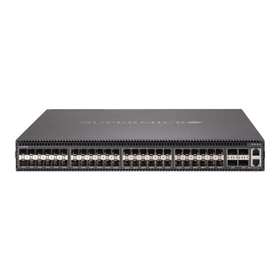
This chapter focuses on making connections to switch network interfaces, including how to install optional transceivers, and details on network cable specifications. The SSE-X3348S/SSE-X3348SR switch features 48 10G SFP+ slots, four 40G QSFP+ transceiver slots, and two 1G RJ-45 ports. The sections that follow describe these interfaces. -
Page 52: Understanding The Port Status Leds
SSE-X3348S/SSE-X3348SR Switch Installation Manual Understanding the Port Status LEDs The switch includes LED indicators for each port to indicate link status and network activity. The port LEDs are shown below and described in the following table. Figure 5-1. Port Status LEDs... -
Page 53: How To Install An Sfp/Sfp+/Qsfp+ Transceiver
Chapter 5: Making Network Connections How to Install an SFP/SFP+/QSFP+ Transceiver The switch provides slots for optional SFP, SFP+, and QSFP+ transceivers. The supported transceiver types are listed below: • 40 Gbps Ethernet QSFP+ transceivers • 40GBASE-CR4 • 40GBASE-SR4 • 10 Gbps Ethernet SFP+ transceivers •... - Page 54 SSE-X3348S/SSE-X3348SR Switch Installation Manual Figure 5-2. Inserting an SFP+ Transceiver into a Slot 10G SFP+ Transceiver...
-
Page 55: How To Connect To Twisted-Pair Copper Ports
Chapter 5: Making Network Connections How to Connect to Twisted-Pair Copper Ports The RJ-45 management port on the switch supports automatic MDI/MDI-X pinout configuration, so you can use standard straight-through twisted-pair cables to connect to any other network device (PCs, servers, switches, routers, or hubs). The connection requires an unshielded twisted-pair (UTP) or shielded twisted-pair (STP) cable with RJ-45 connectors at both ends. -
Page 56: 10/100Base-Tx Pin Assignments
SSE-X3348S/SSE-X3348SR Switch Installation Manual 10/100BASE-TX Pin Assignments All 100BASE-TX RJ-45 ports support automatic MDI/MDI-X operation, so you can use straight-through or crossover cables for all network connections to PCs, switches, or hubs. In straight-through cable, pins 1, 2, 3, and 6, at one end of the cable, are connected straight through to pins 1, 2, 3, and 6 at the other end of the cable. -
Page 57: 1000Base-T Pin Assignments
Chapter 5: Making Network Connections 1000BASE-T Pin Assignments All 1000BASE-T ports support automatic MDI/MDI-X operation, so you can use straight-through cables for all network connections to PCs, servers, or switches. The table below shows the 1000BASE-T MDI and MDI-X port pinouts. These ports require that all four pairs of wires be connected. -
Page 58: Connection Procedure
SSE-X3348S/SSE-X3348SR Switch Installation Manual Connection Procedure Follow the procedure below to connect cables to 1000BASE-T RJ-45 twisted-pair copper ports. Connecting Cables to 1000BASE-T RJ-45 Twisted Pair Copper Ports 1. Attach one end of a twisted-pair cable segment to the device’s RJ-45 connector. -
Page 59: How To Connect To Sfp/Sfp+ Fiber Optic Ports
Chapter 5: Making Network Connections How to Connect to SFP/SFP+ Fiber Optic Ports The switch provides 48 slots for SFP/SFP+ fiber-optic transceivers. Note that all 10G SFP+ fiber optic ports operate at 10 Gbps full duplex. All 1000 Mbps SFP fiber optic ports operate at 1 Gbps full duplex. - Page 60 SSE-X3348S/SSE-X3348SR Switch Installation Manual operational temperature of the product. You must also use an approved Laser Class 1 SFP/ SFP+ transceiver. Connecting Cables to SFP/SFP+ Transceiver Ports 1. Remove and keep the fiber port’s rubber cover. When not connected to a fiber cable, the rubber cover should be replaced to protect the optics.
-
Page 61: How To Connect To Qsfp+ Fiber Optic Ports
Chapter 5: Making Network Connections How to Connect to QSFP+ Fiber Optic Ports The switch includes four slots for 40 Gigabit Ethernet QSFP+ fiber-optic transceivers. Table 5-7. Maximum 40 Gigabit Ethernet Fiber Cable Lengths Maximum Cable Fiber Size Fiber Bandwidth Connector Length 40GBASE-SR4... -
Page 62: Dac Connections
SSE-X3348S/SSE-X3348SR Switch Installation Manual Figure 5-6. Making a Connection to a QSFP+ Port QSFP+ Transceiver Port QSFP+ Fiber Optic Cable 4. As a connection is made, check the Link LED on the switch to be sure that the connection is valid. - Page 63 Chapter 5: Making Network Connections Table 5-8. Maximum 10GBASE-CR 10 Gigabit Ethernet Cable Lengths Cable Type Cable Lengths Connector 1 m (3.28 ft) 2 m (6.56 ft) Pre-terminated Direct Attach Cable (DAC) — 3 m (9.8 ft) SFP+ (twinax copper cable) 5 m (16.4 ft) 10 m (32.8 ft) Table 5-9.
-
Page 64: Making Dac Connections
SSE-X3348S/SSE-X3348SR Switch Installation Manual Making DAC Connections To make DAC connections, follow the procedure below. Making DAC Connections 1. Plug the SFP+/QSFP+ transceiver connector on one end of a twinax copper cable segment into an SFP+/QSFP+ slot on the link device. -
Page 65: Chapter 6 Hardware Specifications
Chapter 6 Hardware Specifications This chapter lists and describes hardware specifications for the SSE-X3348S/ SSE-X3348SR switches. Physical Characteristics Physical characteristic specifications for the switches are shown below: Ports 48 10-Gbps SFP+ transceiver slots, 4 40-Gbps QSFP+ transceiver slots and 2 10/100/... -
Page 66: Switch Features
SSE-X3348S/SSE-X3348SR Switch Installation Manual Temperature Operating: 0 °C to 47 °C (32 °F to 116 °F) Storage: -40 °C to 70 °C (-40 °F to 158 °F) Humidity Operating: 5% to 95% (non-condensing) AC Input SSE-X3348S: AC 100-240V, 50-60Hz, 1A Power Supply 100-240 VAC, 50-60 Hz, auto-sensing;... -
Page 67: Standards
Chapter 6: Hardware Specifications Standards Applicable standards for the switches are shown below: • IEEE 802.3-2005 • Ethernet, Fast Ethernet, Gigabit Ethernet • Full-duplex flow control • Link Aggregation Control Protocol • IEEE 802.1Q • IEEE 802.1P • ISO/IEC 8802-3 Compliances Switch compliances are shown below: Emissions... - Page 68 SSE-X3348S/SSE-X3348SR Switch Installation Manual Notes...
-
Page 69: Chapter 7 Switch Management
Chapter 7 Switch Management The SSE-X3348S/SSE-X3348SR switch includes a management agent that allows you to configure or monitor the switch using its embedded management software. To manage the switch, you can make a direct connection to the console port (out-of-band), or you can manage it through a network connection (in-band) using Telnet, Secure Shell (SSH), a web browser, or SNMP-based network management software. -
Page 70: How To Connect To The Console Port
SSE-X3348S/SSE-X3348SR Switch Installation Manual How to Connect to the Console Port The DB-9 Console port (Figure 7-2) on the switch’s rear panel is used to connect to the switch for out-of-band console configuration. The console device can be a PC or workstation running a VT-100 terminal emulator, or a VT-100 terminal. - Page 71 4. Log in to the command-line interface (CLI) using default settings: • User — admin • Password — null (there is no default password) For a detailed description of connecting to the console and using the switch’s command line interface (CLI), refer to the Supermicro Switch CLI Reference Guide.
-
Page 72: How To Reset The Switch
SSE-X3348S/SSE-X3348SR Switch Installation Manual How to Reset the Switch The Reset button (Figure 7-4) on the switch can be used to restart the device and set the configuration back to factory default values. Use a long thin object, such as the end of a paperclip, to depress the Reset button. One push of the button restarts the system software using default values. -
Page 73: Chapter 8 Troubleshooting
For more information on connecting to the console port and using the CLI, refer to the Supermicro Switch CLI Reference Guide. Note a POST failure normally indicates a serious hardware fault that cannot be rectified or worked around. -
Page 74: Installation
SSE-X3348S/SSE-X3348SR Switch Installation Manual Installation Verify that all system components have been properly installed. If one or more components appear to be malfunctioning (such as the power cord or network cabling), test them in an alternate environment where you are sure that all the other components are functioning properly. - Page 75 Disclaimer The products sold by Supermicro are not intended for and will not be used in life support systems, medical equipment, nuclear facilities or systems, aircraft, aircraft devices, aircraft/emergency communication devices or other critical systems whose failure to perform be reasonably expected to result in significant injury or loss of life or catastrophic property damage.
- Page 76 SSE-X3348S/SSE-X3348SR Switch Installation Manual...
Need help?
Do you have a question about the SSE-X3348S and is the answer not in the manual?
Questions and answers