Table of Contents
Advertisement
User's Manual
➢
To ensure safe usage and full performance of this product, please be sure to read through this
manual completely.
➢
To ensure immediate access whenever needed, store this manual in a safe location.
➢
Unauthorized copying, quotation, or translation of this manual, in whole or in part, without the
written approval of Roland DG Corp., is prohibited.
➢
The contents of this document and the specifications of this product are subject to change without
notice.
➢
Roland DG Corp. assumes no responsibility for any loss or damage relating to this product, regard-
less of any defect in this product or this manual. Such loss or damage, whether direct or indirect,
includes, but is not limited to, that arising from the specifications or performance of this product,
that due to failure of the product to perform, and that arising from any article made using this
product.
Advertisement
Table of Contents

Related Manuals for Roland Metaza MPX-80


Summary of Contents for Roland Metaza MPX-80
- Page 1 ➢ Roland DG Corp. assumes no responsibility for any loss or damage relating to this product, regard- less of any defect in this product or this manual. Such loss or damage, whether direct or indirect, includes, but is not limited to, that arising from the specifications or performance of this product, that due to failure of the product to perform, and that arising from any article made using this product.
-
Page 2: For Canada
For the USA FEDERAL COMMUNICATIONS COMMISSION RADIO FREQUENCY INTERFERENCE STATEMENT This equipment has been tested and found to comply with the limits for a Class A digital device, pursuant to Part 15 of the FCC Rules. These limits are designed to provide reasonable protection against harmful interference when the equipment is operated in a commercial environment. -
Page 3: Table Of Contents
Contents To Ensure Safe Use ........................3 Important Notes on Handling and Use ..................... 8 About the Documentation for This Machine ..................9 Chapter 1 Getting Started ........................ 11 1-1 About the Machine .............................. 12 Features ............................12 Names and Functions ........................13 1-2 Checking the Included Items .......................... - Page 4 ® ® Windows is a registered trademark or trademark of Microsoft Corporation in the United States and/or other countries. Company names and product names are trademarks or registered trademarks of their respective holders. http://www.rolanddg.com/ Copyright © 2007 Roland DG Corporation...
-
Page 5: To Ensure Safe Use
To Ensure Safe Use Improper handling or operation of this machine may result in injury or damage to property. Points which must be observed to prevent such injury or damage are described as follows. About WARNING and CAUTION Notices Used for instructions intended to alert the user to the risk of death or severe WARNING injury should the unit be used improperly. - Page 6 Continuing to use the machine may result in fire, Doing so may result in fire or electrical shock. electrical shock, or injury. Contact your autho- rized Roland DG Corp. dealer. Never allow any foreign object to get in- side. Never expose to liquid spills.
- Page 7 To Ensure Safe Use Important notes about the power cord, plug, and electrical outlet Never place any object on top or subject to Never allow to get wet. damage. Never bend or twist with undue force. Never make hot. Never pull with undue force. Dust may cause fire.
- Page 8 To Ensure Safe Use The head area becomes hot WARNING Never touch the head immediately after printing has finished. Doing so may cause burns.
-
Page 9: Warning Label
To Ensure Safe Use Warning Label Warning label is affixed to make areas of danger immediately clear. The meaning of the label is as follows. Be sure to heed its warnings. Also, never remove the label or allow it to become obscured. Caution: High Temperature Never touch immediately after printing. -
Page 10: Important Notes On Handling And Use
Important Notes on Handling and Use This machine is a precision device. To ensure the full performance of this machine, be sure to observe the following important points. Failure to observe these may not only result in loss of performance, but may also cause malfunction or breakdown. This Machine is a Precision Device. -
Page 11: About The Documentation For This Machine
You view this documentation on your computer screen. Installing the respective programs makes these available for viewing. They describe in detail the commands used in the programs. For more information about how to view these, refer to the Roland Software Package Software Guide. -
Page 13: Chapter 1 Getting Started
Chapter 1 Getting Started... -
Page 14: About The Machine
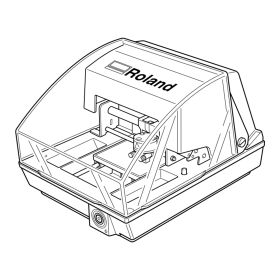
1-1 About the Machine Features This machine is a metal printer. It prints images by striking detailed points using a marking pin mounted in a head. Chapter 1 Getting Started... -
Page 15: Names And Functions
1-1 About the Machine Names and Functions Main Unit Cover Head unit This moves up and down, bringing the tip of the head (the marking pin) in line with the surface of the material. Head Knob This secures the head unit and Brush determines the head height when performing printing with-... - Page 16 1-1 About the Machine Head Marking pins Nine pins are arranged in the head. Printing is performed using any single one of these. Material Retainers Adhesive sheet Material is placed on the adhesive sheet, which then holds the material in place. This lets you immobilize objects without having to use commercially available tape or the like.
-
Page 17: Checking The Included Items
AC adapter Power cord (one installed on the unit by default) Adhesive sheet Center vice Test-use printing material (installed on the unit by default) Roland Software Package User's manual USB cable CD-ROM (this document) Software Guide Chapter 1 Getting Started... -
Page 19: Chapter 2 Getting Ready To Print
Chapter 2 Getting Ready to Print... -
Page 20: Installation
2-1 Installation Installation Environment Install in a quiet, stable location offering good operating conditions. An unsuitable location can cause accident, fire, faulty operation, or breakdown. Install in a location that is level and stable. WARNING Installation in an unsuitable location may cause an accident, including a fall or tipover. ➢... -
Page 21: Unpacking
2-1 Installation Unpacking Retaining materials are attached to protect the machine from vibration during shipment. Remove these after emplace- ment. ➢ Remove all Retaining materials. Any that remain may cause faulty operation or breakdown when the power is switched on. ➢... -
Page 22: Cable Connections
USB cable Computer DO NOT connect a USB cable at this point. Follow the instructions in the separate Roland Software Pack- age Software Guide to make the connection. P. 9, "About the Documentation for This Machine" ➢Never connect two or more machines to one computer. -
Page 23: Installing The Software
2-3 Installing the Software Installing and Setting up the Included Software You install and set up the following programs and other software on the included CD-ROM (Roland Software Package). ➢ Windows driver ( METAZA driver ) ➢ Roland METAZAStudio ➢ Roland SFEdit2 ➢... -
Page 24: Metazastudio Settings
After you finish installing and setting up METAZAStudio, continue by making the setting for the printer. Be sure to make the setting before use. Procedure – Click [Start], then click [All Programs] (or [Programs]). Click [Roland METAZAStudio], then click [METAZAStudio]. — Go to the [File] menu and click [Set up the printer]. The [Print Setup] dialog box appears. -
Page 25: Chapter 3 Performing Printing
Chapter 3 Performing Printing... -
Page 26: Switching The Power On And Off
3-1 Switching the Power On and Off Switching On the Power Press the Power/Movement button. The Power/Movement button lights up, and the head and table move as follows. ➢ Head: This rises to the highest position, then moves to the left edge. ➢... -
Page 27: Starting Metazastudio
3-2 Starting METAZAStudio Starting METAZAStudio Click [Start], then click [All Programs] (or [Pro- grams]). Click [Roland METAZAStudio], then click [METAZAStudio]. After the opening screen, the screen for METAZAStudio appears. For information on how to view this window, see the following page. -
Page 28: Names And Functions Of Metazastudio Screen Items
3-2 Starting METAZAStudio Names and Functions of METAZAStudio Screen Items Menu Bar Runs the various commands for METAZAStudio. METAZAStudio online help ("Com- mands") Toolbar The toolbar is provided with buttons for running METAZAStudio commands such as [Material] and [Open]. METAZAStudio online help ("Com- mands"... -
Page 29: Getting Ready To Print
3-3 Getting Ready to Print The Printable Area The machine's printable area is as follows. Expanded printing area (80 x 80 mm (3.1 x 3.1 in.)) Note : Depending on the mate- rial and the image, the printing results in the expanded area may be uneven. -
Page 30: Preparing Material To Print
3-3 Getting Ready to Print Preparing Material to Print Prepare material that meets all of the following conditions. Loading material that is larger or thinner than this may cause the material to warp during printing and strike the head, damaging the marking pin. Thickness When using the adhesive sheet:... - Page 31 3-3 Getting Ready to Print Cross-section of printing material When using an adhesive sheet When using an adhesive sheet. Without a head cap or a centervice. ➢ Edge of the material must not ➢ The back surface must be flat, ➢...
-
Page 32: Preparing The Image
3-3 Getting Ready to Print Preparing the Image Prepare an image (such as a photograph or drawing) for printing. Data formats supported by METAZAStudio ➢ Files in JPEG format ➢ Files in BMP (bitmap) format ➢ Files in AI or EPS format created by Illustrator version 7 or 8 ➢... -
Page 33: Loading Material (Using The Adhesive Sheet)
3-4 Loading Material (Using the Adhesive Sheet) Loading Material Using the Adhesive Sheet Procedure – Attach a head cap. Fit the head cap into place on the tip of the head. The head cap is attached correctly when its tab clicks into place in the hole in the head. Head Head P. -
Page 34: Handling Of The Adhesive Sheet
3-4 Loading Material (Using the Adhesive Sheet) The procedure from this point on is for when you’re not using the head cap. ™ Press the Power/Movement button. The table and head move, and stop at the lo- cation where the tip of the nose cap touches the surface of the material. -
Page 35: Loading Material (Using The Center Vise)
3-5 Loading Material (Using the Center Vise) Using the Center Vise With the center vise, you secure material in place by clamping it in the vise. The act of securing material in place with the vise always determines the center position of the material in the horizontal direction at the horizontal center position of the machine’s table. -
Page 36: Loading Material Using The Center Vise
3-5 Loading Material (Using the Center Vise) Loading Material Using the Center Vise Procedure – Attach a head cap. Fit the head cap into place on the tip of the head. The head cap is attached correctly when its tab clicks into place in the hole in the head. Head Head P. - Page 37 3-5 Loading Material (Using the Center Vise) ™ Mount the center vise. Fit the tabs on the bottom of the center vise Center vice into the holes in the table on the unit. (Remove the adhesive sheet first.) If you’re performing printing with the head cap attached, this completes loading of the material. If you’re performing printing with no head cap attached, then go on to the following steps.
-
Page 38: Creating Printing Data (Printing On Flat Material)
3-6 Creating Printing Data (Printing on Flat Material) This section describes how to create data, using printing of a plate like the one shown below as an example. P. 28, "Preparing Material to Print" 40mm 25mm Information on how to create data for printing on cylindrical material and * There is a margin in the other curved surfaces is here: P. -
Page 39: Step 2 : Import The Image
3-6 Creating Printing Data (Printing on Flat Material) ˜ Make the setting for the margins. Click [File], then click [Preferences]. The [Preferences] dialog box appears. Set “Margin” to “1 mm.” (This is set at 1 millimeter by default.) Click [OK]. Important ! For printing on a flat plate, make the margin at least one millimeter. - Page 40 3-6 Creating Printing Data (Printing on Flat Material) — At [Look in], select the location of the file. At [Files of type], select either [Pic- ture file] or [Adobe Illustrator file]. Select the file you want. Click [Open]. The specified image is imported and dis- played with the margins you set.
-
Page 41: Step 3 : Save The File
3-6 Creating Printing Data (Printing on Flat Material) Step 3 : Save the File Save the printing data in a file. Procedure – Click The [Save As] dialog box appears. — For [Save in], specify where to save the file. Type in a file name. -
Page 42: Starting Printing
– Close the cover. — Click The [Print Setup] dialog box appears. ˜ Make sure [Roland MPX-80] is cho- sen as the printer name. Click [Properties]. ™ Click the [Image Correction] tab. Select [Material]. Select either the composition or the prod- uct code of the material. - Page 43 3-8 Starting Printing š Click [OK]. The printing data is sent to the machine and printing starts. › After printing has finished, open the cover and detach the material. If the Material Is Difficult to Detach When Using the Adhesive Sheet If the material is difficult to detach, inserting a thin, flat object (such as a piece of stiff paper or cardboard) between the adhesive sheet and the material may make it easier to dislodge.
-
Page 44: Stopping Printing Operations
Click [Printers and Other Hardware], then click [Printers and Faxes]. Windows 2000 Click [Start]. Click [Settings], then click [Printers]. ˜ Double-click the [Roland MPX-80] icon. ™ At the [Printers] menu, click [Cancel All Documents] (or [Purge Print Documents]). š If the message shown in the figure appears, click “Yes.”... -
Page 45: Chapter 4 More Advanced Operations
Chapter 4 More Advanced Operations... -
Page 46: Tips And Tricks For Image Layout
4-1 Tips and Tricks for Image Layout Keeping Only the Required Portion of an Image (Trimming) You can cut an original image to remove unneeded areas and keep just the required portion. This operation is called “trimming.” In this example, you use the printing data created at page 36, “Creating Printing Data (Printing on Flat Material).” P. -
Page 47: Adjusting The Location, Size, Or Angle Of An Image
4-1 Tips and Tricks for Image Layout Adjusting the Location, Size, or Angle of an Image You can adjust the location, size, and angle of a placed image to achieve the layout you want. In this example, you use the printing data created at page 44, “Keeping Only the Required Portion of an Image (Trimming).”... - Page 48 4-1 Tips and Tricks for Image Layout ˜ Adjust the angle. With the handles present at the four corners of the image, click the image a second time. The shape of the handles at the four cor- ners changes to (G). Line up the pointer with a handle.
-
Page 49: Enclosing An Image In A Frame
4-1 Tips and Tricks for Image Layout Enclosing an Image in a Frame You can change the arrangement of printing data by placing a frame around an image. You use frames registered in what’s called METAZAStudio’s “library.” The library contains a number of preregistered frames, and you can also register new ones. - Page 50 4-1 Tips and Tricks for Image Layout ˜ Drag the Handles ( I ) around the frame to adjust its size and location. Adjust the location and size so as to enclose the image. The adjustment methods are the same as the methods for adjusting the loca- tion and size of an image.
-
Page 51: Tips And Tricks For Text Layout
4-2 Tips and Tricks for Text Layout Enter the Text Here you type in the text to print. Procedure – Click — Click somewhere on the material, then type in the text. Chapter 4 More Advanced Operations... -
Page 52: Landscape Or Fan Layout
4-2 Tips and Tricks for Text Layout Landscape or Fan Layout After arranging the text in landscape layout, you can change the arrangement to a fan layout. Procedure – Enter text. P. 49, "Enter the Text" Arrange the text horizontally. Click The [Properties] dialog box appears. -
Page 53: Adjusting Laid-Out Text
4-2 Tips and Tricks for Text Layout Adjusting Laid-out Text For laid-out text, in the same way as for images, you can shift the location where it’s placed and change its size and angle. You can also change the type of fill used. P. - Page 54 4-2 Tips and Tricks for Text Layout Drag to change the angle of the text. You can change the angle by up to 360 degrees. Holding down the keyboard’s SHIFT key as you drag makes the angle change by 45 de- grees at a time.
-
Page 55: Laying Out Text Along A Shape
4-2 Tips and Tricks for Text Layout Laying Out Text along a Shape Here you lay out text along a shape you have made using the drawing tools. Procedure – Click a drawing tool. In this example you use In the editing window, create a shape on the material. -
Page 56: Enter Text
4-2 Tips and Tricks for Text Layout ˜ Enter text. P. 49, "Enter the Text" The text is laid out along the shape. Important ! Layout on an integrated polyline is not possible. METAZAStudio online help ("Commands" > "[Object] menu" > "Convert to Polyline", "Integrate Plylines") You can adjust the size and position of the laid-out text, or change its format. -
Page 57: Changing The Format Of Text
4-2 Tips and Tricks for Text Layout Changing the Format of Text In the [Properties] window, at the [Format] tab, you can change such properties as the font of laid-out text, as well the height and width of the characters. For detailed information about the settings, refer to the online help for METAZAStudio. -
Page 58: Adjusting Brightness And Contrast
4-3 Adjusting Brightness and Contrast Checking the Finished Results in the Preview Window At the preview window, you can adjust the brightness, contrast, and gamma correction. An image with clearly defined light and dark areas produces attractive printed results. Adjust to match the image. Click Preview window appears. -
Page 59: Adjusting An Image In The Preview Window
4-3 Adjusting Brightness and Contrast Adjusting an Image in the Preview Window Brightness This adjusts the overall brightness. Mak- ing the value too large can destroy the balance, so it may be a good idea to ad- just it to the absolute minimum necessary. Contrast This mainly adjusts highlights (the bright- est areas) and shadows (the darkest areas). -
Page 60: Creating Data For Printing On A Curved Surface
4-4 Creating Data for Printing on a Curved Surface With this machine, using a head cap lets you perform printing on cylinders and other examples of material whose surface height is not uniform. This section describes how to create data, using printing on a cylindrical material like the one shown below as an example. - Page 61 4-4 Creating Data for Printing on a Curved Surface — Click [File], then click [Set up the printer]. The [Print Setup] dialog box appears. ˜ Make sure [Roland MPX-80] is choosen as the printer name. Click [Properties]. ™ Make the [Diameter] and [Material Ori- entation] settings for the cylindrical material.
-
Page 62: Step2 : Enter Text And Adjust The Layout
4-4 Creating Data for Printing on a Curved Surface Step2 : Enter Text and Adjust the Layout Type in the text to print, then adjust how it’s laid out. Procedure – Enter a single character of text in the printing area. P. - Page 63 4-4 Creating Data for Printing on a Curved Surface ˜ Enter text remained, and adjust the po- sition. The on-screen table scale corresponds to the scale for the center vise as shown in the figure. Carefully adjust the positioning to enable the text to be printed at the location you want. P.
-
Page 64: Printing Materials Of A Wide Variety Of Shapes
4-5 Printing Materials of a Wide Variety of Shapes How to Register New Material METAZAStudio includes preregistered material of four shapes, and you can also register new material. Printing material without first registering it is possible, but in such cases the printing area is restricted, and the marking pins may be damaged by striking the edge of the material. -
Page 65: Other Handy Features
4-6 Other Handy Features A Wide Variety of Operations You Can Accomplish with METAZAStudio METAZAStudio offers a wide variety of features for editing imported images and creating printing data. For more information on how to operate METAZAStudio, refer to the online help for the program. P. -
Page 66: Driver Settings
Windows 2000 Click [Start]. Click [Settings], then click [Printers]. — Right-click [Roland MPX-80]. Click [Printing Preferences]. The setting window appears. About the Setting Window Going to the METAZAStudio [File] menu and clicking [Print Setup], then, in the [Print Setup] window, clicking [Properties], displays the same window as the one that appears using "Displaying the Setting Window,"... -
Page 67: Viewing The Online Help For The Driver
4-7 Driver Settings Viewing the Online Help for the Driver For detailed information about the values you can set using the driver, see the online help for the driver. To view the online help for the driver, go to the driver’s setting window, and click the [Help] button. P. -
Page 68: Sfedit2
What's SFEdit2 ? SFEdit2 is a program on the CD-ROM included with the machine (the Roland Software Package) that lets you create and edit stroke fonts. Stroke fonts are line drawings created by automatically extracting the centerlines from a TrueType font. -
Page 69: Chapter 5 Maintenance And Adjustment
Chapter 5 Maintenance and Adjustment... -
Page 70: Daily Care
5-1 Daily Care Daily Care WARNING Never use gasoline, alcohol, thinner, or any other flammable material. Doing so may cause fire. Never touch the heads immediately after printing has finished. CAUTION Doing so may cause burns. ➢This machine is a precision device, and is sensitive to dust and dirt. Be sure to carry out day-to-day cleaning. ➢Never use solvents such as thinner, benzine, or alcohol. -
Page 71: The Replacement Cycle For The Head Cap
5-1 Daily Care The Replacement Cycle for the Head Cap The head cap is due for replacement when the triangle at its tip (see the figure below) is worn away. Replace it with a new head cap. P. 31, "Loading Material (Using the Adhesive Sheet)", p. 33, "Loading Material (Using the Center Vise)" Replace when this triangle disappears. -
Page 72: Maintenance Of The Head And The Marking Pins
5-2 Maintenance of the Head and the Marking Pins You perform all head cleaning and maintenance of the marking pins using the included MPX-80 Head Manager program. The machine's head has nine pins. Printing is performed using these pins one at a time. If the tip of the pin in use becomes worn, you can change the pin used for printing. -
Page 73: Head Cleaning
5-2 Maintenance of the Head and the Marking Pins Head Cleaning Clean away any fine grime around the head. Perform cleaning periodically. Procedure – Detach the center vise or the adhesive sheet and loosen the knob. Detach the center vise or adhesive sheet. -
Page 74: Checking The State Of The Marking Pins
5-2 Maintenance of the Head and the Marking Pins Checking the State of the Marking Pins The state of each pin is shown. If the indicator for the pin you're using is red, then replace it with a new pin. If attractive printing is impossible or printed images are uneven even though the scale is not red, then change to a new pin. -
Page 75: Changing The Pin Used For Marking
5-2 Maintenance of the Head and the Marking Pins Changing the Pin Used for Marking Follow the steps below to change the marking pin. Procedure – Start MPX-80 Head Manager. P. 70, "Starting MPX-80 Head Manager" — Choose the number of the pin to use next. Click [Apply Pin Change]. -
Page 76: Adjusting The Striking Force Of The Pins
5-2 Maintenance of the Head and the Marking Pins Adjusting the Striking Force of the Pins You can individually adjust the striking force of each separate pin. Pin adjustment involves striking the pattern shown in the figure. Prepare a piece of test-use printing material (brass) or other material measuring about 60 mm (2.3 in.) by 60 mm (2.3 in.). -
Page 77: Head Replacement
Prepare a piece of test-use printing material (brass) included with the replacement head (MPH-70), or another piece of material measuring about 60 mm (2.3 in.) by 60 mm (2.3 in.). The replacement head is sold separately. Consult your authorized Roland DG Corp. dealer. Adjustment pattern Procedure ➢Never quit the replacement operation while partway through. -
Page 78: Adjustment Of The Origin-Point Location
5-4 Adjustment of the Origin-point Location Adjusting the Location of the Machine's Origin Point The machine's printing origin point is at the center of the table's scale. When you want to adjust the origin-point location, output calibration data to verify the location of the origin point. Print calibration data. - Page 79 Click [Printers and Other Hardware], then click [Printers and Faxes]. Windows 2000 Click [Start]. Click [Settings], then click [Printers]. The [Printers] folder opens. ˜ Right-click [Roland MPX-80]. Click [Printing Preferences]. The setting window appears. ™ Click the [Material] tab. In the width and length fields for [Offset], enter the displacement values you noted in step 1.
-
Page 80: Composition Registration And Striking-Force Adjustment
Click [Printers and Other Hardware], then click [Printers and Faxes]. Windows 2000 Click [Start]. Click [Settings], then click [Printers]. — Right-click [Roland MPX-80]. Click [Properties]. ˜ Click the [Image Correction] tab. For [Material], select a custom material (set- tings a through d). - Page 81 5-5 Registration of Custom Material ™ Enter a name for the composition you’re registering. Adjust the impact values. The printing results vary according to the hardness of the material. Adjust to match the material. Raise • When dark areas of the image are not struck Lower •...
-
Page 83: Chapter 6 Appendix
Chapter 6 Appendix... -
Page 84: What To Do If
6-1 What to Do If The machine doesn't run even when printing data is sent. The image is unattractive. Is the power switched on? Are the settings for the material in the driver's set- Make sure the Power/Movement button light is on. If it is ting window correct? dark, press the Power/Movement button to switch on the Choose the composition of the loaded material. -
Page 85: The Image Is Uneven
P. 31, "Loading Material Using the Adhesive Sheet" material that has a level printing surface. 2. Go into the [Printers] folder. Right-click the [Roland MPX- P. 27, "Head Caps", p. 28, "Preparing Material to Print" 80] and open the setting screen for the METAZA driver. -
Page 86: When Moving The Machine
6-2 When Moving the Machine When moving the machine, be sure to attach the retaining materials. Moving the machine without attaching the retaining materials may result in damage to the machine. Procedure – Switch on the power. P. 24, "Switching On the Power" —... - Page 87 6-2 When Moving the Machine š Attach the retaining materials in the order shown in the figure. Retainer B Lift the head unit slightly. Retainer A Retaining screw Use the retaining screw stored here. › Lift the knob and secure in place. Lift the knob until it touches the head unit, then lift it up slightly more from that point, and secure it in place at a position where...
-
Page 88: Head Life
As a general guide to its useful life, about 3,600 plates can be printed under the following conditions. Conditions of Use Material used : MD-NI (Roland nickel-plated plate) Printing area : 30 mm (1.1 in.) X 23 mm (0.9 in.) -
Page 89: Locations Of The Power Rating And Serial Number Labels
6-4 Locations of the Power Rating and Serial Number Labels Serial Number This is require when you seek maintenance, servicing, or support. Never peel off the la- bel or let it get dirty. Power Rating Use an electrical outlet that meets the re- quirements for voltage, frequency, and am- perage given here. -
Page 90: Main Unit Specifications
6-5 Main Unit Specifications Main Specifications MPX-80 Printable material Gold, silver, copper, platinum, brass, aluminium, iron, stainless steel, etc. (Vickers hardness [HV] of the printing surface must be 200 or less.) Loadable material size Maximum 100 mm (width) x 100 mm (height) x 40 mm (thickness) (3.9 in. - Page 100 R1-070820...
Need help?
Do you have a question about the Metaza MPX-80 and is the answer not in the manual?
Questions and answers