Table of Contents
Advertisement
The information presented in this publication has been
carefully checked for reliability; however, no responsibility
is assumed for inaccuracies. Specifications are subject to
change without notice.
Trademarks
PS/2, OS/2, IBM, PC/AT, and PC/XT are trademarks of
International Business Machines Corporation.
®
Intel and Pentium
are trademarks of Intel Corporation.
AMI is a trademark of American Megatrends Inc.
MS-DOS and WINDOWS 95/98/NT are registered
trademarks of Microsoft Corporation.
PC-cillin and ChipAwayVirus are trademarks of Trend
Micro, Inc.
AMD is a trademark of Advanced Micro Devices Inc.
Cyrix is a trademark of Cyrix Corporation.
IDT is a trademark of Integrated Devices Technology
Corporation.
SiS is a trademark of Silicon Integrated Systems
Corporation.
Copyright (C) 1999.
All Rights Reserved.
MS6380SG, Version 3.2
S5X/January 1999
Advertisement
Table of Contents

Related Manuals for MATSONIC MS6380SG


Summary of Contents for MATSONIC MS6380SG
- Page 1 AMD is a trademark of Advanced Micro Devices Inc. Cyrix is a trademark of Cyrix Corporation. IDT is a trademark of Integrated Devices Technology Corporation. SiS is a trademark of Silicon Integrated Systems Corporation. Copyright (C) 1999. All Rights Reserved. MS6380SG, Version 3.2 S5X/January 1999...
-
Page 2: Table Of Contents
Contents Chapter 1: Introduction ................1 Key Features ..................2 Unpacking the Mainboard & Static Electricity Precautions ....5 Chapter2: Hardware Configuration ............6 Mainboard Component Locations ............7 CPU Installation ................... 8 CPU Speed Setting ................. 8 Memory Installation ................8 Jumper Settings .................. - Page 3 J5 - Digital Audio Connectors ............19 CD2 - SPDIF OUT Signal Level Selector ........19 CD1 - Internal SPDIF IN Connector ..........19 Notice for Sound Pro drivers install and application ..... 20 The 4 Speakers System ..............21 JP3 - Onboard Sound Pro Selector ..........
-
Page 5: Chapter 1 Introduction
Chapter 1 Introduction This mainboard is a SiS530 100MHz highly integrated high-performance mainboard based on the advanced Socket 7 microprocessor and provides CPU Plug and Play feature for faster and easier CPU installation. The mainboard features highly flexible configurations and is fully IBM PC/AT compatible. -
Page 6: Key Features
Chapter 1 Key Features The advanced features of the mainboard including: Supports P54C/P55C (MMX) Pentium® CPUs and Cyrix/IBM 6x86L/6x86MX/MII, AMD K6/K6-2, IDT C6 CPUs with Frequency at 60/66/75/83/95/100MHz; Provides CPU Plug and Play features for faster and easier CPU installation; Memory: —... - Page 7 Introduction — maximum 8MB frame buffer share from the system memory — high resolution graphic modes up to 1600x1200 Onboard CMI 8338 PCI Sound Features: — HRTF 3D positional audio supports Direct Sound 3D, A3D interfaces, and four speakers mode. —...
- Page 8 Chapter 1 Bundled: — AMI Desktop Client Manager detects abnormal condition through the network link or self core — PC-cillin98 (OEM) provides automatic virus protection for Windows 95/98 and the Internet Dimension: — Micro ATX Form Factor, 24.5cm (L) x 19cm (W)
-
Page 9: Unpacking The Mainboard & Static Electricity Precautions
Introduction Unpacking the Mainboard & Static Electricity Precautions This Mainboard package contains the following items: 1. This Mainboard and the Device Driver 2. This User’s Guide and AT cables 3. SPDIF/IN cable(optional) 4. Optional Digital Audio ribbon cable/bracket 5. COM2 ribbon cable/bracket The mainboard is easily damaged by static electricity. -
Page 10: Chapter2: Hardware Configuration
Chapter 2 Hardware Configuration Before you install the mainboard into the system chassis, you may find it convenient to first configure the mainboard’s hardware. This chapter describes how to set jumpers and install memory modules, and where to attach components, however, the CMOS jumper is set on the “Clear”... -
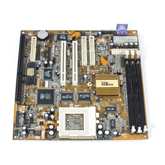
Page 11: Mainboard Component Locations
Hardware Configuration Mainboard Component Locations Line in/ USB ( B ) Line out COM1 VGA1 PS/2-KBD Rear USB ( T ) PS/2-Mouse PRN1 Game PWR1 PCI3 PCI2 PCI1 COM2 DIMM1 DIMM2 DIMM3 Socket FDC 1 Chipset Battery Chipset FAN1 IDE2 IDE1 Figure 2-1. -
Page 12: Cpu Installation
Chapter 2 CPU Installation CPU Speed Setting This mainboard provides CPU Plug and Play technology, so that there is no need to do the CPU jumper setting. Enter the BIOS Setup and select “CPU Plug and Play Setup”. Choose the correct CPU speed to match your CPU installed. -
Page 13: Jumper Settings
Hardware Configuration Jumper Settings JP6 - CMOS RAM Clear Selector The battery on this mainboard is designed to retain the system configuration in CMOS RAM. In order to save the life of the battery, this jumper is set to "Clear CMOS" position when this board is shipped, therefore you need to set this jumper to "Normal"... -
Page 14: Atx Functions & Connectors
Chapter 2 ATX Functions & Connectors This mainboard supports ATX power and ACPI specification. The ATX functions and connectors are described below. Software Power-Off Follow the steps below to use the “Software Power-Off Control” function in Windows 95/98 with ATX power supply. -
Page 15: Jp4 - Lan Wake On Connector
Hardware Configuration JP4 - LAN Wake On Connector Connect this connector to the LAN card which supports ACPI specification. 5V Standby Ground Active High Chipset Chipset Alarm Wake Up If you want to autoboot the system at a certain time, set the function of RTC Alarm time properly and the function of RTC Alarm Power On in the BIOS Setup section will be set to "Enabled". -
Page 16: Jp1 - Keyboard Power On Selector
Chapter 2 JP1 – Keyboard Power On Selector This jumper is designed for the user to turn on the system by using the keyboard, and, the user must enter BIOS Setup to set the “Keyboard Power On” option in the Advanced Chipset Setup. -
Page 17: J9(21,22) - Power Button/Suspend Switch Connector
Hardware Configuration J9 (21,22) – Power Button/SuspendSwitch Connector Attach the ATX power button/suspend switch cable to this connector. In the AT power system, this connector will act as a suspend switch; and in the ATX power system, this connector will be not only an ATX power button but a suspend switch as well. -
Page 18: Connectors
Chapter 2 Connectors Attach system components and case devices to the mainboard via the mainboard connectors. A description of each connector follows. See Figure 2–1 for the location of the connectors on the mainboard. Note: Make sure that the power is turned off before making any connection to the board. -
Page 19: J6 - Infrared Connector
Hardware Configuration J6 – Infrared Connector The mainboard provides a 5-pin Infrared connector for infrared devices. You must configure the setting for infrare d device through the Peripheral Setup in BIOS Setup section. Chipset Chipset FAN1 FAN1 – CPU Fan Power Connector Connect CPU fan cable to this connector. -
Page 20: Case Connectors: J9
Chapter 2 Case Connectors: J9 The case connectors contain: Speaker, Power LED, Keylock, Turbo LED, HDD LED, Reset Switch, and Power Button. Refer to the following drawing for the location on the mainboard. pin1, 3, 5, 7 – Speaker pin2, 4, 6 – Power LED pin8, 10 –... - Page 21 Hardware Configuration J9 (2, 4, 6, 8, 10) – Keylock & Power LED Connector Description LED Output N.C. Ground Keylock Ground J9 (1, 3, 5, 7) – Speaker Connector Description N.C. Ground Data Out J9 (13, 14) – Turbo LED Connector Description 13 (+) Anode...
-
Page 22: Onboard Pci Sound
Chapter 2 Onboard PCI Sound There is a onboard PCI Sound for the 3D multimedia systems. J7/J8 – Analog Audio from CD-ROM Connectors Connect from “AUDIO” output of the CD-ROM driver to these connectors. For Panasonic or compatible type ofCD- ROM, connect to J7 (pin signals assignment is G-L-G-R), and for Sony or compatible type of CD-ROM,connect to J8 (pin signals assignment is L-G-G-R). -
Page 23: J5 - Digital Audio Connectors
Hardware Configuration J5 – Digital Audio Connector Connect this connector to the Aux. Sound ribbon cable/ bracket that contains 3 jacks for Aux IN, SPDIF IN and SPDIF OUT device. Aux IN is called the second Line-in. Connect SPDIF IN to the Mini-Disk to record, and avoid this jack to work simultaneously with the internal SPDIF IN connector. -
Page 24: Notice For Sound Pro Drivers Install And Application
Chapter 2 Notice for PCI Sound application 1. Before you install the PCI Sound drivers, make sure your Operating System has been installed, otherwise the PCI Sound Pro might be detect as "Other Device" by the device manager of your OS. 2. -
Page 25: The 4 Speakers System
Hardware Configuration The 4 Speakers System Onboard Sound provides 2 wave channels (front/rear), known as the 4 speakers system. When application programs via DirectSound® 3D or A3D® interface locate the sound sources to the listener's back, the two rear speakers will work to enhance the rear audio positional effect, so as to complement the insufficiency of using only two front speakers to emulate the audio effect. -
Page 26: Jp3 - Onboard Sound Pro Selector
Chapter 2 (Sound Port) Line-in/Rear Line-out Rear Speakers Speaker Speaker Monitor Speaker Speaker Front Speakers A picture on the 4 speakers application JP3 - Onboard Sound Selector Set this jumper to disable the onboard PCI Sound. Description Disabled Enabled Chipset (default) Chipset... -
Page 27: Chapter3: Bios Setup
Chapter 3 BIOS Setup This chapter explains how to configure the mainboard’s BIOS setup program. The setup program provided with the mainboard is the BIOS from AMI. After you have configured the mainboard and have assembled the components, turn on the computer and run the software setup to ensure that the system information is correct. -
Page 28: Entering Bios Setup
Chapter 3 Entering BIOS Setup To enter the BIOS Setup program: 1. Turn on or reboot the system. A screen appears with a series of diagnostic checks. 2. When “Hit <DEL> if you want to run SETUP” appears, press the <DEL> key to enter the BIOS setup program. -
Page 29: Setup Item
BIOS Setup Setup Items Standard CMOS Setup Choosing the item from the BIOS Setup main menu. All Standard Setup options are described in this section. AMIBIOS SETUP - STANDARD CMOS SETUP (C)1998 American Megatrends, Inc. All Rights Reserved Date (mm:dd:yy) : Tue Nov 24,1998 Time (hh:mm:ss) : 18:44:46 32Bit... -
Page 30: Advanced Cmos Setup
Chapter 3 Floppy Drive Choose the Floppy Drive A or B icon to specify A; B the floppy drive type. The settings are 360KB ", 1.2MB 5 ", 720KB 3 ", 1.44MB 3 ", or 2.88MB 3 ". Advanced CMOS Setup Choosing the item from the BIOS Setup main menu. - Page 31 BIOS Setup Boot Up Num-Lock Set this option to turn on Num Lock key when the system is powered on. Floppy Drive Swap This option allows you to swap floppy drives between A: and B:. Floppy Drive Seek Choose Enabled or Disabled. Disabled provides a faster boot and reduces the possibility of damaging the heads.
-
Page 32: Advanced Chipset Setup
Chapter 3 Video, 32K Shadow; Disabled: The specified ROM is not C800, 16K Shadow; copied to RAM. CC00, 16K Shadow; Enabled: The contents of the ROM area D000, 16K Shadow; are not only copied from ROM D400, 16K Shadow; to RAM for faster execution, D800, 16K Shadow;... - Page 33 BIOS Setup RAS Precharge Set this option to select the proper SDRAM Time RAS precharge time. RAS to CAS Delay Set this option to select the proper delay time of SDRAM RAS to CAS. Share Memory Size Set this option to select the onboard VGA frame buffer size that share from system memory.
- Page 34 Chapter 3 Keyboard Power On Set this option to enable the Keyboard Power On function, and needs ATX power supply, refer to "Keyboard Power-On" in the ATX Functions & Connectors section.
-
Page 35: Power Management Setup
BIOS Setup Power Management Setup Choosing the item from BIOS Setup main menu. AMIBIOS SETUP - POWER MANAGEMENT SETUP (C)1998 American Megatrends, Inc. All Rights Reserved Power Management/APM Disabled RTC Alarm Power On Disabled Green Monitor Power State Suspend RTC Alarm Date RTC Alarm Hour Video Power Down Mode Stand By... - Page 36 Chapter 3 Standby Time out This option specified the length of system (Minute) inactivity while in Full power on state. When this length of time expires, the computer enters Standby power state. Suspend Time Out This option specified the length of a (Minute) period of system inactivity while in Standby state.
-
Page 37: Pci/Plug And Play Setup
BIOS Setup PCI/Plug and Play Setup Choose the item from the BIOS Setup main menu. AMIBIOS SETUP - PCI / PLUG AND PLAY SETUP (C)1998 American Megatrends, Inc. All Rights Reserved Plug and Play Aware O/S Reserved Memory Address C8000 Onboard AGP VGA PCI VGA Palette Snoop Disabled... - Page 38 Chapter 3 DMA Channel 0, These options specify the bus that the specified 1, 3, 5, 6, 7 DMA channel is used on. IRQ3, 4, 5, 7, 9, These options specify the bus that the specified 10, 11, 14, 15 IRQ line is used on.
-
Page 39: Peripheral Setup
BIOS Setup Peripheral Setup Choose the item from the BIOS Setup main menu. AMIBIOS SETUP - PERIPHERAL SETUP (C)1998 American Megatrends, Inc. All Rights Reserved OnBoard FDC Enabled OnBoard Serial Port1 3F8h/COM1 OnBoard Serial Port2 2F8h/COM2 Serial Port2 Mode Normal Ir Duplex Mode Full OnBoard Parallel Port... - Page 40 Chapter 3 Parallel Port Depends on the type of your external device Mode which connects to this port to choose Normal, EPP, or ECP mode. Parallel Port IRQ This option specifies IRQ to parallel port. Parallel Port This option is only available if the setting of the Parallel Port Mode option is EPP/ECP.
-
Page 41: H/W Monitor & Cpu Pnp Setup
BIOS Setup H/W Monitor & CPU PnP Setup Choose this item from the BIOS Setup main menu. AMIBIOS SETUP - H/W Monitor & CPU PnP SETUP (C)1998 American Megatrends, Inc. All Rights Reserved CPU Plug and Play Auto CPU Brand AMD-K6-2 VCCore Voltage 2.2V... -
Page 42: Change Supervisor Password
Chapter 3 –= System Hardware Moniotr =– Temperature; These options are displayed only to show the Current Fan Speed; status of the system hardware. +12.000V; +5.000V; +3.300V; Vcore Change Supervisor Password This item lets you configure the system password which is required every time when the system boots up or an attempt is made to enter the Setup program. -
Page 43: Chapter4: Software Driver
* VGA Driver Path (CD-ROM): \MS6380SG\VGA\ * USB Driver for Windows 95 (CD-ROM): \USB\Eusbsupp\Usbsupp.exe * Sound Driver Path (CD-ROM): \Audio\PCI8338\ * BIOS Update Utility (CD-ROM): \UTILITY\Ami_Flash\Flash807.exe * Bundled PC-cillin Path (CD-ROM): \PC-cillin\ * Bundled ADCM Path (CD-ROM): \MS6380SG\AMI ADCM\...
Need help?
Do you have a question about the MS6380SG and is the answer not in the manual?
Questions and answers