Table of Contents
Advertisement
This publication, including photographs, illustrations and software,
is under the protection of international copyright laws, with all
rights reserved. Neither this manual, nor any of the material
contained herein, may be reproduced without the express written
consent of the manufacturer.
The information in this document is subject to change without
notice. The manufacturer makes no representations or warranties
with respect to the contents hereof and specifically disclaims any
implied warranties of mercha ntability or fitness for any particular
purpose. Further, the manufacturer reserves the right to revise this
publication and to make changes from time to time in the content
hereof without obligation of the manufacturer to notify any person
of such revision or changes.
Trademarks
IBM, VGA, and PS/2 are registered trademarks of International
Business Machines.
Intel, Pentium, Pentium-II, Pentium-III, Pentium 4, MMX,
Celeron and Tualatin are registered trademarks of Intel
Corporation.
Microsoft, MS-DOS and Windows 98/ME/NT/2000/XP are
registered trademarks of Microsoft Corporation.
PC-cillin is a trademark of Trend Micro Inc.
AMI is a trademark of American Megatrends Inc.
MediaRing Talk is a registered trademark of MediaRing Inc.
3Deep is a registered trade mark of E -Color Inc.
It has been acknowledged that all mentioned brands or product
names are trademarks or registered trademarks of their respective
holders.
Mainboard User's Manual
Copyright © 2002
All Rights Reserved
MS9138D Series, V1.3A
VT8751/November 2002
Advertisement
Table of Contents

Related Manuals for MATSONIC MS9138D Series


Summary of Contents for MATSONIC MS9138D Series
- Page 1 3Deep is a registered trade mark of E -Color Inc. It has been acknowledged that all mentioned brands or product names are trademarks or registered trademarks of their respective holders. Copyright © 2002 All Rights Reserved MS9138D Series, V1.3A VT8751/November 2002...
- Page 2 Mainboard User’s Manual Notice: Owing to Microsoft’s certifying schedule is various to every supplier, we might have some drivers not certified yet by Microsoft. Therefore, it might happen under Windows XP that a dialogue box (shown as below) pop out warning you this software has not passed Windows Logo testing to verify its compatibility with Windows XP.
-
Page 3: Table Of Contents
Mainboard User’s Manual Table of Contents Chapter 1: Introduction .............. 1 Key Features..............2 Package Contents ...............5 Static Electricity Precautions ..........6 Pre-Installation Inspection...........6 Chapter 2: Mainboard Installation ..........9 Mainboard Components............10 I/O Ports................11 Installing the Processor.............12 Installing Memory Modules ..........13 Jumper Settings .............. -
Page 5: Chapter 1: Introduction
1: Introduction Chapter 1 Introduction This mainboard has a Socket 478 for the Intel Pentium 4 type of processors supporting front side bus (FSB) speeds up to 400 MHz. This mainboard has the VIA VT8751(P4M266) Northbridge and VT8233 Southbridge chipsets that support AC 97 audio codec, and provide Ultra DMA 33/66/100 function. -
Page 6: Key Features
Mainboard User’s Manual Key Features This mainboard has these key features: Socket 478 Processor ♦ The PGA Socket 478 ♦ Accommodates Intel Pentium 4 CPUs ♦ Supports a front-side bus (FSB) of 400 MHz Chipset There are VT8751 Northbridge and VT8233 Southbridge in this chipset in accordance with an innovative and scalable architecture with proven reliability and performance. - Page 7 1: Introduction Built-in Graphics System ♦ P4M266 integrates S3®’s Savag8™ graphics accelerator into a single chip. P4M266 brings mainstream graphics performance to the Value PC with leading-edge 2D, 3D and DVD video acceleration into a cost effective package. Based on its capabilities, P4M266 is an ideal solution for the consumer, corporate mobile users and entry level professionals.
- Page 8 Mainboard User’s Manual Expansion Options The mainboard comes with the following expansion options: ♦ Two 32-bit PCI slots capable of Ultra DMA bus mastering with transfer rates of 33/66/100 MB/sec ♦ An 4xAGP slot ♦ A CNR (Communications and Networking Riser) slot Onboard I/O Ports The mainboard has a full set of I/O ports and connectors: ♦...
- Page 9 1: Introduction Bundled Software ♦ PC-Cillin 2000 provides automatic virus protection under Windows 98/ME/NT/2000/XP ♦ MediaRing Talk provides PC to PC or PC to Phone internet phone communication ♦ 3Deep delivers the precise imagery and displays accurate color in your monitor ♦...
-
Page 10: Package Contents
Mainboard User’s Manual Package Contents Attention: This mainboard serial has two models, MS9138D+(LAN) and MS9138D(without LAN). Please contact your local supplier for more information about your purchased model. Each model will support different specification listed as below: Model Specification MS9138D+ Onboard LAN PHY chip (U15), USB + RJ-45 LAN connector MS9138D... -
Page 11: Static Electricity Precautions
1: Introduction Static Electricity Precautions Static electricity could damage components on this mainboard. Take the following precautions while unpacking this mainboard and installing it in a system. 1. Don’t take this mainboard and components out of their original static-proof package until you are ready to install them. 2. - Page 12 Mainboard User’s Manual...
-
Page 13: Chapter 2: Mainboard Installation
2: Mainboard Installation Chapter 2 Mainboard Installation To install this mainboard in a system, please follow these instructions in this chapter: Identify the mainboard components Install a CPU Install one or more system memory modules Make sure all jumpers and switches are set correctly Install this mainboard in a system chassis (case) Connect any extension brackets or cables to connecting headers on the mainboard... -
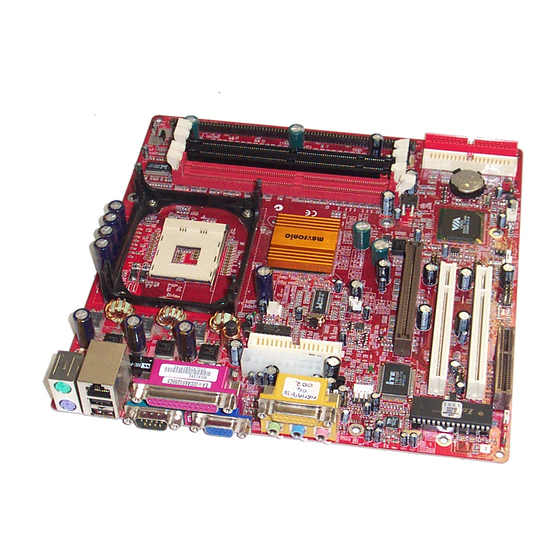
Page 14: Mainboard Components
Mainboard User’s Manual Mainboard Components Identify major components on the mainboard via this diagram underneath. Note: Those jumpers of mainboard not appearing in this illustration are for testing only. -
Page 15: I/O Ports
2: Mainboard Installation I/O Ports The illustration below shows a side view of the built-in I/O ports on the mainboard. Parallel port (LPT1) Game port PS/2 port mouse PS/2 Serial port Microphone keyboard ports COM 1 Line-in Line-out 1. Upper PS/2 port con nects a PS/2 pointing device. 2. -
Page 16: Installing The Processor
Mainboard User’s Manual Installing the Processor This mainboard has a Socket 478 processor socket. When choosing a processor, consider the performance requirements of the system. Performance is based on the processor design, the clock speed and system bus frequency of the processor, and the quantity of internal cache memory and external cache me mory. -
Page 17: Installing Memory Modules
2: Mainboard Installation Installing Memory Modules This mainboard accommodates 168-pin 3.3V/184-pin 2.5V unbuffered SDRAM memory modules. The memory chips must be standard or registered SDRAM (Synchronous Dynamic Random Access Memory). The CPU supports 100MHz system bus. The SDRAM DIMMs and DDRs can synchronously work with 100 MHz or operates over a 266 MHz system bus. - Page 18 Mainboard User’s Manual Installation Procedure The mainboard accommodates two memory modules. You must install at least one module in any of theses sockets. Each module can be installed with up to 2GB system memory. Refer to the following to install the memory modules. 1.
-
Page 19: Jumper Settings
2: Mainboard Installation Jumper Settings PANEL1 JP1A1 JP1B1 JP16 PANEL2 JBAT1 JBAT1: Clear CMOS Jumper This jumper is to clear the contents of CMOS memory. You may need to clear the CMOS memory if the settings in the Setup Utility are incorrect that prevents your mainboard from operating. - Page 20 Mainboard User’s Manual JP1: DRAM Voltage (VCC) This jumper enables to select voltage of DRAM. Function Jumper Setting 2.5V (DDR) Open Pins 1-2 (SDR) Short Pins 1-2 J2A/B/C/D, J3A/B/C/D: DDR/SDR DRAM Type Selector This jumper enables to select the type of DDR or SDR DRAM.
-
Page 21: The Panel Connectors
2: Mainboard Installation The Panel Connector PANEL1 If there are a headphone jack or/and a microphone jack on the front panel, connect the cables to the PANEL1 on the mainboard. Device Pins Line Out (L) 9, 10 Line Out(L) Line Out(L) (Pin 9) (Pin 10) Empty... - Page 22 Mainboard User’s Manual J16: LAN LED Indicator This connector is attached to LAN device that needs a LED indicator. Device Pins Link LED 1, +2 LINK ACT LED +3, 4 Note: The plus sign (+) indicates a pin which must be connected to a positive voltage.
-
Page 23: Other Devices Installation
2: Mainboard Installation Other Devices Installation Floppy Diskette Drive Installation The mainboard has a floppy diskette drive (FDD) interface and ships with a diskette drive ribbon cable that supports one or two floppy diskette drives. You can install a 5.25-inch drive and a 3.5- inch drive with various capacities. -
Page 24: Expansion Slots Installation
Mainboard User’s Manual Expansion Slots Installation This mainboard has two 32-bit PCI (Peripheral Components Interconnect) expansion slots, one 4xAGP slot, and one CNR slot. PCI Slots PCI slots are used to install expansion cards that have the 32-bit PCI interface. 4 x AGP Slot The 4xAGP slot is used to install a graphics adapter that supports the 4xAGP specification and has a 4xAGP edge connector. -
Page 25: Connecting Optional Devices
2: Mainboard Installation Connecting Optional Devices Refer to the following for information on connecting the mainboard’s optional devices: SIR1 WOM1 WOL1 SPK1 USB1 USB2... - Page 26 Mainboard User’s Manual J12: Sleep Switch This header is connected to the sleep button for suspending the computer’s activity if pushing the button. Or, the computer is automatically suspended after passing a period of time. Signal -EXTSMI SPK1: Speaker Connector Connect the cable from the PC speaker to the SPK1 header on the mainboard.
- Page 27 2: Mainboard Installation If you have installed a modem, use the cable provided with the modem to plug into the mainboard WOM1 connector. This enables the Wake On Modem (WOM1) feature. When your system is in a power-saving mode, any modem signal automatically resumes the system.
- Page 28 Mainboard User’s Manual...
-
Page 29: Chapter 3: Bios Setup Utility
3: BIOS Setup Utility Chapter 3 BIOS Setup Utility Introduction The BIOS Setup Utility records settings and information of your computer, such as date and time, the type of hardware installed, and various configuration settings. Your computer applies those information to initialize all the components whe n booting up and basic functions of coordination between system components. -
Page 30: Running The Setup Utility
Mainboard User’s Manual Running the Setup Utility Every time you start your computer, a message appears on the screen before the operating system loading that prompts you to “Hit <DEL>if you want to run SETUP”. Whenever you see this message, press the Delete key, and the Main menu page of the Setup Utility appears on your monitor. -
Page 31: Standard Cmos Setup Page
3: BIOS Setup Utility Standard CMOS Setup Page This page helps you set up basic information such as the date and time, the IDE devices, and the diskette drives. AMIBIOS SETUP – STANDARD CMOS SETUP (C) 2000 American Megatrends, Inc. All Rights Reserved Date (mm/dd/yy) : Mon Nov 04, 2002 Time (hh/mm/ss) : 13:56:28 LBA Blk... -
Page 32: Advanced Setup Page
Mainboard User’s Manual Advanced Setup Page This page sets up more advanced information about your system. Be more careful to this page. Any changes can affect the operation of your computer. AMIBIOS SETUP – ADVANCED SETUP (C) 2000 American Megatrends, Inc. All Rights Reserved Quick Boot Enabled AGP Mode... - Page 33 3: BIOS Setup Utility Enable this item if any IDE hard disks S.M.A.R.T. for support the S.M.A.R.T. (Self- Hard Disks Monitoring, Analysis and Reporting Technology) feature. This item determines if the Num Lock BootUp Num- key is active or inactive at system start- Lock up time.
- Page 34 Mainboard User’s Manual This item allows you to enable or disable SDRAM Timing the SDRAM timing defined by the Serial By SPD Presence Detect electrical. This item determines frequency of SDRAM SDRAM memory. Frequency This item determines the operation of SDRAM CAS# SDRAM memory CAS (column address Latency...
-
Page 35: Power Management Setup Page
3: BIOS Setup Utility Power Management Setup Page This page sets up some parameters of system power management operation. AMIBIOS SETUP – POWER MANAGEMENT SETUP (C) 2000 American Megatrends, Inc. All Rights Reserved ACPI Aware O/S Power Manag ement/APM Enabled Video Power Down Mode Suspend Hard Disk Power Down Mode... - Page 36 Mainboard User’s Manual Use this item to determine which power- Hard Disk saving mode is required to power down the Power Down hard disk drive(s). You can force the hard Mode disk to power down in Stand By or Suspend modes, or you can disable the powerdown.
-
Page 37: Pci/Plug And Play Setup Page
3: BIOS Setup Utility PCI / Plug and Play Setup Page This page sets up some parameters for devices installed on the PCI bus and those utilizing the system plug and play capability. AMIBIOS SETUP – PCI / PLUG AND PLAY SETUP (C) 2000 American Megatrends, Inc. -
Page 38: Load Optimal Settings
Mainboard User’s Manual Load Optimal Settings If you select this item and press Enter a dialog box appears. If you press Y, and then Enter, the Setup Utility loads a set of fail-safe default values. These default values are not very demanding and they should allow your system to function with most kinds of hardware and memory chips. -
Page 39: Features Setup Page
3: BIOS Setup Utility Features Setup Page This page sets up some parameters for those peripheral devices connected to the system. AMIBIOS SETUP – FEATURES SETUP (C) 2000 American Megatrends, Inc. All Rights Reserved OnBoard FDC Enabled OnBoard Serial PortA 3F8h/COM1 OnBoard Serial PortB 2F8h/COM2... - Page 40 Mainboard User’s Manual Use this item to enable or disable the OnBoard MIDI onboard MIDI port, and to assign a port Port address. MIDI Port IRQ Use this item to assign IRQ 7 to the parallel port. Use this item to enable or disable the OnBoard IDE onboard IDE channel.
-
Page 41: Cpu Pnp Setup Page
3: BIOS Setup Utility CPU PnP Setup Page This page helps you manually configure the mainboard for the CPU. The system will automatically detect the type of installed CPU and make the appropriate adjustments to the items on this page. AMIBIOS SETUP –... -
Page 42: Hardware Monitor Page
Mainboard User’s Manual Hardware Monitor Page This page sets up some parameters for the hardware monitoring function of this mainboard. AMIBIOS SETUP – HARDWARE MONITOR (C) 2000 American Megatrends, Inc. All Rights Reserved *** System Hardware *** Vcore 1.632V Vcc 2.5V 2.496V Vcc 3.3V 3.392V... -
Page 43: Change Password
3: BIOS Setup Utility Change Password If you highlight this item and press Enter, a dialog box appears that you can enter a Supervisor password. You can enter no more than six letters or numbers. Press Enter after you have typed in the password. - Page 44 Mainboard User’s Manual...
-
Page 45: Chapter 4: About The Software Cd-Rom
4: Software & Applications Chapter 4 About the Software CD-ROM The support software CD-ROM that is included in the mainboard package contains all the drivers and utility programs needed to properly run the bundled products. Below you can find a brief description of each software program, and the location for your mainboard version. -
Page 46: Utility Software Reference
Mainboard User’s Manual Utility Software Reference All the utility software available on the CD-ROM is Windows compliant. It is provided only for the convenience of customers. The following software is furnished under license and may only be used or copied in accordance with the terms of the license. Note: The software in these folders is subject to change at anytime without prior notice. - Page 47 4: Software & Applications Super Voice – Fax/Modem Software To install the Super Voice voice, fax, data communication application for use with the built- in fax/modem, run PICSHELL.EXE from the following directory: \UTILITY\SUPER VOICE CD Ghost The CD Ghost software enables you to create a virtual cabinet of CD-ROM drives on your system to help you categorize and organize your CD collection.
Need help?
Do you have a question about the MS9138D Series and is the answer not in the manual?
Questions and answers