Table of Contents
Advertisement
Copyright
This publication, including all photographs, illustrations and software, is protected un-
der international copyright laws, with all rights reserved. Neither this manual, nor any
of the material contained herein, may be reproduced without written consent of the
author.
Version 1.0
Disclaimer
The information in this document is subject to change without notice. The manufactur-
er makes no representations or warranties with respect to the contents hereof and
specifically disclaims any implied warranties of merchantability or fitness for any par-
ticular purpose. The manufacturer reserves the right to revise this publication and to
make changes from time to time in the content hereof without obligation of the manu-
facturer to notify any person of such revision or changes.
Trademark Recognition
Microsoft, MS-DOS and Windows are registered trademarks of Microsoft Corp.
MMX, Pentium, Pentium-II, Pentium-III, Celeron are registered trademarks of Intel
Corporation.
Other product names used in this manual are the properties of their respective owners
and are acknowledged.
Preface
Advertisement
Table of Contents

Related Manuals for MATSONIC MS9107C


Summary of Contents for MATSONIC MS9107C
- Page 1 Preface Copyright This publication, including all photographs, illustrations and software, is protected un- der international copyright laws, with all rights reserved. Neither this manual, nor any of the material contained herein, may be reproduced without written consent of the author. Version 1.0 Disclaimer The information in this document is subject to change without notice.
- Page 2 RF emission limits governing this device. Changes or modifications not expressly approved by the system's manu- facturer could void the user's authority to operate the equipment. Copyright © 2001 All Rights Reserved MS9107C, V1.0 VT8753/October 2001...
-
Page 3: Declaration Of Conformity
Declaration of Conformity This device complies with part 15 of the FCC rules. Operation is subject to the follow- ing conditions: This device may not cause harmful interference, and This device must accept any interference received, including interference that may cause undesired operation. Canadian Department of Communications This class B digital apparatus meets all requirements of the Canadian Interference- causing Equipment Regulations. -
Page 4: Table Of Contents
Preface CHAPTER 1 Introducing the Mainboard Introduction ....................1 Checklist ....................1 Standard Items ....................1 Features..................... 2 Choosing a Computer Case............... 3 Mainboard Components................4 CHAPTER 2 Installing the Mainboard Safety Precautions ..................6 Quick Guide ....................6 Installing the Mainboard in a Case ............. 7 Checking Jumper Settings ................. - Page 5 Integrated Peripherals Option ................ 34 Power Management Setup Option ..............38 PNP/PCI Configuration Option..............43 Frequency/Voltage Control ................45 Load Fail-Safe Defaults Option ..............46 Load Optimized Defaults Option ..............46 Set Password Option ..................46 Save & Exit Setup Option................47 Exit Without Saving..................
-
Page 6: Introducing The Mainboard
Intel Pentium 4 processors supporting system bus (FSB) speeds of 400 MHz. The MS9107C incorporates the VIA VT8753 (V845PRO) Northbridge and VT8233 Southbridge chipsets which supports the AC 97 audio codec, which combines support for DDR (Double Data Rate) SDRAM up to 3 GB. -
Page 7: Features
18-bit stereo full-duplex codec with independent and vari- able sampling rates. Further features include support for four analog line-level stereo inputs. Expansion MS9107C has five 32-bit PCI slots, an AGP slot, a CNR Options (Communications and Networking Riser) slot, and an onboard PCI LAN interface (optional). -
Page 8: Choosing A Computer Case
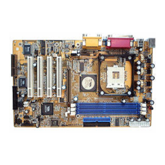
This mainboard uses Award BIOS that enables users to con- BIOS figure many system features including the following: Firmware Power management Wake-up alarms CPU parameters CPU and memory timing The firmware can also be used to set parameters for different processor clock speeds. - Page 10 Table of Mainboard Components Label Component AGP1 Accelerated Graphics Port ATX1 Power connector AUDIO Mic/speaker-out header BAT1 Three volt realtime clock battery CASFAN1 Case fan connector 1 Primary CD-in connector Secondary CD-in connector CNR1 Communications Network Riser (CNR) slot CPU SOCKET Micro PGA 478-pin socket for Pentium 4 CPUs CPUFAN1 Cooling fan for CPU...
-
Page 11: Installing The Mainboard
Installing the Mainboard Follow these safety precautions when installing the mainboard: Wear a grounding strap attached to a grounded device to avoid damage from static electricity. Discharge static electricity by touching the metal case of a safely grounded object before working on the mainboard. Leave components in the static-proof bags they came in. -
Page 12: Installing The Mainboard In A Case
Refer to the following illustration and instructions for installing the mainboard in a case: This illustration shows an ex- 2. Secure the mainboard with ample of a mainboard being screws where appropriate. installed in a tower-type case: Note: Do not overtighten the screws as this can stress the main- board. -
Page 13: Checking Jumper Settings
Checking Jumper Settings The following illustration shows the location of the mainboard jumpers. Pin 1 is labeled. Jumper Settings Jumper Type Description Setting (default) 3-pin Clear CMOS 1-2: Normal jumper 2-3: Clear CMOS 3-pin BIOS flash pro- 1-2: Unprotected tection jumper 2-3: Protected Jumper 1 –... -
Page 14: Connecting Case Components
After you have installed the mainboard into a case, you can begin connecting the mainboard components. Refer to the following: Connect the case power supply connector to ATX1. Connect the CPU cooling fan cable to CPUFAN1. Connect the case cooling fan connector to CASFAN1. -
Page 15: Installing Hardware
LPANEL Device Pins Empty HDD LED (Pins +1, -2) Reset Switch +12, -14 Power Switch +9, -11 Speaker +4, -6, -8, 10 Power LED Power LED -3 (Y), -5 (G), +7 (Pin -3, -5, +7) HDD LED +1, -2 Speaker (Pins +4, -6, -8, 10) Power Switch... -
Page 16: Cpu Installation Procedure
Warning: Overclocking components can adversely affect the reliability of the system and introduce errors into your system. Overclocking can per- manently damage the mainboard by generating excess heat in components that are run beyond the rated limits. This mainboard has a Socket 478 processor socket. When choosing a proc- essor, consider the performance requirements of the system. - Page 17 Swing the locking lever down and hook it under the latch on the edge of the socket. Snap the four retention legs of C ooling Fan the cooling fan into place (see diagram below). Heatsink R etention M odule Swing both lock levers on top of the cooling fan to their opposite sides to secu- re the cooling fan on top of the heatsink.
-
Page 18: Installing Memory Modules
Installing Memory Modules This mainboard accommodates 184-pin 2.5V unbuffered Double Data Rate (DDR) SDRAM memory modules. The memory chips must be standard or registered SDRAM (Synchronous Dynamic Random Access Memory). The memory bus runs at 100 MHz. Installation Procedure The mainboard accommodates three memory modules. -
Page 19: Installing A Hard Disk Drive/Cd-Rom
Installing a Hard Disk Drive/CD-ROM This section describes how to install IDE devices such as a hard disk drive and a CD-ROM drive. About IDE Devices Your mainboard has a primary and secondary IDE channel interface (IDE1 and IDE2). An IDE ribbon cable supporting two IDE devices is bundled with the main- board. -
Page 20: Installing A Floppy Diskette Drive
Installing a CD-ROM/DVD Drive Install the CD-ROM/DVD drive into the drive cage in your system case. Plug the IDE cable into IDE1 (A). If you have already installed an HDD, use the other connec- tor on the IDE cable. Note: Ribbon cable connectors are usually keyed so that they can only be installed correctly on the device connector. -
Page 21: Installing Add-On Cards
Plug a power cable from the case power supply into the power connector on the FDD (C). When you first start up your system, go immediately to the Setup Utility to configure the floppy diskette drives that you have installed. See Standard CMOS Features on page 26 for more information. -
Page 22: Connecting Optional Devices
Connecting Optional Devices Refer to the following for information on connecting the mainboard’s optional devices: LAUDIO: Front panel audio header This header allows the user to install auxiliary front-oriented microphone and line-out ports for easier access. Signal Name Signal Name ACTIVE LINE-OUT (R) ACTIVE LINE-OUT (L) GND (aLO) - Page 23 AUDIO: Front panel MIC/speaker-out header This header allows the user to install auxiliary front-oriented microphone and line-out ports for easier access. Signal Name Signal Name MICIN AGND MICBIAS SPKOUTR XSPKOUTR Empty SPKOUTL XSPKOUTL USB2/USB3: Front panel USB headers The mainboard has two USB ports installed on the rear edge I/O port array. Some computer cases have a special module that mounts USB ports at the front of the case.
- Page 24 Signal Name 5VSB Ground SENSE If you have installed a modem, use the cable provided with the modem to plug into the mainboard WOM1 connector. This enables the Wake On Modem (WOM) feature. When your system is in a power-saving mode, any modem signal automatically resumes the system.
- Page 25 Signal Name EMPTY IRRX GROUND IRTX SJ1: Single color LED header This header allows the user to install an LED indicator to indicate when the computer is in Suspend to RAM (STR) mode or normal mode. Signal Name SUSLED-Y SUSLED-Y PWLED+ LSJ1: Single color LED header This header allows the user to install an LED indicator to indicate when the...
-
Page 26: Connecting I/O Devices
The backplane of the mainboard has the following I/O ports: Parallel port (LPT1) G am e port PS/2 m ouse PS/2 U SB Serial port Serial port M icrophone keyboard ports C OM 1 C OM 2 Line-in Line-out PS/2 Mouse Use the upper PS/2 port to connect a PS/2 pointing device. -
Page 27: External Connector Color Coding
External Connector Color Coding Many connectors now use standard colors as shown in the table below. Connector Color Analog VGA Blue Audio line-in Light blue Audio line-out Lime Digital monitor/flat panel White IEEE 1394 Grey Microphone Pink MIDI/game Gold Parallel Burgundy PS/2-compatible keyboard Purple... -
Page 28: Using Bios
Using BIOS The computer uses the latest Award BIOS with support for Windows Plug and Play. The CMOS chip on the mainboard contains the ROM setup instructions for configuring the mainboard BIOS. The BIOS (Basic Input and Output System) Setup Utility displays the system's configuration status and provides you with options to set system parameters. -
Page 29: Entering The Setup Utility
Entering the Setup Utility When you power on the system, BIOS enters the Power-On Self Test (POST) routines. POST is a series of built-in diagnostics performed by the BIOS. After the POST routines are completed, the following message appears: Press DEL to enter SETUP Pressing the delete key accesses the BIOS Setup Utility: CMOS Setup Utility –... -
Page 30: Using Bios
If your mainboard has an item called Firmware Write Protect in Advanced BIOS features, disable it. (Firmware Write Protect prevents BIOS from being overwritten.) Create a bootable system disk. (Refer to Windows online help for infor- mation on creating a bootable system disk.) Download the Flash Utility and new BIOS file from the manufacturer's Web site. -
Page 31: Standard Cmos Features
Standard CMOS Features This option displays basic information about your system. CMOS Setup Utility – Copyright (C) 1984 – 2001 Award Software Standard CMOS Features Item Help Date (mm:dd:yy) Tue, July 11 2001 Time (hh:mm:ss) 12 : 8 : 59 Menu Level IDE Primary Master Change the day, month,... - Page 32 IDE HDD Auto-Detection Press <Enter> while this item is highlighted to prompt the Setup Utility to automatically detect and configure an IDE device on the IDE channel. Note: If you are setting up a new hard disk drive that supports LBA mode, more than one line will appear in the parameter box.
-
Page 33: Advanced Bios Setup Option
Advanced BIOS Setup Option This option defines advanced information about your system. CMOS Setup Utility – Copyright (C) 1984 – 2001 Award Software Advanced BIOS Features Item Help Anti-Virus Protection [Disabled] CPU L1 & L2 Cache [Enabled] Menu Level CPU L2 Cache ECC Checking [Enabled] Quick Power On Self Test [Enabled]... - Page 34 Quick Power On Self Test (Enabled) Enable this item to shorten the power on testing (POST) and have your sys- tem start up faster. You might like to enable this item after you are confident that your system hardware is operating smoothly. First/Second/Third Boot Device (Floppy/HDD-0/CDROM) Use these three items to select the priority and order of the devices that your...
-
Page 35: Advanced Chipset Features Option
S.M.A.R.T. software resides on both the disk drive and the host computer. The disk drive software monitors the internal performance of the motors, me- dia, heads, and electronics of the drive. The host software monitors the overall reliability status of the drive. If a device failure is predicted, the host software, through the Client WORKS S.M.A.R.T applet, warns the user of the impending condition and advises appropriate action to protect the data. - Page 36 DRAM Clock/Drive Control Scroll to this item and press <Enter> to view the following screen: CMOS Setup Utility – Copyright (C) 1984 – 2001 Award Software DRAM Clock/Drive Control Item Help Current FSB Frequency Current DRAM Frequency Menu Level DRAM Clock [By SPD] DRAM Timing [Manual]...
- Page 37 Precharge to Active (3T) This item is used to designate the minimum Row Precharge time of the SDRAM devices on the module. DRAM must continually be refreshed or it will lose its data. Normally, DRAM is refreshed entirely as the result of a single request. This option allows you to de- termine the number of CPU clocks allocated for the Row Address Strobe (RAS) to accumulate its charge before the DRAM is refreshed.
- Page 38 for graphics memory. We recommend that you leave this item at the default value. AGP Mode (4X) This item allows you to enable or disable the caching of display data for the processor video memory. Enabling AGP-4X Mode can greatly improve the display speed.
-
Page 39: Integrated Peripherals Option
writes are not buffered and the CPU must wait until the write is complete be- fore starting another write cycle. PCI Master 0 WS Write (Enabled) When enabled, writes to the PCI bus are executed with zero wait states. PCI Delay Transaction (Enabled) The mainboard’s chipset has an embedded 32-bit post write buffer to support delay transactions cycles. - Page 40 VIA OnChip IDE Device Scroll to this item and press <Enter> to view the following screen: CMOS Setup Utility – Copyright (C) 1984 – 2001 Award Software VIA OnChip IDE Device Item Help OnChip IDE Channel0 [Enabled] OnChip IDE Channel1 [Enabled] Menu Level IDE Prefetch Mode...
- Page 41 VIA OnChip PCI Device Scroll to this item and press <Enter> to view the following screen: CMOS Setup Utility – Copyright (C) 1984 – 2001 Award Software VIA OnChip PCI Device Item Help VIA-3058 AC97 Audio [Auto] VIA-3068 MC97 Modem [Auto] Menu Level : Move...
- Page 42 Onboard FDC Controller (Enabled) This option enables the onboard floppy disk drive controller. Onboard Serial Port 1 (3F8/IRQ4) This option is used to assign the I/O address and address and interrupt re- quest (IRQ) for onboard serial port 1 (COM1). Onboard Serial Port 2 (2F8/IRQ3) This option is used to assign the I/O address and address and interrupt re- quest (IRQ) for onboard serial port 2 (COM2).
-
Page 43: Power Management Setup Option
Midi Port IRQ (10) This item sets the interrupt request for the Midi function. Press <Esc> to return to the Integrated Peripherals screen. Init Display First (PCI Slot) Use this item to specify whether your graphics adapter is installed in one of the PCI slots or is integrated on the mainboard. - Page 44 Wake Up Calls If the system is suspended, or has been powered down by software, it can be resumed by a wake up call that is generated by incoming traffic to a modem, a LAN card, a PCI card, or a fixed alarm on the system realtime clock, CMOS Setup Utility –...
- Page 45 Video Off Method (DPMS Support) This item defines how the video is powered down to save power. This item is set to DPMS (Display Power Management Software) by default. MODEM Use IRQ (3) If you want an incoming call on a modem to automatically resume the system from a power-saving mode, use this item to specify the interrupt request line (IRQ) that is used by the modem.
- Page 46 LPT & COM (LPT/COM ) When this item is enabled, the system will restart the power-saving timeout counters when any activity is detected on the serial ports, or the parallel port. HDD & FDD (ON) When this item is enabled, the system will restart the power-saving timeout counters when any activity is detected on the hard disk drive or the floppy diskette drive.
-
Page 47: Pnp/Pci Configuration Option
Press <Esc> to return to the previous screen. PNP/PCI Configuration Option These options configure how PnP (Plug and Play) and PCI expansion cards oper- ate in your system. Both the ISA and PCI buses on the Mainboard use system IRQs (Interrupt ReQuests) and DMAs (Direct Memory Access). You must set up the IRQ and DMA assignments correctly through the PnP/PCI Configurations Setup utility for the mainboard to work properly. - Page 48 item to Manual, and then opening up the IRQ Resources and Memory Re- sources submenus. IRQ Resources The submenu allows you to individually assign an interrupt type for interrupts IRQ-3 to IRQ-15. CMOS Setup Utility – Copyright (C) 1984 – 2001 Award Software PnP/PCI Configurations Item IRQ-3 assigned to...
-
Page 49: Pc Health Status Option
PC Health Status Option On mainboards that support hardware monitoring, this item lets you monitor the parameters for critical voltages, critical temperatures, and fan speeds: CMOS Setup Utility – Copyright (C) 1984 – 2001 Award Software PC Health Status Item Help Shutdown Temperature [Disabled] CPU VCORE... -
Page 50: Frequency/Voltage Control
Frequency/Voltage Control This item enables you to set the clock speed and system bus for your system. The clock speed and system bus are determined by the kind of processor you have installed in your system. CMOS Setup Utility – Copyright (C) 1984 – 2001 Award Software Frequency/Voltage Control Item Help CPU Ratio... -
Page 51: Load Fail-Safe Defaults Option
Load Fail-Safe Defaults Option This option opens a dialog box that lets you install fail-safe defaults for all ap- propriate items in the Setup Utility: Press <Y> and then <Enter> to install the defaults. Press <N> and then <En- ter> to not install the defaults. The fail-safe defaults place no great demands on the system and are generally stable. -
Page 52: Save & Exit Setup Option
Save & Exit Setup Option Highlight this item and press <Enter> to save the changes that you have ma- de in the Setup Utility and exit the Setup Utility. When the Save and Exit dialog box appears, press <Y> to save and exit, or press <N> to return to the main menu: Exit Without Saving Highlight this item and press <Enter>... -
Page 53: Using The Mainboard Software
Using the Mainboard Software The support software CD-ROM that is included in the mainboard package contains all the drivers and utility programs needed to properly run the bun- dled products. Below you can find a brief description of each software program, and the location for your mainboard version. -
Page 54: Drivers Installation
Audio Drivers and Software Most of the sub-folders in this folder are empty, with a short README file giv- ing directions to alternate folders for the appropriate software. Installation for Windows 2000/98/98SE/ME/95 To install the audio drivers, go the directory \VIA\8233ac97\ then run SETUP.EXE. -
Page 55: Award Flash Memory Utility
Award Flash Memory Utility This utility lets you erase the system BIOS stored on a Flash Memory chip on the mainboard, and lets you copy an updated version of the BIOS to the chip. Proceed with caution when using this program. If you erase the current BIOS and fail to write a new BIOS, or write a new BIOS that is incorrect, your sys- tem will malfunction. -
Page 56: Manual Installation
Language Genius The Language Genius is a software –based product that helps you to learn new languages. To install the Language Genius software program run SETUP.EXE from the following directory: \UTILITY\LANGUAGE GENIUS\ENG\LANGUAGEGENIUS PageABC The PageABC application software enables you to create your very own home page.
Need help?
Do you have a question about the MS9107C and is the answer not in the manual?
Questions and answers