Table of Contents
Advertisement
Quick Links
Advertisement
Table of Contents

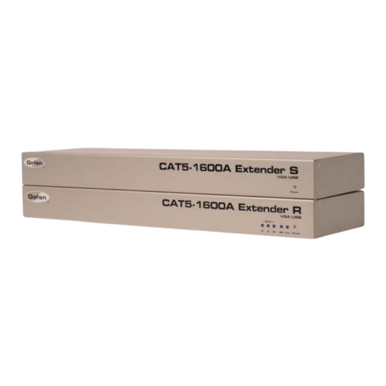
Summary of Contents for Gefen EXT-CAT5-1600A
- Page 1 ® CAT5-1600A Extender EXT-CAT5-1600A User Manual www.gefen.com...
- Page 2 Notice Gefen, LLC reserves the right to make changes in the hard ware, packaging and any accompanying doc u men ta tion without prior written notice. CAT5-1600A Extender is a trademark of Gefen, LLC © 2011, Gefen, LLC. All rights reserved.
-
Page 3: Table Of Contents
CONTENTS Introduction Operation Notes Features Sender Unit Layout Sender Unit Descriptions Receiver Unit Layout Receiver Unit Descriptions Connecting the CAT5-1600A Extender DIP Switch Configuration 12 Network Cable Wiring Diagram 13 Specifi cations 14 Warranty... -
Page 4: Introduction
The Gefen CAT5-1600A Extender The Gefen CAT5-1600A extends VGA, Audio, and USB up to 330 feet (100 me- ters) using CAT-5 cables. Display resolutions up to 1920x1200 are supported. A local monitor can be connected to the Sender unit and up to two monitors can be connected to the Receiver unit. -
Page 5: Operation Notes
OPERATION NOTES READ THESE NOTES BEFORE OPERATING THE CAT5-1600A EXTENDER • The CAT5-1600A extends VGA and Audio up to 1000 feet (300 meters). • CAT-5 cables should not exceed 330 feet (100 meters) when extending USB. -
Page 6: Features
FEATURES Features • Extends analog video (VGA) and analog audio up to 1000 ft. (300 meters) over two CAT-5 cables. • Extends USB 2.0 up to 330 feet (100 meters) • Supports resolutions up to 1920 x 1200 • Supports USB 2.0 at up to 480 Mbps transfer rate •... -
Page 7: Sender Unit Layout
SENDER UNIT LAYOUT... -
Page 8: Sender Unit Descriptions
SENDER UNIT DESCRIPTIONS Power Indicator This LED will turn RED once the locking power supply has been properly connected. When the CAT-5 link is established between the Sender and Receiver units, the LED will be GREEN. When the Sender unit is in Standby Mode or Power Saving Mode, this LED will be RED. -
Page 9: Receiver Unit Layout
RECEIVER UNIT LAYOUT... -
Page 10: Receiver Panel Descriptions
(available at electronics stores). Use gentle force when rotating Trim Pot controls. Turn controls in both directions if necessary to get best results. Never force a control if resistance is encountered. Gefen is not responsible for inoperable units due to broken trim pot controls. -
Page 11: Connecting The Cat5-1600A Extender
(Up To 1,000 feet) AUDIO CABLE Computer USB CABLE Receiver Powered Local VGA Monitor Speakers Sender USB Mouse USB Keyboard VGA Monitor VGA Monitor EXT-CAT5-1600A USB External HDD USB Printer ATTENTION: This product should always be connected to a grounded electrical socket. -
Page 12: Dip Switch Configuration
DIP SWITCH CONFIGURATION Sender Unit The CAT5-1600A contains two (2) DIP switches on the bottom of the Sender Unit and the Receiver Unit. The follow information outlines the functionality of each DIP switch: The two DIP switches on the bottom of the Sender Unit. DIP Switch 1 - Green Mode (Default = ON) •... - Page 13 DIP SWITCH CONFIGURATION Receiver Unit The CAT5-1600A Receiver Unit contains two (2) DIP switches on the bottom of the unit. A single trim pot (potentiometer) is also located next to the DIP switch bank. The follow information outlines the functionality of each DIP switch and the trim pot: The two DIP switches and single trim pot on the bottom of the...
- Page 14 DIP SWITCH CONFIGURATION DIP Switch 2 - EDID Mode (Default = OFF) • OFF - Pass-Through Mode If DIP switch 2 is OFF, then the downstream EDID information is copied to the input. • ON - Local EDID When DIP switch 2 is set to the ON position, then the EDID is copied from the Local Monitor output on Sender Unit.
-
Page 15: Network Cable Wiring Diagram
NETWORK CABLE WIRING DIAGRAM Gefen recommends the TIA/EIA-568-B wiring option. Please adhere to the table below when fi eld-terminating the CAT-5 cable for use with Gefen products. Color Orange / White Orange Green / White Blue Blue / White Green... -
Page 16: Specifi Cations
SPECIFICATIONS Video Amplifi er Bandwidth ............... 350 MHz Horizontal Frequency Range ............15 kHz - 70 kHz Vertical Frequency Range ............30 kHz - 170 kHz Video Input Connector (Sender)........... (1) VGA HD-15, male Video Monitor Output Connector (Sender)......(1) VGA HD-15, female Video Output Connectors (Receiver)......... -
Page 17: Warranty
Gefen warrants the equipment it manufactures to be free from defects in material and workmanship. If equipment fails because of such defects and Gefen is notifi ed within two (2) years from the date of shipment, Gefen will, at its option, repair or replace the equipment, provided that the equipment has not been subjected to mechanical, electrical, or other abuse or modifi... - Page 19 Rev A6 20600 Nordhoff St., Chatsworth CA 91311 1-800-545-6900 818-772-9100 fax: 818-772-9120 www.gefen.com support@gefen.com This product uses UL listed power supplies.


Need help?
Do you have a question about the EXT-CAT5-1600A and is the answer not in the manual?
Questions and answers