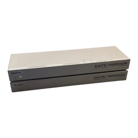
Summary of Contents for Gefen EXT-CAT5-1500HD
- Page 1 ® User Manual www.gefen.com...
- Page 2 Notice Gefen LLC reserves the right to make changes in the hard ware, packaging and any accompanying doc u men ta tion without prior written notice. CAT5-1600HD is a trademark of Gefen LLC © 2010 Gefen LLC, All Rights Reserved...
-
Page 3: Table Of Contents
CONTENTS Introduction Features Connecting The CAT5-1600HD Sender Panel Layout Sender Panel Descriptions Receiver Panel Layout Receiver Panel Descriptions Specifi cations Warranty... -
Page 4: Introduction
Gefen Gefen is a unique product line catering to the growing needs for innovative home theater solutions. We specialize in total integration for your home theater, while also focusing on going above and beyond customer expectations to ensure you get the most from your hardware. -
Page 5: Features
FEATURES Features • Extends any DVI compliant device up to 200 feet (60 meters) from the computer at up to 1920x1200 • Extends USB 2.0 compliant devices up to 300 feet • DVI is transmitted digitally for zero signal loss over CAT-5 cable •... -
Page 6: Connecting The Cat5-1600Hd
CONNECTING THE CAT5-1600HD How to Connect the CAT5-1600HD Connect the Sender unit to the computer via the included DVI and USB cables. At the remote location, connect the display, mouse, keyboard, printer and any other USB accessory to the Receiver unit (up to 4 USB devices may be connected at one time to the Receiver unit). -
Page 7: Sender Panel Layout
SENDER PANEL LAYOUT Front Panel Back Panel... -
Page 8: Sender Panel Descriptions
SENDER PANEL DESCRIPTIONS HPD LED This LED shows the status of the Hot Plug Detect signal being sensed at the Receiver. When this LED is lit, a compatible DVI display device is connected to the Receiver and operating properly. Power LED When this LED is lit, power is correctly supplied to the unit. -
Page 9: Receiver Panel Layout
RECEIVER PANEL LAYOUT Front Panel Back Panel... -
Page 10: Receiver Panel Descriptions
RECEIVER PANEL DESCRIPTIONS DDC Lock LED When this LED is lit, the quality of the data transmission between Sender and Receiver is stable. The HDCP copy-protection signal is being passed from the host computer to the remote Display, allowing the viewing of protected source content (Blu-ray discs and movies for instance). -
Page 11: Specifi Cations
SPECIFICATIONS Video Amplifi er Bandwidth.................165 MHz Single Link Range..............1080P, 1920 x 1200 Input Video Signal................1.2 volts p-p Input DDC Signal................5 volts p-p (TTL) DVI Connector.......DVI-I (29 pin) female (DVI-D digital signal only) USB Input (Sender)............USB type “B” connector USB Output (Receiver)..........four USB type “A” connectors Link Connectors (2).................RJ-45 Shielded Power Supply.................5V DC / 2A each Power Consumption..........10 Watts (max) per power supply...


Need help?
Do you have a question about the EXT-CAT5-1500HD and is the answer not in the manual?
Questions and answers