Gefen CAT5 User Manual
Cat5-7500hd series
Hide thumbs
Also See for CAT5:
- User manual (20 pages) ,
- Quick start manual (2 pages) ,
- User manual (10 pages)
Table of Contents
Advertisement
Quick Links
Download this manual
See also:
User Manual
Advertisement
Table of Contents

Summary of Contents for Gefen CAT5
- Page 1 CAT5 • 7500HD U S E R M A N U A L www.gefen.com...
- Page 2 6265 Variel Ave. Woodland Hills, CA 91367-9897 Notice Gefen Inc. reserves the right to make changes in the hard ware, packaging and any accompanying doc u men ta tion without prior written notice. CAT5•7500HD is a trademark of Gefen Inc.
-
Page 3: Table Of Contents
CAT5•7500HD Front Panel Descriptions CAT5•7500HDS Back Panel Layout CAT5•7500HDS Back Panel Functions CAT5•7500HDR Back Panel Layout CAT5•7500HDR Back Panel Functions CAT5•7500HD - Wiring Diagram CAT5 Link Cable Wiring Diagram Service Switch Usage Guide Frequently Asked Questions Terminology System Specifi cations Warranty... -
Page 4: Operation Notes
Thank you for purchasing the new ex•tend•it CAT5•7500HD series by Gefen, Inc. The ex•tend•it CAT5•7500HD by Gefen allows users the benefi ts of extending USB, audio in, audio out, PS/2, RS232, and video signals beyond the desktop. In a growing number of applications, broadcast stations and production facilities there is a need to locate a computer remotely, from the keyboard, mouse, and video monitor. -
Page 5: How It Works
The CAT5•7500HDR receiver unit is placed next to the monitors, keyboard, mouse, and USB peripherals at the remote location. The monitor and keyboard are connected to the CAT5•7500HDR, similar to the way they are con nect ed to the back of the computer (PC or Macintosh). -
Page 6: Cat5•7500Hd Front Panel Descriptions
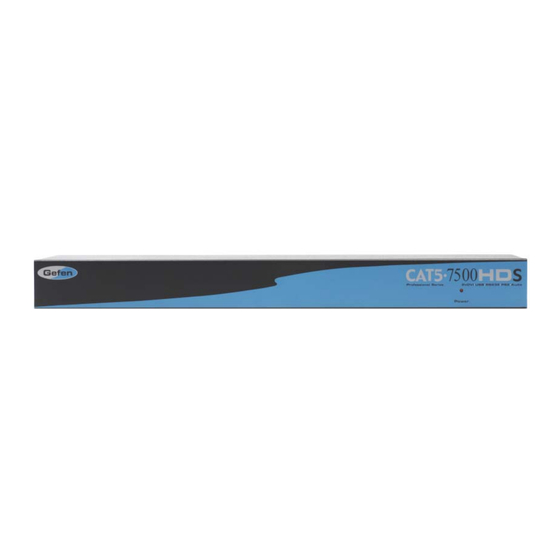
CAT5•7500HDS FRONT PANEL DE SCRIP TIONS Front Panel Function Descriptions Power On Indication - Indicates that the unit is on and plugged in. CAT5•7500HDR FRONT PANEL LAYOUT Front Panel Function Descriptions POWER ON INDICATOR - Indicates that the unit is on and plugged in. -
Page 7: Cat5•7500Hds Back Panel Layout
CAT5•7500HDS BACK PANEL LAYOUT... - Page 8 CAT5•7500HDS BACK PANEL LAYOUT POWER - 5 VDC external power supply CAT5 Video 1 - RJ-45 input extends DVI input 1 with CAT-5 cable CAT5 USB/DDC1 - RJ-45 input extends USB and DDC1 signals with CAT-5 cable DVI IN 1 - DVI Input connects to your computer with the supplied DVI cable...
-
Page 9: Cat5•7500Hdr Back Panel Layout
CAT5•7500HDR BACK PANEL LAYOUT... -
Page 10: Cat5•7500Hdr Back Panel Functions
CAT5•7500HDR BACK PANEL FUNC TIONS POWER - 5 VDC external power supply CAT5 USB/DDC1 - RJ-45 input extends USB and DDC1 signals with CAT-5 cable CAT5 Video 1 - RJ-45 input extends video input 1 with CAT-5 cable DVI OUT 1 - DVI output connects to the monitor 1 for local video... -
Page 11: Cat5•7500Hd Wiring Diagram
CAT5•7500HD WIRING DIAGRAM... -
Page 12: Cat5 Link Cable Wiring Diagram
CAT5 LINK CABLE - WIRING DIAGRAM... -
Page 13: Service Switch Usage Guide
For the CAT5•7500HD, there are 1 set of switches for each monitor under both the sender and receiver units. The switches are hidden beneath black stickers. -
Page 14: Frequently Asked Questions
I’m getting no video on the screens, what can I check? First thing to check is make sure that the video CAT5 is linked to the other video CAT5 port and the same with the DDC ports. Test to make sure the units are working with short CAT-5e cables 15-20 feet. -
Page 15: Terminology
TERMINOLOGY CAT-5 Category 5 cable, commonly known as Cat 5, is an unshielded twisted pair type cable designed for high signal integrity. The actual standard defi nes specifi c electrical properties of the wire, but it is most commonly known as being rated for its Ethernet capability of 100 Mbit/s. - Page 16 SPECIFICATIONS Video Amplifi er Bandwidth ................1.65 GHz Single Link Range ................1080p / 1920 x 1200 Input Video Signal ..................1.2 volts p- Input DDC Signal .................. 5 volts p-p (TTL) DVI Output Connector Type ........DVI-I (29 pin) female (digital only) Link Connector ..................
-
Page 17: Warranty
Gefen Inc. warrants the equipment it manufactures to be free from defects in material and workmanship. If equipment fails because of such defects and Gefen Inc. is notifi ed within two (2) year from the date of shipment, Gefen Inc. will, at its option, repair or replace the equipment, provided that the equipment has not been subjected to mechanical, electrical, or other abuse or modifi... - Page 18 6265 Variel Avenue Woodland Hills, CA 91367 1-800-545-6900 818-884-6294 fax: 818-884-3108 www.gefen.com gsinfo@gefen.com...


Need help?
Do you have a question about the CAT5 and is the answer not in the manual?
Questions and answers