Table of Contents
Advertisement
Quick Links
Advertisement
Table of Contents

Summary of Contents for Gefen CAT5-1500
- Page 1 ® CAT5•1500 E X T - C A T 5 - 1 5 0 0 U S E R M A N U A L www.gefen.com...
- Page 2 Notice Gefen Inc. reserves the right to make changes in the hard ware, packaging and any accompanying doc u men ta tion without prior written notice. CAT5•1500 is a trademark of Gefen Inc. © 2009 Gefen Inc., All Rights Reserved...
-
Page 3: Table Of Contents
TABLE OF CONTENTS Introduction Box Contents How it works Operation Notes CAT5•1500 Front Panel Layouts CAT5•1500S Send Unit Back Panel CAT5•1500S Back Panel Function Descriptions CAT5•1500R Back Panel Layout CAT5•1500R Back Panel Functions CAT5 Cable Length Setup Link Cable - Wiring Diagram CAT5•1500 Wiring Diagram System Specifi... -
Page 4: Introduction
INTRODUCTION Thank you for purchasing the new ex•tend•it CAT5•1500 series. The ex•tend•it CAT5•1500 allows users the benefi ts of extending VGA, USB, and audio signals beyond the desktop. In a growing number of applications, broadcast stations and production facilities there is a need to control a computer remotely. The keyboard, mouse, and video monitor are relocated to the remote side. -
Page 5: Box Contents
BOX CONTENTS The CAT5•1500 system consists of: (1) CAT5•1500S sender unit (1) CAT5•1500R receiver unit (2) 5 VDC power supply (1) Video cable (6 FT) (1) USB cable (6 FT) (1) Audio cable (6 FT) (1) User Manual... -
Page 6: How It Works
HOW IT WORKS In its most basic application, the CAT5•1500S sender unit resides next to the computer. With the supplied VGA, USB, and audio cables, they connect the computer to the CAT5•1500S sender unit. The CAT5•1500R receiver unit and USB peripherals are placed next to the mon i- tor. -
Page 7: Operation Notes
OPERATION NOTES READ THESE NOTES BEFORE IN STALL ING OR OPERATING THE CAT5•1500 SYSTEM * Industry standard Category-5 (CAT-5) cables are used to link the CAT5•1500 sender and receiver boxes together. * When two monitors are used in the local and remote lo ca tions, the video monitors must be a multi-resolution type. -
Page 8: Cat5•1500 Front Panel Layouts
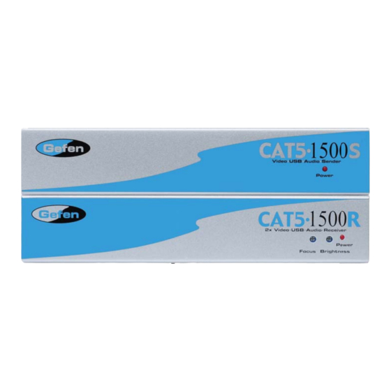
CAT5•1500S FRONT PANEL LAY OUT Front Panel Function Descriptions POWER ON INDICATOR - Indicates that the unit is plugged in and powered on CAT5•1500R FRONT PANEL LAYOUT Front Panel Function Descriptions Focus - Fine focus adjustment for video BRIGHTNESS - Adjusts the video brightness POWER ON INDICATOR - The red LED indicates that the unit is powered on... -
Page 9: Cat5•1500S Send Unit Back Panel
CAT5•1500S SEND UNIT BACK PANEL... - Page 10 CAT5•1500S BACK PANEL FUNCTIONS POWER - 5 VDC external power supply MONITOR OUT - HD15 output connects to the monitor for local video VIDEO IN - HD15 input from computer CAT-5 VIDEO - RJ-45 input extends VGA signals with CAT-5 cable CAT-5 USB/AUD - RJ-45 input extends USB, and audio signals with CAT-5 cable AUDIO - Audio mini Jack input from computer USB IN - USB Input from computer...
-
Page 11: Cat5•1500R Back Panel Layout
CAT5•1500R BACK PANEL LAYOUT... -
Page 12: Cat5•1500R Back Panel Functions
CAT5•1500R BACK PANEL FUNC TIONS POWER - 5 VDC external power supply VIDEO OUT 1 - HD15 output connecting to the video monitor VIDEO OUT 2 - HD15 output connecting to the video monitor (mirrored video) AUDIO - Audio Mini Jack CAT-5 VIDEO - RJ-45 input connects CAT-5 cable to receive extended VGA signals CAT-5 USB/AUD - RJ-45 input connects CAT-5 cable to receive extended USB,... -
Page 13: Cat5 Cable Length Setup
CAT5 CABLE LENGTH SETUP Jumper settings are used to set the focus of the picture and characters to the best possible sharpness. The jump ers in the CAT5•1500R are set at the factory as shown in the diagram below. The fi rst step to adjusting the video is to have the CAT5•1500S and CAT5•1500R con nect ed together with the CAT-5 cable that is going to be used in the in stal la tion. -
Page 14: Link Cable - Wiring Diagram
LINK CABLE - WIRING DIAGRAM... -
Page 15: Cat5•1500 Wiring Diagram
CAT5•1500 WIRING DIAGRAM... - Page 16 SPECIFICATIONS Video Amplifi er Bandwidth .................. 350 MHz Actual Bandwidth .........,............120 MHz Input Video Signal ..................1.2 Volts p-p Input Sync Signal ................... 5 Volts p-p (TTL) Horizontal Frequency Range ................15-70 KHz Vertical Frequency Range ................30 - 170 Hz Video In........................
-
Page 17: Warranty
If equipment fails because of such defects and Gefen Inc. is notifi ed within two (2) year from the date of shipment, Gefen Inc. will, at its option, repair or replace the equipment, provided that the equipment has not been subjected to mechanical, electrical, or other abuse or modifi... - Page 19 Rev X1 20600 Nordhoff St Chatsworth, CA 91311 1-800-545-6900 818-772-9100 fax: 818-772-9120 www.gefen.com support@gefen.com...


Need help?
Do you have a question about the CAT5-1500 and is the answer not in the manual?
Questions and answers