
Related Manuals for Rose electronics CrystalView Extreme


Summary of Contents for Rose electronics CrystalView Extreme
- Page 1 CrystalView Extreme LAN Extender INSTALLATION AND OPERATIONS MANUAL Part Number CRK-1DTXT-EX45/A1 10707 Stancliff Road Phone: (281) 933-7673 Houston, Texas 77099 WWW.ROSE.COM...
- Page 2 Limited Warranty Rose Electronics warrants the CrystalView Extreme to be in good working order for one year from the date of purchase from Rose Electronics or an authorized dealer. Should this product fail to be in good working order at any time during this one-year warranty period, Rose Electronics will, at its option, repair or replace the Unit as set forth below.
- Page 3 FCC/IC STATEMENTS, EU DECLARATION OF CONFORMITY FCC Radio Frequency Interference This device complies with Part 15 of the FCC rules; operation is subject to the following two conditions: 1. This device may not cause harmful interference 2. This device must accept any interference received, including interference that may cause undesired operation.
-
Page 4: Table Of Contents
Disclaimer ...................... 1 System Introduction ..................1 Features ......................2 Package Contents ..................3 Additional Installation Items ................3 Rose Electronics web site................3 Product Registration ..................3 System Overview ................... 4 Models ......................5 Transmitter - Front Panel ................6 Transmitter - Rear panel Connectors ............ -
Page 5: Disclaimer
Receiver or a Receiver paired to a different Transmitter, see Attachment C for instructions. The CrystalView Extreme extender supports all USB 2.0 devices. It is ideal for use in industrial control areas, digital signage, connecting LAN cameras for security systems, USB device printing, scanning and storage. -
Page 6: Features
3. Connect the Transmitter and Receiver to your network using standard CAT5 cable 4. Apply power and the installation is complete. The Transmitter unit requires a +5VDC power adapter (included). The Receiver unit requires a +24VDC power adapter (included). CrystalView Extreme Installation and Operations Manual... -
Page 7: Package Contents
Rose Electronics web site Visit our web site at www.rose.com for additional information on the CrystalView Extreme and other products offered by Rose Electronics that are designed for data center applications, classroom environments, digital wall/signage displays, industrial / military systems, and many other access and switching applications. -
Page 8: System Overview
OVERVIEW System Overview The CrystalView Extreme is a very versatile and flexible system that can be easily and quickly installed. You can position your computer anywhere on your LAN and access it over your network from anywhere you install the matched Receiver. -
Page 9: Models
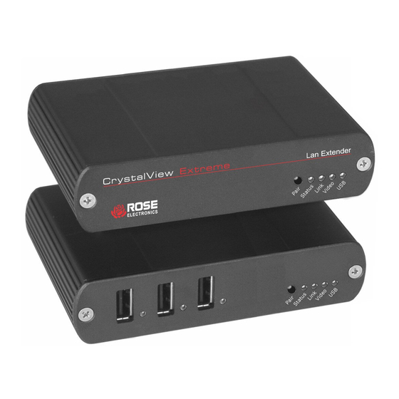
Receiver – Front View Indicators Pair Status Link Video Connectors USB Type A (3) Receiver – Rear View Connectors DVI-D Out Headphone Out Microphone In Config Link Power (+24V / 1A) Figure 1. Models CrystalView Extreme Installation and Operations Manual... -
Page 10: Transmitter - Front Panel
Reserved for company use only USB Type B USB input from Host computer (Supplied) Link (RJ45) Connection for a CAT5 or better cable to the Receiver unit Power +5V, 3A power adapter (Supplied) Table 1. Transmitter Indicators/Connectors CrystalView Extreme Installation and Operations Manual... -
Page 11: Receiver - Front Panel
Connects to a 3.5mm microphone cable Config Reserved for company use only Link (RJ45) Connection for a CAT5 or better cable to the Transmitter unit Power +24V, 1A power adapter (Supplied) Table 2. Receiver Indicators / Connectors CrystalView Extreme Installation and Operations Manual... -
Page 12: System Installation
INSTALLATION System Installation Before installing the CrystalView Extreme, pre-plan the layout of the computer, the Transmitter, the Receiver, and the equipment that will be connected to the Receiver. The Transmitter and Receiver units should be in a location that is easily accessible to your corporate LAN ports. -
Page 13: Receiver Installation
Verify that the LEDs are registering properly. (Refer to Table 2 and Table 3) If the Link LED is off, your network may not allow the CrystalView Extreme to pass the MAC address of the units through your network. Check this with your network administrator. -
Page 14: Connecting Usb Devices
If the total power is greater than 500ma, use a powered Hub to supplement the power to the devices. The CrystalView Extreme is compatible with a wide variety or graphic cards, monitors, USB devices, and operating systems. See Appendix B for a list of tested devices. -
Page 15: System Troubleshooting
6. Reconnect the Transmitter to the computer If the USB LED is still off, contact Technical support Video LED blinking amber and the monitor is black Host computer resolution is not compatible with the CrystalView Extreme units. 1. Disconnect all USB devices from the Receiver 2. - Page 16 Resolution is not supported (See Appendix B) The CrystalView Extreme Transmitter and Receiver indicators will provide information about the operation, connectivity and data transmission. Observe these indicators and refer Table 1 and Table 2 for a description of the indicator states.
-
Page 17: Product Safety
The CrystalView Extreme extender has been tested for conformance to safety regulations and requirements, and has been certified for international use. Like all electronic equipment, the CrystalView Extreme should be used with care. To protect yourself from possible injury and to minimize the risk of damage to the Unit, read and follow these safety instructions. -
Page 18: Maintenance And Repair
This Unit does not contain any internal user-serviceable parts. In the event a Unit needs repair or maintenance, you must first obtain a Return Authorization (RA) number from Rose Electronics or an authorized repair center. This Return Authorization number must appear on the outside of the shipping container. -
Page 19: Appendix A - General Specifications
-20 to 70 C Operating Humidity 20% to 80% non-condensing Storage Humidity 10% to 90% non-condensing ESD rating EMC EN-6100-4-2 4kV Contact, 8kV Air Regulatory Testing FCC Part 15 Class A, CE, ICE20030 Class A CrystalView Extreme Installation and Operations Manual... -
Page 20: Appendix B - Compatibility
Appendix B – Compatibility The CrystalView Extreme is compatible with many graphic cards, monitors, mice, keyboards, monitors, and USB devices. With so many variations of keyboards, mice, and USB devices, Rose Electronics can not guarantee that all peripherals will function properly. Monitors •... -
Page 21: Appendix C - Pairing Transmitter And Receiver
Appendix C – Pairing Transmitter and Receiver The CrystalView Extreme Transmitter and Receiver are paired at the factory to allow communication between them over your LAN. No additional configuration is normally needed. If the Transmitter or Receiver unit needs to be paired to another Transmitter or Receiver, perform the below steps to pair the Transmitter and Receiver units. - Page 22 NOTES CrystalView Extreme Installation and Operations Manual...
- Page 24 10707 Stancliff Road Phone: (281) 933-7673 Houston, Texas 77099 WWW.ROSE.COM...
Need help?
Do you have a question about the CrystalView Extreme and is the answer not in the manual?
Questions and answers