L.B. White Premier TS350 Owner's Manual And Instructions
Premier tent heaters
Hide thumbs
Also See for Premier TS350:
- Owner's manual and instructions (132 pages) ,
- Owner's manual and instructions (33 pages)
Table of Contents
Advertisement
Owner's Manual and Instructions
Congratulations!
You have purchased the finest circulating tent heater available.
Your new L.B. White heater incorporates the benefits from the most experienced
manufacturer of heating products using state-of-the-art technology.
We, at L.B. White, thank you for your confidence in our products and welcome
any suggestions or comments you may have...call us, toll-free, at 1-800-345-7200.
ATTENTION ALL USERS
This heater has been tested and evaluated by C.S.A. International in
accordance with the requirements of Standard ANSI Z83.7 CSA 2.14 and is
listed and approved as a ductable direct gas-fired forced-air construction heater
with application for the temporary heating of buildings under construction,
alteration, or repair. Additionally, this heater has been application reviewed and
approved by C.S.A. International for USA Tent Heating Applications with
temporary human occupancy. If you are considering using this product for any
application other than its intended use, then please contact your fuel gas
supplier, or the L.B. White Co., Inc.
MODELS
OUTPUT (Btuh)
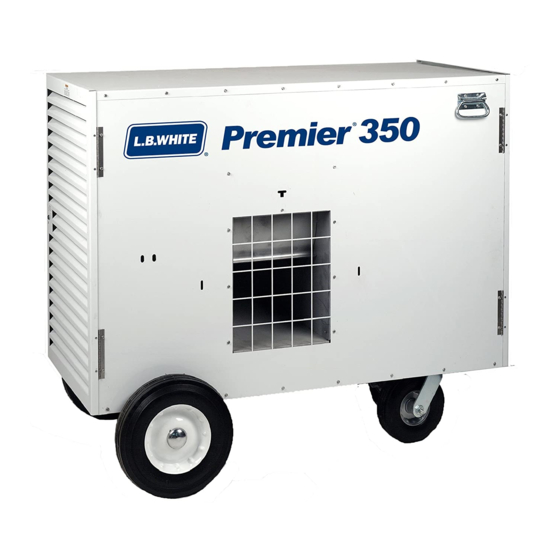
TS350
350,000
Certification by:
Premier Tent Heaters
FUEL
Propane Vapor
Withdrawal
or
Natural Gas
150-22918-E
Advertisement
Table of Contents
Troubleshooting

Related Manuals for L.B. White Premier TS350


Summary of Contents for L.B. White Premier TS350
- Page 1 Your new L.B. White heater incorporates the benefits from the most experienced manufacturer of heating products using state-of-the-art technology. We, at L.B. White, thank you for your confidence in our products and welcome any suggestions or comments you may have...call us, toll-free, at 1-800-345-7200.
- Page 3 Save this Owner’s Manual for future use and reference. Owner’s Manuals and replacement labels are available at no charge. For assistance, contact L.B. White at 1-800-345-7200. WARNING Proper gas supply pressure must be provided to the inlet of the heater.
-
Page 4: Table Of Contents
Table of Contents SECTION PAGE General Information ..............4 Heater Specifications . -
Page 5: General Information
Have your qualified installer review this manual with you so that you fully understand the heater and how it The L.B. White Co., Inc. has a policy of continuous product functions. improvement. It reserves the right to change specifications and design without notice. -
Page 6: Safety Precautions
Safety Precautions WARNING Asphyxiation H H azard Do not use this heater for heating human living Owner’s Manual, heater dataplate, or contact the L.B. quarters. White Company to determine combustion air ventilation requirements of the heater. Do not use in unventilated areas. Lack of proper ventilation air will lead to improper The flow of combustion and ventilation air must not be combustion. - Page 7 11. Always turn off the gas supply to the heater if the heater is not going to be used in the heating of the 2. All installations and applications of L.B. White heaters work space. must meet all relevant local, state and national codes.
-
Page 8: Installation Instructions
L.B. White Part # 22841 -- Stand clear while the main burner ignites to -- End Diffuser: L.B. White Part # 23054 prevent injury caused from hidden leaks that could cause flashback. DO N N OT U U SE A A NY O O THER L L ENGTH O O F D D UCTWORK O O R FIELD F F ABRICATED D D UCT, T T ARPS, S S TOVE P P IPE, E E TC. -
Page 9: Gas Supply Sizing
Contact your gas supplier, or materials when the heater is utilized outside. the L.B. White Co., Inc. if you have any questions. 15. Eventually, like all electrical/mechanical devices, the 10. This heater is configured for use for L.P. gas vapor thermostat can fail. -
Page 10: Connecting Hose To Heater
CONNECTING HOSE TO HEATER 1. Thread swivel to connector at gas inlet of heater. See FIG. 1 Fig. 1. Tighten securely. 2. The hose may be coiled up and hung on the hose hanger, with the regulator stored within the regulator storage bracket. -
Page 11: Installation Of Heater
INSTALLATION OF HEATER INSIDE STRUCTURE FIG. 3 500 GALLON SIDE WALL GAS SUPPLY MINIMUM SAFE DISTANCE FROM (MINIMUM) TOP, SIDES, AND BACK OF HEATER TO COMBUSTIBLES IS 1 FOOT MINIMUM SAFE DISTANCE 10 FEET FROM GAS SUPPLY TO HEATER IS 6 FEET MINIMUM SAFE DISTANCE FROM DISTANCE FROM HEATER TO SIDE WALL MUST BLOWER OUTLET TO COMBUSTIBLES... -
Page 12: Attaching End Diffuser To Duct
A A ttaching E E nd D D iffuser t t o D D uct FIG. 6 CLAMP Accessory part 23054 DUCT ADAPTER 1. Loosen screw on duct clamp so clamp is positioned over ribs at end of duct. DIFFUSER 2. -
Page 13: Start-Up Instructions
Start-Up Instructions B. V V entilation For initial start-up after heater installation, follow steps 1-6. For normal start-up, simply set the thermostat above room temperature. When the selector switch is positioned to Vent, the red light will NOT be on. The fan motor will start, but Connect electrical cord to an approved electrical the igniter will not spark, nor will ignition occur. -
Page 14: Shut-Down Instructions
2. Have your gas supplier check all gas piping annually damaged markings must be replaced immediately by for leaks or restrictions in gas lines. contacting the L.B. White Co., Inc. Dataplates, start- up and shut-down instructions and warnings are 3. Regulators must be periodically inspected to make available at no cost. -
Page 15: Service Instructions
Service Instructions GENERAL WARNING 3. The high limit switches, HEAT/VENT switch, and B B u u r r n n H H a a z z a a r r d d thermostat can be tested by disconnecting the leads Heater surfaces are hot for a period of time after the at the component, and jumpering the leads together.: heater has been shut down. -
Page 16: Belt Tensioner
BELT TENSIONER The tensioner automatically applies proper tightness FIG. 13 to the belt during operation, and eliminates the need for manually retightening the belt after service. When replacing the belt, and during routine maintenance, ensure tensioner is positioned as shown in Fig. 13 after belt removal. TENSIONER PARALLEL TO DIAGONAL SUPPORT FAN AND MOTOR PULLEYS... -
Page 17: Fan Motor
FAN MOTOR Remove fan belt. Open electrical supply access panel on motor and disconnect power supply wiring. See Fig. 16. Remove motor pulley from motor and mounting FIG. 16 hardware. See Fig. 15. FIG. 15 HARDWARE Ensure motor and fan pulleys are properly aligned before tightening sheave to motor shaft. -
Page 18: Igniter Assembly
IGNITER ASSEMBLY Remove burner access panel. See Fig. 18. Disconnect high voltage ignition lead. Remove the mounting screws. See Fig. 20. FIG. 18 FIG. 20 SCREWS IGNITION LEAD END 2. The igniter assembly is located at the top of the burner casting. -
Page 19: Testing The Manual Reset High Limit Switches
TESTING THE MANUAL RESET HIGH LIMIT SWITCHES 4. Allow the switch to cool for about a minute before WARNING firmly pressing its reset button. The switch may have Fire H H azard a red cap over the button. If you removed the cap to Do not operate the heater with the high limit switch reset the switch, ensure you put it back on. -
Page 20: Fan Wheel, Bearings & Shaft
FAN WHEEL, BEARINGS, AND SHAFT Remove the two lower case screws from both case FIG. 26 sides. See Fig. 26. After removing main platform hardware as needed and fan panel screws, spread the case sides slightly so drive assembly with fan can be slid from heater. Refer to the Figs. -
Page 21: Gas Pressure Checks
35 in. W.C. (may also be ordered have been confirmed and/or properly set, close the from L.B. White, part # 00764) fuel supply valve to the heater and allow the heater to burn off any gas remaining in the gas supply line. -
Page 22: Troubleshooting Information
Troubleshooting Information READ THIS ENTIRE SECTION BEFORE BEGINNING Heating M M ode P P roblems ( ( Cont.) Page TO TROUBLESHOOT PROBLEMS. L.E.D. diagnostic light is flashing: A. One Time ......23 WARNING B. -
Page 28: Electrical Connection And Ladder Diagram
Electrical Connection and Ladder Diagram CAUTION - REFER TO THE EQUIPMENT'S ELECTRICAL CONNECTION DIAGRAM WHEN SERVICING TO AVOID WIRING ERRORS & HEATER MALFUNCTION. CHECK FOR PROPER OPERATION AFTER SERVICING. WARNING: THIS HEATER MAY START AT ANY TIME YELLOW GREEN GAS CONTROL YELLOW BROWN BROWN... -
Page 29: Heater Component Function
Heater Component Function Air Proving Switch High Limit Switch Safety device used to insure that the proper air flow is being Safety device wired into the control system which is used to achieved before the gas valve is opened. break an electrical circuit to the gas control valve in event of overheat situation. -
Page 30: Parts Identification
Parts Identification PARTS SCHEMATIC... -
Page 31: Parts List
PARTS LIST Item Description Part Number Regulator Propane Gas 25767 Pigtail Connector Propane Gas 25774 Regulator Natural Gas 25108 Hose, 3/4 ID x 15 Ft. 23078 Union 25272 Nipple, 3/4 x 4 In. 22403 Street Ell 25273 Bracket, Gas Control 21768 Screws 09425... -
Page 32: Parts List
PARTS LIST (cont.) Item Description Part Number Bolt, 3/8 - 16 x 1 1/4 03147 Nut, 3/8 - 16 05100 Washer, 3/8 01589 Shaft, 3/4 Dia. with 3/16 keyway 25133-A Panel, Fan Access 22887 22868 Key, 3/16 in., Fan & Motor Sheaves, & Fan Shaft (Not Illustrated) 22955 Switch, Air Proving 09925... -
Page 33: Warranty Policy
12 months from date of shipment from L B. White. found to be defective, L.B. White Co., Inc. will at its option, repair or replace the defective part or heater, with a new part or heater, F.O.B., Onalaska, Wisconsin.
Need help?
Do you have a question about the Premier TS350 and is the answer not in the manual?
Questions and answers