L.B. White TS080 Owner's Manual
Premier ductable heaters
Hide thumbs
Also See for TS080:
- Owner's manual and instructions (35 pages) ,
- Owner's manual and instructions (12 pages) ,
- Owner's manual and instructions (34 pages)
Table of Contents
Advertisement
Quick Links
SCAN THIS QR CODE
with your smartphone or
visit http://goo.gl/5j21G to
view maintenance videos
for L.B.White heaters.*
*Requires an app like QR Droid for Android or
QR Reader for iPhone.
Owner's Manual and Instructions
Congratulations!
You have purchased the finest circulating heater available.
Your new L.B. White heater incorporates the benefits from the most experienced
manufacturer of heating products using state-of-the-art technology.
We, at L.B. White, thank you for your confidence in our products and welcome
any suggestions or comments you may have...contact us at 1-800-345-7200, or
email us at customerservice@lbwhite.com.
ATTENTION ALL USERS
This heater has been tested and evaluated by C.S.A. International in accordance
with the requirements of Standard ANSI Z83.7
as a ductable direct gas-fired forced-air construction heater with application for the
temporary heating of buildings under construction, alteration, or repair. Additionally,
this heater has been application reviewed and approved by C.S.A. International for
U.S.and Canadian Tent Heating Applications with temporary human occupancy. If
you are considering using this product for any application other than its intended
use, then please contact your fuel gas supplier, or the L.B. White Co., Inc.
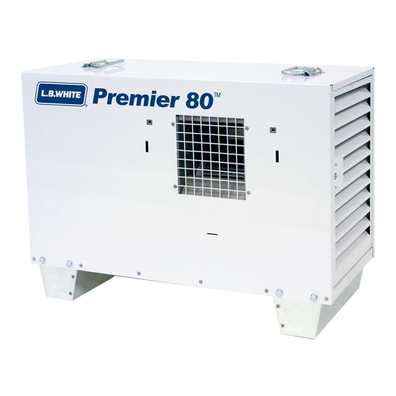
Premier Ductable Heaters
View this manual online at www.lbwhite.com
MODELS
INPUT (Btuh/kW)
TS080
80,000/23.4
TS170
170,000/49.8
CSA 2.14 and is listed and approved
l
FUEL
Propane Vapor
Withdrawal
or
Natural Gas
Certification by:
150-30033 REV.A
Advertisement
Table of Contents

Related Manuals for L.B. White TS080


Summary of Contents for L.B. White TS080
- Page 1 *Requires an app like QR Droid for Android or QR Reader for iPhone. We, at L.B. White, thank you for your confidence in our products and welcome any suggestions or comments you may have...contact us at 1-800-345-7200, or email us at customerservice@lbwhite.com.
- Page 3 Save this Owner’s Manual for future use and reference. ■ Owner’s Manuals and replacement labels are available at no charge. See website, or for assistance, contact L.B. White at 1-800-345-7200. WARNING ■ Proper gas supply pressure must be provided to the inlet of the heater.
-
Page 4: Table Of Contents
Electrical Connection and Ladder Diagram, TS080/170 ........ -
Page 5: Heater Specifications
Heater Specifications Model TS080 TS170 SPECIFICATIONS Propane Natural Propane Natural Fuel Type Maximum Input (Btuh/kW) 80,000/23.4 170,000/49.8 Burner Manifold Pressure 4.0/1.0 10.0/2.49 4.0/1.0 (Inches W.C./kPa) 10.0/2.49 nlet Gas Supply Pressure Acceptable MAX. 13.5/3.36 at the Inlet of the Heater for Purpose of Input Adjustment (Inches MIN. -
Page 6: Safety Precautions
Safety Precautions WARNING Asphyxiation Hazard ■ Do not use this heater for heating human living ■ Improper combustion can lead to carbon monoxide quarters, garages, workshops, or other such confined poisoning leading to serious injury or death. Symptoms spaces. of carbon monoxide poisoning can include headaches, dizziness and difficulty in breathing. - Page 7 Commonwealth of Massachusetts. 11. Always turn off the gas supply to the heater if the heater 2. All installations and applications of L.B. White heaters is not going to be used in the heating of the work space. must meet all relevant local, state and national codes.
-
Page 8: Installation Instructions
End Diffuser Part Number: 26350 DO NOT USE ANY OTHER DUCTWORK, DUCTING,FIELD 1. Read all safety precautions and follow L.B. White FABRICATED DUCTS, TARPS,STOVE PIPE, or any other recommendations when installing this heater. If... -
Page 9: Propane Gas Supply Sizing
Do not use the heater in an propane gas liquid withdrawal system or application. -- Stand clear while the main burner ignites to If you are in doubt, contact the L.B. White Co., Inc. prevent injury caused from hidden leaks that could cause flashback. -
Page 10: Sliding Handle Assembly (Premier 170)
SLIDING HANDLE Premier 170 The Premier 170 is equipped with sliding handles for FIG. 1 EXTEND HANDLE convenient “wheel-barrow” style mobility. UNTIL IT SNAPS INTO RETAINING HOLE -- Depress the snap-button on the underside of the sliding handle storage bracket. -- Fully extend both handles until the snap button locks HANDLE BRACKET into place. -
Page 11: Wheel, Leg & Lifting Handle Assembly (Premier 170)
WHEEL, LEG & LIFTING HANDLE ASSEMBLY Premier 170 See Fig. 4 for assembly of components. Ensure all hardware is tightened securely. FIG. 4 REMOVE CASE SCREW AT EACH END OF HEATER (BOTH SIDES) BEFORE INSTALLING U-HANDLES. HANDLE - U, WITH 8" LEGS WASHER 5/16 (QUANTITY 8) BOLTS 5/16-18 X 1"... -
Page 12: Hose And Regulator Assembly
HOSE AND REGULATOR ASSEMBLY 1. Connect rigid end of hose to regulator outlet. Connect 2. The hose may be coiled up and hung on the hose other end to hose adapter at heater. Tighten securely. hanger as shown in Fig. 7. See Fig 6. -
Page 13: Duct Kit Assembly
DUCT KIT ASSEMBLY Accessory 26346 1. Extend duct kit to 12 ft./3.65 m. length. FIG. 9 2. See Fig. 9 for installation of duct. Hand tighten the screws snugly. (Note: Slots are also provided at the sides of heater’s air discharge to accomodate earlier style duct adapters with tab mounting configuration.) 3. -
Page 14: End Diffuser Assembly
INTO SLOT BEFORE TIGHTENING WING SCREWS INTO CAGE NUTS. CONNECTING REGULATOR TO GAS SUPPLY TS170G-07 FIG. 13 ■ Only use the L.B. White regulator supplied with the heater. ■ The heater must be regulated at all times for proper operation. ■... -
Page 15: Start-Up Instructions
Start-Up Instructions 1. Connect the electrical cord to an approved electrical FIG. 15 outlet. A selector switch located on the back of the heater allows heater operation in either heating or ventilation (no heat) modes. See Fig. 15. A. Heat Mode Operation a. -
Page 16: Shut-Down Instructions
L.B. White Co., Inc. Dataplates, start- up and shut-down instructions and warnings are 4. Regulators can wear out and function improperly. -
Page 17: General
GENERAL 3. The high limit switches, HEAT/VENT switch, and WARNING thermostat can be tested by disconnecting the leads Burn Hazard at the component, and jumpering the leads together: ■ Heater surfaces are hot for a period of time after the heater has been shut down. -
Page 18: Air Proving Switch
AIR PROVING SWITCH 1. Open louvered case access panel. FIG. 17 NUTS 2. Remove two sheet metal screws holding air proving PADDLE switch blower housing. Remove assembly by turning switch assembly 90 degrees so the switch paddle can be pulled through oblong hole on side of fan housing. See Fig. -
Page 19: Testing The Manual Reset High Limit Switches
For Premier 170 heaters, the bolt is accessible through an opening in the heater’s support leg. Use a ratchet with extension and 9/16 SPACER in. socket. See Fig. 22. For model TS080, also remove the spacer between heater base and burner. See Fig. 23. - Page 20 4. Pivot the gas control assembly to expose the burner FIG. 25 orifice. See Fig. 24. Replace components as needed. Premier 80 FIG. 24 ORIFICE HOLDER ORIFICE GAS CONTROL 8° CONTROL VALVE Premier 170 5. When assembling the control valve to manifold, the CONTROL valve must be offset 8 degrees from the orifice holder ORIFICE...
-
Page 21: Gas Pressure Checks
GAS PRESSURE CHECKS 2. Securely connect a pressure gauge to each pressure WARNING tap. ■ Do not disassemble the gas control valve. 3. Open the fuel supply valves to the heater and ■ reconnect the heater electrical supply. Do not attempt to replace any components of the gas control valve. -
Page 22: Troubleshooting Information
Troubleshooting Information READ THIS ENTIRE SECTION BEFORE BEGINNING Ventilation Mode Problem Page TO TROUBLESHOOT PROBLEMS. Motor Does Not Run ......26 Components should be replaced only after each step has WARNING been completed and replacement is suggested in the flow... -
Page 28: Electrical Connection And Ladder Diagram, Ts080/170
Electrical Connection and Ladder Diagram PREMIER 80/170 Black/Noir/Negro Blue/Bleu/Azul Brown/Bruin/Marròn HEAT/ 115 VAC CHALEUR/ Green/Vert/Verde INICIO Gray/Gris Red/Rouge/Rojo MOTOR IND OFF/ FERME/ White/Blanc/Blanco APAGADO Yellow/Jaune/Amarillo VALVE MV VENT/ AIRPROVE PS2 VENTILACIÒN AIRPROVE PS1 APS: Air Proving Switch/Interrupteur de Vérification de Débit d'Air/Interruptor de TRANSFORMER W Comprobaciòn de Aire DSI:... -
Page 29: Heater Component Function
Heater Component Function Air Proving Switch High Limit Switch Safety device used to insure that the proper air flow is being Safety device wired into the control system which is used to achieved before the gas valve is opened. break an electrical circuit to the gas control valve in event of overheat situation. -
Page 30: Parts Identification
Parts Identification PREMIER 80 PARTS SCHEMATIC... -
Page 31: Premier 80
PREMIER 80 PARTS LIST Item Description Part Number Regulator Propane Gas 26377 Natural Gas 21999 Handwheel w/ Spring Propane Gas 26395 Universal Hose Kit, 4.57 m. Hose w/ Adapters 24600 Adapter 1/2 NPT x 5/8 - 18 06655 09309 Screw 09425 Valve, Gas Control Propane Gas... - Page 32 PREMIER 170 PART SCHEMATIC...
-
Page 33: Premier 170
PREMIER 170 PARTS LIST Item Description Part Number Regulator Propane Gas 26419 Natural Gas 09795 Hand Wheel with Spring Propane Gas 26395 Universal Hose Kit, 4.57m. Hose w/ Adapters 24600 Wheel Kit 26418 Axle 26415 Cotter Pin 26417 Kit, Leg Bracket 26413 Bolt and Washer 25866... -
Page 34: Warranty Policy
Replacement Parts and Service Contact your local L.B. White dealer for replacement parts Be sure that you have your heater model number and and service. You may also call the L.B. White Co., Inc. at 1-800- configuration number when calling. 345-7200,...
Need help?
Do you have a question about the TS080 and is the answer not in the manual?
Questions and answers