
Related Manuals for IWILL DX400-SN


Summary of Contents for IWILL DX400-SN
- Page 1 IWILL DX400-SN (Version 1.2A) High-End Workstation Motherboard User's Manual FB11360030000 - 1 -...
-
Page 2: Table Of Contents
Contents Motherboard Description 1. Overview… … … … … … … … … … … … … … … … … … … … … … … … … … … ..… … … … 4 Feature Summary Manufacturing Options Motherboard Layout…... - Page 3 Fan Connectors AOL2 Technology Wake on Lan Technology Wake on Ring Technology Wake on USB 9. LAN subsystem… … … … … … … … … … … … … … … … … … … … … … … … … … … ..30 Intel 82550 Lan Controller Alert On LAN Component LAN subsystem software...
-
Page 4: Motherboard Description 1.Overview
Motherboard Description 1.Overview This section provides a summary of the DX400-SN motherboard’s features and the manufacturing options available. Feature Summary This table summarizes the DX400-SN motherboard’s major features. Item Description Remark Supports Dual Intel Xeon (socket 603) processor Supports CPU speed from 1.3 GHz up to 2GHz and higher... - Page 5 ATX form-factor with 305mm x330mm board size Specifications - Optional Components The following on-board components are optional at the time of purchase: Please contact with IWILL to determine which options are available to you. Options Audio Audio Codec’97 (AD1881A) compatible using an AD1881...
-
Page 6: Motherboard Layout
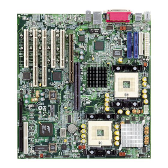
2 Motherboard Layout The picture shows the location of the major components on the motherboard. CPU 1 Fan Connector Internal Speaker Primary IDE Connector Qlogic 12160 SCSI Controller Secondary IDE Connector SCSI controller ROM Diskette Drive Connector Front 90x90mm System Fan Connector WTX Power Connector A Front Panel Connector Rear 120x120mm Case Fan Connector... -
Page 7: Supported Processors
Supported Processors This section describes the processors supported by the DX400-SN motherboard and how to install them. The DX400-SN Motherboard only supports Intel Pentium Xeon processors with a Front Side bus speed of 400 MHz . If two processors are installed, both processors must run the same core frequency speed. - Page 8 Clip Socket Heatsink Processor Screw Screw Chassis Retainer Nuts - 8 -...
- Page 9 Processor installation. a. Be sure the first pin position in the right direction and install the processor(C), see figure down below. b. There is a handle at the side of socket603 (F), and it should be fully pulled up or the processor(C) can not be installed on it.
- Page 10 Push the both ends of clip (A) once at a time with the fastener retainer (E). There are three major steps about the Pentium Xeon processor installation for a DX400-SN motherboard. 1. Motherboard and retainers installation.
- Page 11 Please follow the following steps to fix the retainer (E) on the motherboard (G). Screws: a. Support the motherboard (G) on the chassis (I) after nuts (J) and screws (H) have screwed on the chassis (I) first, see the figure3. b.
-
Page 12: System Memory
A Memory Expansion Card may be used to increase memory size configurations, which are required for most server and workstation designs. The Intel 860 chipsets provide memory repeater hubs that allow for this memory expandability. IWILL MEC card allows for memory support of up to 4GB. ECC Memory ECC memory detects multiple-bit errors and corrects single-bit errors. - Page 13 b. If there is any CRIMM module will be installed, it is recommended that the CRIMM module should be installed near the terminators, see the figure down below. c. The minimum memory installation we suggested is four exactly the same modules with four CRIMM modules.
- Page 14 Supported RIMM Sizes RIMM Size RIMM Technology 64 MB 64 M bit 128 MB 128 M bit 256 MB 256 M bit 512 MB 256 M bit MEC8 Usage The MEC8 (using two memory repeater hubs) supports the following memory features: * Up to eight 2.5V, 184-pin RDRAM* interface memory modules (RIMMs*) * 300/400MHz Direct RDRAM* interface * Support for PC600 PC800 RDRAM*...
- Page 15 MEC8 Card Specification MEC8 SPEC. Comments Dimensions W x D in mm 325X140 Contain the golden finger Number of RDRAM sockets Voltage 2.5 & 1.8V Max Memory 256Mbit technology x 16 devices You must first populate J8 and J4.and J7 and J3. Installing RIMMs Channel B2 Channel A2...
- Page 16 RIMM Installation Combinations Combination 1 CRIMM CRIMM RDRAM RDRAM CRIMM CRIMM RDRAM RDRAM Combination 2 RDRAM RDRAM RDRAM RDRAM RDRAM RDRAM RDRAM RDRAM CRIMMs must be installed in unpopulated RIMM connectors for the motherboard to boot. RIMMs must be installed as described in above table or the motherboard will not boot. The memory must be the same size, density, type, and speed.
-
Page 17: Intel 860Chipset
The new specification is primarily designed to deliver additional electrical power to the graphics add-in cards. The AGP Pro universal connector on the DX400-SN motherboard is designed to deliver up to 50 Watts of electrical power. The DX400-SN is designed to support AGP 1.5V add-on cards only! Do Not Use 3.3V add-on cards. - Page 18 Universal Serial Bus The motherboard has four Universal Serial Bus (USB) ports and two USB headers; one USB peripheral can be connected to each port. For more than two USB devices, an external hub can be connected to either port. The four USB ports are implemented with stacked back panel connectors.
-
Page 19: Ide Support
* Support for isochroous and asynchronous transfer types over the same set of wires * Support for up to 127 physical devices * Guaranteed bandwidth and low latencies appropriate for telephony, audio and other applications * Error-handling and fault-recovery mechanisms built into the protocol The USB controller provides enhanced support for the Universal Host Controller Interface (UHCI). - Page 20 The BIOS supports logical block addressing (LBA) and extended cylinder head sector (ECHS) translation modes. The drive reports the transfer rate and translation mode to the BIOS. The motherboard supports laser servo (LS-120) diskette technology through its IDE interfaces. The LS-120 drive can be configured as a boot drive. The motherboard allows connection of an LS-120 compatible drive and a standard 3.5-inch diskette drive..
-
Page 21: I/O Controller
5. I/O Controlle The Winbond* W83627HF I/O Controller provides a low pin count (LPC) interface and 3.3V Operation with the following features: * Two serial port * One parallel port with Extended Capabilities Port (ECP) and Enhanced Parallel Port (EPP) support * Serial IRQ interface compatible with serialized IRQ support for PCI systems (16C550 compatible ) * PS/2-style mouse and keyboard interfaces... -
Page 22: Parallel Port
Parallel Port The connector for the multi-mode, bi-directional parallel port is a 25-pin D-sub connector located on the back panel. In the BIOS Configuration Manager program, the parallel port can be configured for the following: * Output only (PC AT*-compatible mode) * Bi-directional (PS/2 compatible) * Extended Parallel Port (EPP) * Enhanced Capabilities Port (ECP) -
Page 23: Audio Subsystem
6. Audio Subsystem (Optional) This section provides an overview of the DX400-SN audio subsystem. It describes the features of the AD1881 Analog Devices* Audio Codec and the various connectors included in the audio Sub system. Analog Device* AC ‘ 97(AD1881) Audio Codec The board has one AD1881A V 2.0-compliant audio feature, an Analog Devices* AD1881 Analog... -
Page 24: Audio Connectors
Audio Connectors The audio connectors include the following: * ATAPI-style CD-IN * ATAPI-style Telephony * Back panel audio connectors - Line in - Line out - Mic in Line In Line Out ATAPI-style CD-IN connector A 1x4-pin, connector interfaces an internal CD-ROM drive with the audio mixer. ATAPI-style AUX-IN connector A 1x4-pin ATAPI-style connector connects the mono-aural audio signals of AUX-IN device to the audio subsystem. -
Page 25: Hardware Management Features
7. Hardware Management Features The hardware management features enable the board to be compatible with the Wired for Management ( WfM ) specification. The board has several hardware management features, Including the following: * Hardware monitor subsystem * Chassis intrusion detection connectors * Fan control and monitoring Hardware Monitor Subsystem The hardware monitor subsystem provides low-cost instrumentation capabilities. - Page 26 This threshold temperature can be set in the Configuration Manager. The user can set the threshold to 40°C for continuous operation of the system fans in high-speed mode in the S0 and S1 sleep states. Controlling System Fan Speed 1. Set the Auto Fan Startup Temperature as minimum degree. 2.
-
Page 27: Power Management Features
8. Power Management Features Power management is implemented at several levels including: * Software support of Advanced Configuration and Power Interface (ACPI) * Hardware support: - Power connectors - Fan connectors - Alert on LAN* 2 Technology - Wake on LAN* Technology - Wake on Ring Technology - Wake on USB mouse/keyboard - Wake on Real Time Clock... - Page 28 Fan Connector Descriptions Connector Function System Fan C, F, G Provides +12 VDC for a system or chassis fan Support speed control A tachometer feedback connection is also provided. Processor Fan A , B , D , E Provides +12 VDC for a system or chassis fan The processor fan is always on.
-
Page 29: Wake On Lan Technology
Wake on LAN Technology Wake on LAN Technology enables remote wakeup of the computer through a network. The LAN subsystem monitors network traffic at the Media Independent Interface. Upon detecting a Magic Packet * frame, the LAN subsystem asserts a wakeup signal that powers up the computer. The motherboard supports Wake on LAN through the PCI bus PME# signal and the Intel 82550 LAN controller. -
Page 30: Lan Subsystem
9 LAN Subsystem (optional) The Intel 82550 10/100 Mbps Fast Ethernet, Wired for Management (WfM) support, LAN subsystem provides both 10Base-T and 100Base-TX connectivity. Features include * Full Duplex support at both10Base-T and 100Base-TX capability using a single RJ-45 connector * 32-bit, 33MHz direct bus mastering on the PCI bus * IEEE 802.3u Auto-Negotiation support Intel 82550 LAN Controller (optional) -
Page 31: Lan Connector Leds
RJ-45 LAN Connector (Optional) LEDs Two LEDs are built into the RJ-45 LAN connector. The table describes the LED states when the board is powered up and the LAN subsystem is operating. LAN Connector LED States LED Color LED State Condition Green Off 10 M bit/sec... -
Page 32: Jumper Setting & Connector
10 Jumper Setting & Connector Back Panel Connectors PS2/ Mouse USB Port 3 USB Port 1 USB Port 4 Parallel Port Serial Port 2 Serial Port 1 Line In USB Port 2 Line Out PS2/ Keyboard Mic In - 32 -... -
Page 33: Fan Connectors
Fan connectors Fan Connectors 1. System Fan with speed control ( C , F , G ) Signal Ground (Fan Enable) +12V Tachometer (out) 2. Processor Fan not support speed control ( A , B , D , E) Signal Ground (Fan Enable) +12V - 33 -... -
Page 34: Peripheral Connector
Peripheral Connector Primary IDE SCSI CHA_68PIN Secondary IDE CD-IN Diskette AUX_IN SCSI CHB_50PIN Chassis SCSI CHB_ 68PIN - 34 -... -
Page 35: Front Panel Connectors
Front Panel Connectors Power Switch Power/ACPI LED Hard Disk Activity LED SCSI Activity LED Input Signal Signal - 35 -... - Page 36 For CMOS clear jumper Case For case-open pin header 1-2 : normal 2-3 : CMOS clear CONFIGURE JUMPER USB Header For on-board USB pin header 1-2 : NORMAL 2-3 : CPU speed in safe mode OFF:RECOVERY JP16 For FWH protection function IR Connector For IR pin header 1-2 : soft protect...
-
Page 37: Thermal Sensor
Thermal Sensor Connector Specifications Specification Description Revision Level Audio Codec’97 Revision 2.1, May 1998 AC ‘97 (AD1881A) Intel Corporation The specification is available at: ftp://download.intel.com/pc-supp/platform/ac97 ACPI Advance Configuration Revision 1.0, July 1, 1998 and Power Interface Intel Corporation, Microsoft Corporation*, and Specification Toshiba Corporation*. - Page 38 ATAPI ATA Packet Interface for X3T10/2008D Revision 6 CD-ROMS The specification is available at: http://www.t13.org ATX Specification Revision 2.01, February 1997 Intel Corporation The specification is available at: http://developer.intel.com/design/motherbd/atx.htm Enhanced Parallel Port IEEE 1284.1 standard, Mode [1 or 2], v1.7 IEEE The specification is available at: http://standards.ieee.org/...
- Page 39 Corporation*, IBM Corporation*, Intel Corporation, Microsoft Corporation*, NEC*, and Northern Telecom* The specification is available at: http://www.usb.org/developers Wired for Management Version 2.0, December 18, 1998, Baseline Intel Corporation The specification is available at: http://developer.intel.com/ial/WfM/wfmspecs.htm Workstation Chassis Version 1.1, February 1999 Specification Intel Corporation The specification is available at:...
- Page 40 Mic In Connector Signal Name Sleeve Ground Mono In Ring Electret Bias Voltage CD-ROM Header (J3A1) Signal Left CD In Ground Ground Right CD In AUX-IN Style Header (J2B1) Signal Left Channel Ground Right Channel Diskette Drive Connector (J3G2) Signal Name Signal Name Ground DENSEL...
- Page 41 Front Panel Connector (J1H1) Signal Name Signal Name PWR_ BTN 5VSB 5VSB SUS_LED Keylock HD_LED - 41 -...
-
Page 42: Bios Setup
11. BIOS Setup BIOS Introduction Using BIOS setup program Move to the previous field Down Move to the next field Left Move to the field on the left hand side Right Move to the field on the right hand side <Esc>... -
Page 43: Standard Cmos Features
Standard CMOS Features Date This field specifies the current date. The date format is <month>, <day>, and <year>. Time This field specifies the current time. The time format is <hour>, <minute>, and <second>. The time is calculated based on the 24-hour (military-time) clock. IDE Primary Master / Primary Slave / Secondary Master / Secondary Slave Press “Enter”... - Page 44 Advanced Boot Option First / Secondary / Third Boot Device The BIOS attempts load the operating system from the device in the sequence selected in these items. LAN Boot Device Disable (Default Setting) When enabled, the system will boot from LAN. Quick Power On Self Test This field allows the system to skip certain tests while booting.
- Page 45 Boot Up Floppy Seek Seeks disk drives during boot up. Disabling speeds boot up. Boot Up Num Lock Status This field determines the configuration of the numeric keypad after system boot up. If open the keypad uses numbers keys. If close the keypad uses arrow keys. Power-on Function This field configures the Power-on mode of the system.
-
Page 46: Advanced Chipset Features
Advanced Chipset Features This setup page is used to specify advanced features available through the chipset. The default settings have been chosen carefully for most operating conditions. DO NOT change the value of any field in this setup page without full understanding. CPU L1 &... -
Page 47: Integrated Peripherals
RDRAM Bus Frequency This function sets frequency of RDRAM memory. [Default is Auto ] DRAM Data Integrity Mode [Default is ECC ] Memory Hole At 15M-16M This function allows you to reserve an address space for others device that require it. [Default is Disabled ] Delayed Transaction When enabled, the south bridge ICH2 will supports the Delayed Transaction mechanism when it is the target... - Page 48 IDE Primary Master / Slave UDMA IDE Secondary Master / Slave UDMA If you select Auto, the IDE controller uses Ultra DMA 33/66/100 Mode to access Ultra DMA-capable IDE devices. Depend on the resent of negotiation with your HDD. The maximum transfer rate of Ultra DMA 100 Mode is 100 MB/sec.
-
Page 49: Power Management Setup
3F8/IRQ4 (Default Value) Port address 3F8h, IRQ4 2F8/IRQ3 Port address 2F8h, IRQ3 3E8/IRQ4 Port address 3E8H, IRQ4 2E8/IRQ3 Port address 2E8h, IRQ3 Auto BIOS assigns port address and IRQ channel automatically. Disabled Disables serial port Onboard Parallel Port This field configures the onboard parallel port. There are several port addresses and IRQ channels to select from. - Page 50 Power Management This feature allows the user to select the default parameters for the power-saving mode. Min saving When idle for one hour, the system enter suspend mode Max Saving When idle for fifteen minutes, the system enters suspend mode. User Define (Default Value) User can specify the time the system enter suspend mode.
- Page 51 Power On/Resume by Alarm When enabled, you can set the date and time to automatically power-on your PC (similar to an alarm clock). Enabled Sets Date (0-31) and Timer (hr, min, sec) to power-on the PC. When date is set to 0, the Timer is set for every day.
-
Page 52: Pnp/Pci Configurations
PnP/ PCI Configurations PNP OS Installed The field specifies whether a Plug and Play operating system is installed. Yes, No (Default Value) Reset Configuration Data Normally, you leave this field Disabled. Select Enabled to reset Extended System Configuration Data (ESCD) when you exit Setup if you have installed a new add-on and the system reconfiguration has caused such a serious conflict that the operating system can‘t boot. -
Page 53: Security Features
DMA Resources This sub menu can let you control the memory resource. Reserved Memory Base Reserved a low memory for the legacy device (non-PnP device). [C800, CC00, D000, D800, DC400, N/A (Default Value)] Reserved Memory Length Reserved a low memory length for the legacy device (non-PnP device). [8K (Default Value), 16K, 32K, 64K] Security Features Set Supervisor / User Password Setting... -
Page 54: Cpu Smart Setting
To disable a password, bring the cursor to this field, then press <Enter>. The computer will display the message, ”Enter Password ”. Press <Enter>. A message will confirm that the password is disabled. Once the password is disabled, the system will boot and you can enter setup program freely. CPU Smart Setting CPU smart setting provides users a fuss free CPU frequency set up procedure. -
Page 55: Pc Health Status
PC Health Status This page is monitoring your status of computer. On the screen display CPU/System temperature, FAN speed, and voltages. Load Fail-Safe Defaults When you press <Enter> on this item. You get a confirmation dialog box with a message similar to: Press “Y”... - Page 56 Load Optimized Defaults When you press <Enter> on this item. You get a confirmation dialog box with a message similar to: Press “Y” loads the default values that are factory settings for optimal performance system operations. Save & Exit Setup When you press <Enter>...
- Page 57 Exit Without Saving When you press <Enter> on this item. You get a confirmation dialog box with a message similar to: Press “Y” leaves current CMOS value and exit BIOS setup program Do not save changes and exit setup - 57 -...
-
Page 58: Fast!Util (On-Board Scsi Bios Utility)
12 Fast!UTIL (On-Board SCSI BIOS Utility) Introduction The on-board SCSI can be configured using Fast ! UTIL. Access Fast ! UTIL by pressing <ALT>-<Q> during the on-board BIOS initialization (it may take a few seconds for the Fast ! UTIL menu to appear). CAUTION! If the configuration settings are incorrect, your on-board SCSI will not function properly. - Page 59 Host Adapter Settings From the Configuration Settings menu in Fast ! UTIL, select Host Adapter Settings. The default settings for the on-board SCSI host are listed in table A-1 and described in the following paragraphs Table A-1. Host Adapter Settings Setting Options Default...
- Page 60 The on-board SCSI is designed to sense and configure the devices connected to your motherboard. With he Adapter Configuration set to Manual, the Auto-configure option gives you control of when the bus is scanned and configured. Selecting the Auto-configure SCSI Devices option from the Configuration Settings menu causes the on-board SCSI to scan the devices on the SCSI bus and set the following options, based on the capabilities of each device: Enable Device...
-
Page 61: Scan Scsi Bus
Scan SCSI Bus This option scans the SCSI bus and lists all the connected devices by SCSI ID. Information about each device is listed, for example, vendor name, product name, and revision. This information is useful when configuring your On-board SCSI and attached devices. SCSI Disk Utility This option scans the SCSI bus and lists all the connected devices by SCSI ID. -
Page 62: Appendix
13 Appendix Beep Codes Currently there are two kinds of beep codes in BIOS. This code indicates that a video error has occurred and the BIOS cannot initialize the video screen to display any additional information. This beep code consists of a single long beep followed by three short beeps. The other code indicates that your DRAM error has occurred. -
Page 63: Award Bios Post Control Flow
AWARD BIOS POST CONTROL FLOW POST (hex) Description Test CMOS R/W functionality. Early chipset initialization: -Disable shadow RAM -Disable L2 cache (socket 7 or below) -Program basic chipset registers Detect memory - Auto-detection of DRAM size, type and ECC. Auto-detection of L2 cache (socket 7 or below) Expand compressed BIOS code to DRAM Call chipset hook to copy BIOS back to E000 &... - Page 64 Reserved Detect CPU information including brand, SMI type (Cyrix or Intel) and (CPU level (586 or 686). Reserved Reserved Initial interrupts vector table. If no special specified, all H/W Interrupts are directed to SPURIOUS_INT_HDLR & S/W Interrupts to SPURIOUS_soft_HDLR. Reserved Initial EARLY_PM_INIT switch.
- Page 65 Reserved Invoke Video BIOS Reserved 1. Initialize double-byte language font (Optional) 2. Put information on screen display, including Award title, CPU type, CPU speed , full screen logo Reserved Reserved Reserved Reserved Reserved Reset keyboard if Early_Reset_KB is defined e.g. Winbond 977 series Super I/O chips.
- Page 66 Reserved Initialize USB Keyboard & Mouse Reserved Test all memory (clear all extended memory to 0) Clear password according to H/W jumper (Optional) Reserved Display number of processors (multi-processor platform) Reserved 1. Display PnP logo 2. Early ISA PnP initialization -Assign CSN to every ISA PnP device.
- Page 67 (Optional Feature) Enter AWDFLASH.EXE if : -AWDFLASH is found in floppy drive. -ALT+F2 is pressed Detect serial ports & parallel ports. Reserved Reserved Detect & install co-processor Reserved Init HDD write protect Reserved Reserved Switch back to text mode if full screen logo is supported. - If errors occur, report errors &...
- Page 68 Reserved Reserved Read HDD boot sector information for Trend Anti-Virus code 1. Enable L2 cache 2. Program Daylight Saving 3. Program boot up speed 4. Chipset final initialization. 5. Power management final initialization 6. Clear screen & display summary table 7.
Need help?
Do you have a question about the DX400-SN and is the answer not in the manual?
Questions and answers