Table of Contents
Advertisement
Advertisement
Table of Contents

Related Manuals for VCS VIP 10


Summary of Contents for VCS VIP 10
- Page 1 VIP 10 VIP 1000 User Guide...
- Page 2 Copyright This user guide is the intellectual property of VCS and is protected by copyright. All rights reserved. No part of this document may be reproduced or transmitted for any purpose, by whatever means, electronic or mechanical, without the express written permission of VCS.
-
Page 3: Table Of Contents
Overview of functions ....... . . 12 VIP 10 and VIP 1000 Receiver Connections ....15 VIP 1000 Transmitter Connections . - Page 4 Software update ........79 VIP 10/1000...
- Page 5 Glossary......... . . 105 VIP 10 Specifications....... . . 108 VIP 1000 Specifications.
- Page 6 VIP 10/1000...
-
Page 7: About This User Guide
About this user guide This user guide is intended for persons responsible for the installation and operation of the VIP 10 or the VIP 1000 network video servers. International, national and any regional regulations regarding electrical systems must be adhered to at all times. The user manual describes the installation and operation of the unit. -
Page 8: Intended Use
Chapter 1 Intended use The VIP 10 and VIP 1000 network video servers transmit video, audio and control signals over data networks (such as Ethernet LANs and the Internet). They are designed for use in CCTV systems. By incorporating external alarm devices, various functions can be triggered automatically. -
Page 9: Electrical Shock Hazard
– if foreign matter has infiltrated the unit, – after long storage under adverse conditions or – after exposure to higher than normal stress during transport. In such cases, have the unit checked by VCS. VIP 10 / VIP 1000... -
Page 10: Installation And Operation
Never open the housing of the power supply unit. The power supply unit does not contain parts that you can repair or replace. Ensure that all maintenance or repair work is performed exclusively by qualified personnel (electrical technicians). VIP 10 / VIP 1000... -
Page 11: Supplied Components
Product Description Supplied components Network video server, model VIP 10 or VIP 1000, including plug-in mains adapter RS232 null modem cable Quick start guide “First Steps” in English/German CD with software and user guides System requirements for setup Computer with Microsoft Windows 98/2000/XP operating system and network access and Microsoft Internet Explorer (version 5.5 or higher) or... -
Page 12: Operational Requirements
Receiver VIP or VideoJet units from VCS can be used as receivers. Computers with decoding software such as VIDOS from VCS or Microsoft Internet Explorer can also be used as receivers. - Page 13 Chapter 3 Product Description Video encoding The VIP 10 works with the MPEG-4 video compression standard. The VIP 1000 works with the MPEG-2 and MPEG-4 standards. Due to the efficiency of encoding using MPEG-2, the data rate remains low even with high image quality and can also be adapted to local conditions within wide limits.
- Page 14 Relay output for switching external devices (such as lights or audible alarms) Event-driven, automatic connection (for example when switching on and when alarms are activated) Fast, convenient configuration using a Web browser Firmware update using flash memory Convenient upload of configuration data VIP 10 / VIP 1000...
-
Page 15: Vip 10 And Vip 1000 Receiver Connections
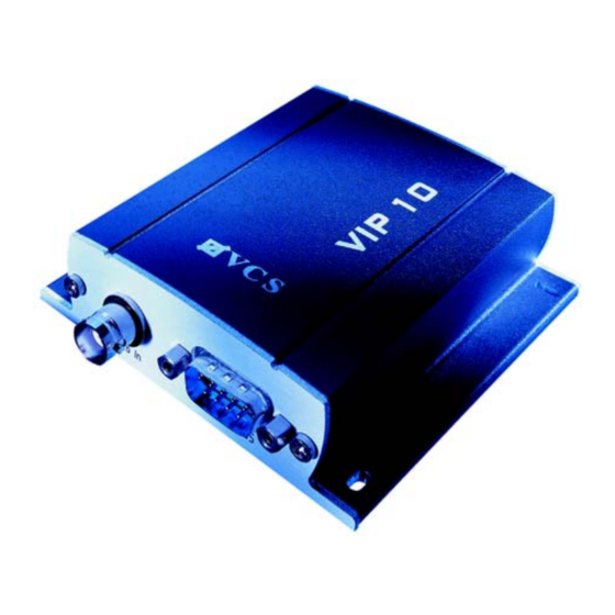
Chapter 3 Product Description VIP 10 and VIP 1000 Receiver Connections 1 BNC jack: Video In (transmitter) or Video Out (receiver), for connecting a video source or an analog video monitor 2 RS232/485 serial interface 9-pin Sub D socket (male) for transmitting control data and... -
Page 16: Vip 1000 Transmitter Connections
7 Network connection LED green, lights up when the device is connected to the network 8 Data transfer LED flashes yellow when data is transmitted over the network 9 RJ45 jack for Ethernet for connecting to the network VIP 10 / VIP 1000... -
Page 17: Installing The Unit
Use only the cables supplied for connections or appropriate cables, which are also shielded against electromagnetic interference. Position and run all cables so that they are protected from damage, and provide strain relief where needed. VIP 10 / VIP 1000... -
Page 18: Connections
You can connect the VIP directly to a 10/100 Base-T network or via a hub. Use a standard UTP Category 5 cable with RJ45 connectors for this. – Connect the unit to the network using the Ethernet jack. VIP 10 / VIP 1000... - Page 19 – Connect a loudspeaker to the appropriate terminals on the orange terminal block of the receiver and check that the connection is secure. VIP 10 / VIP 1000...
-
Page 20: Switching On/Off
"operating status" LED stops flashing red during start-up and becomes yellow. If the network connection is in order, the yellow "network connection" LED is also lit. The flashing orange "data transmission" LED indicates data traffic on the network. VIP 10 / VIP 1000... -
Page 21: Setup Using Terminal Software
You can call up additional submenus and functions using the on-screen commands. If necessary, turn off the local echo so that entered values are not repeated on the screen display. VIP 10 / VIP 1000... - Page 22 – Enter i. The current IP address will be displayed, and you will be requested to enter a new IP address. – Enter the desired IP address and press Enter. The new IP address will be displayed and becomes effective following a restart. VIP 10 / VIP 1000...
- Page 23 Chapter 4 Installation Additional parameters Using the terminal program, you can check other basic parameters and modify them where necessary. Use the on-screen commands displayed in the various submenus for this purpose. VIP 10 / VIP 1000...
- Page 24 VIP 10 / VIP 1000...
-
Page 25: Establishing The Connection
MPEG decoder installation If no video images are displayed when MPEG-2 or MPEG-4 is selected, it may be necessary to install a current MPEG decoder. This software is on the VCS CD included with the package. – Insert the CD into the CD-ROM drive of the computer. The CD should start automatically. - Page 26 – Enter the IP address of the VIP as the URL. The VIP home page will be shown in the browser. If the unit is a transmitter, the home page will be the Livepage (which shows the live video image). VIP 10 / VIP 1000...
- Page 27 Service user name. – Enter the user name and password in the appropriate fields. – Click OK. If the password is correct, the VIP home page will open. VIP 10 / VIP 1000...
-
Page 28: Choosing The Configuration Mode
– Click the Settings link in the top part of the VIP transmitter Livepage. A new page will open, and the desired configuration mode can be selected using the links at the top of the window. VIP 10 / VIP 1000... -
Page 29: Configuration With The Installation Wizard
– Click the button with the wizard icon in the Installation Wizard field. The first screen for the Installation Wizard will appear. – Click Start to launch the wizard. The next screen for the wizard will appear. VIP 10 / VIP 1000... - Page 30 Note Your screen display may differ slightly from the illustration, depending on whether you are working with a transmitter or a receiver and a VIP 10 or a VIP 1000. However, the configuration procedure with the Installation Wizard is the same for all units.
- Page 31 Finish in the last screen. – Go to the last screen of the Installation Wizard if necessary. – Click Finish to finalize the configuration. All settings will be transmitted to the VIP and become effective forthwith. VIP 10 / VIP 1000...
-
Page 32: Configuration In Expert Mode
Your screen display may differ from the illustration, depending on whether you are working with a transmitter or a receiver and a VIP 10 or a VIP 1000. However, navigation on the configuration pages is the same for all units. - Page 33 Set to save the change. Warning! Save each change with the associated Set button. When Set is clicked, only the changes in the relevant (blue-bordered) field are saved. Changes in any other fields are ignored. VIP 10 / VIP 1000...
- Page 34 VIP 10 / VIP 1000...
-
Page 35: Basics
Unit identification The unit can be assigned a name and an ID to facilitate identification. Both make the task of managing video surveillance systems with VIDOS from VCS or other tools much simpler. Unit name: Enter a name for the unit here. -
Page 36: Password Settings
Service or if the unit is not protected by a password. You can change only one password at a time. In order to change the password for another authorization level, you must reload this configuration page. Password confirmation: Re-enter the new password to prevent typing mistakes. VIP 10 / VIP 1000... -
Page 37: Language Selection
(Europe: DD.MM.YYYY; USA: MM.DD.YYYY; Japan: YYYY/MM/DD). Unit date: Enter the current date here. Since the system time is controlled by the internal clock, it is not necessary to enter the day of week. This is added automatically. VIP 10 / VIP 1000... -
Page 38: Timer Server
It will be shown in the video image if this facility has been configured (see page 39). Moreover, the camera name is used by VIDOS, VCS software for managing video surveillance systems, and makes it easier to identify the camera. -
Page 39: Display Stamping
Choose On if a text message should be overlaid in the event of an alarm. Displayed alarm message: Enter the message to be displayed for an alarm. The field can contain up to 31 characters. VIP 10 / VIP 1000... -
Page 40: Mpeg-2 Encoder Configuration (Vip 1000 Only)
The following values can be selected: 1 corresponds to 2MBPS low delay 2 MBit/s transmission rate with low image refresh delay 2 corresponds to 3.5MBPS low delay 3.5 MBit/s transmission rate with low image refresh delay VIP 10 / VIP 1000... - Page 41 I-frame. Note B-Frames have a large delay and are not suitable for some applications, such as manually controlling a dome camera. Keep this in mind when choosing a GOP structure and length. VIP 10 / VIP 1000...
- Page 42 (Program Stream). Select PRG if audio is to be transmitted together with the video images. Audio signals require an additional bandwidth of about 256 kBit/s. Note Choosing VES results in no encoding of audio data. VIP 10 / VIP 1000...
-
Page 43: Mpeg-4 Encoder Configuration
The benefit of this so-called "dual encoding" is that you can transmit and record simultaneously with different compression settings. The parameters for each can be configured to suit the environment used (network architecture, bandwidth, data structures, etc.). VIP 10 / VIP 1000... - Page 44 704 × 288 pixels low res. (QCIF) for connections with low bandwidth, resolution 176 × 144 pixels for DSL connections with 500 kbit/s ISDN (2B) for ISDN connections via two B channels VIP 10 / VIP 1000...
- Page 45 The lower the available transmission bandwidth, the higher this value should be set in order to maintain high-quality images despite the bandwidth. Video resolution: Select the desired resolution for the MPEG-4 video image. The following options are available: VIP 10 / VIP 1000...
-
Page 46: Video Input Settings
If you use the MPEG-4 format for video data, audio transmission can be activated separately here. In this case, the audio data stream requires an additional bandwidth of about 80 kBit/s. VIP 10 / VIP 1000... -
Page 47: Alarm Sources
The VIP can trigger an alarm if the camera image shows too little contrast, possibly indicating that the lens has been sprayed with paint or covered in some way. Select On to enable this function. VIP 10 / VIP 1000... -
Page 48: Alarm Connections
You can select a number of options determining how the VIP responds to an alarm. For example, the VIP can automatically connect to a predefined IP address (VIP receiver or a PC with receiver software). VIP 10 / VIP 1000... - Page 49 Enter the password for the remote device (if it has one) that is to be contacted in response to an alarm. Live video auto-connect: Select On here if an active connection should be established after each reboot, for example following a connection failure or power failure. VIP 10 / VIP 1000...
-
Page 50: Motion Detector
When the system is used for surveillance of indoor areas, ensure constant lighting during the day and at night. Uniform VIP 10 / VIP 1000... - Page 51 The sensor reacts to variations in the brightness of the video image. The darker the observation area, the greater the value that must be selected here. – Adjust the sensitivity by dragging the scroll thumb to the desired setting. VIP 10 / VIP 1000...
- Page 52 In some situations you may want an alarm triggered only if movement takes place in a particular direction. In such cases, enable motion detection and select the direction of movement required to trigger an alarm. – Select On to enable the motion tracking feature of the video sensor. VIP 10 / VIP 1000...
-
Page 53: Relay Action / Relay Operation
You can choose various events that activate the output automatically. Thus, for example, it is possible to switch on a spotlight in response to a motion alarm and switch it off again when the alarm situation is no longer active. VIP 10 / VIP 1000... - Page 54 A name can be assigned to the relay in this field. The name will be shown on the button under Trigger relay. The Livepage can also be configured to display the name next to the relay icon. VIP 10 / VIP 1000...
-
Page 55: Com1 Serial Data Port / Com1 Interface Settings
Transparent. To operate the VIP with a terminal, choose Terminal. Note After selecting a unit, the remaining parameters in the window are set automatically and should not be altered. Baud rate: Select the value for the data communication rate in Bit/s. VIP 10 / VIP 1000... -
Page 56: Network Settings
Interface mode: Select the desired protocol for the serial interface. Half-duplex mode: Choose the setting appropriate for your application. Network settings The settings on this page are used to integrate the unit into an existing network. VIP 10 / VIP 1000... - Page 57 For some routers and switches it can be necessary to set the Ethernet link to a fixed value. In that case select the appropriate value: 10 MBit/s HD = 10 MBit/s half-duplex 10 MBit/s FD = 10 MBit/s full-duplex VIP 10 / VIP 1000...
- Page 58 URL of the DNS server which then returns the valid Internet IP address for automatic connection set up. The default setting for the DNS server IP address is the IP address of the VCS DNS server videotec.info. The VIP contacts the server automatically when a refresh time is specified in the next parameter.
-
Page 59: Multicast Settings
The audio link is likewise established only with a single receiver. It is also generally maintained by the first receiver connected until that connection is closed. VIP 10 / VIP 1000... - Page 60 The network must support group IP addresses and the Internet Group Management Protocol (IGMP). The address range is from 224.0.1.0 to 238.255.255.255. Multicast video port encoder 1 (VIP 10 only): Enter the port address for the video port of encoder 1. Multicast video port encoder 2 (VIP 10 only): Enter the port address for the video port of encoder 2.
-
Page 61: Version Information
Keep a record of these numbers in case technical assistance is required. Hardware version: The hardware version number of the VIP is displayed. Software version: The software version number of the VIP is displayed. VIP 10 / VIP 1000... -
Page 62: Livepage Configuration
Either GIF or JPEG file formats can be used. The file paths must correspond to the access mode (local paths such as C:\Images\Logo.gif for local files and URLs such as http://www.vcs.com/images/logo.gif for files on the Internet). Please note that access to network files requires that the connection be maintained in order to continue displaying the image. - Page 63 The image can be stored on a local computer, a local network or an Internet address. – If necessary, click Search to find a suitable image on the local network. Video from Encoder on live page (VIP 10 only): Select an encoder for the video image on the Livepage. Panorama (Sony camera only): Selecting this option enables the display of a panoramic image.
-
Page 64: Software Update
– If necessary, click Search to find a suitable folder. Software update Software upload: The VIP is designed so its functions and parameters can be updated with firmware. To do this, you transmit the latest firmware update to the unit via the VIP 10 / VIP 1000... - Page 65 This allows a VIP unit to be serviced and updated remotely without intervention by a technician to make on-site changes to the unit installation. The latest firmware can be obtained from VCS Customer Service or downloaded from the Internet at our Web site www.vcs.com.
-
Page 66: Function Test
Check for the following (among other things): the VIP can be contacted remotely, the VIP transmits all the required data, the VIP responds as configured to alarm events and that any peripheral devices respond properly to control signals. VIP 10 / VIP 1000... -
Page 67: Basics
Unit identification The unit can be assigned a name and an ID to facilitate identification. Both make the task of managing video surveillance systems with VIDOS von VCS or other tools much simpler. Unit name: Enter a name for the unit here. -
Page 68: Unit Password
In order to change the password of another authorization level, you must reload this configuration page. Password confirm: Re-enter the new password to prevent typing mistakes. Language selection If more convenient, a different operating interface language can be selected. VIP 10 / VIP 1000... -
Page 69: Date And Time
This is added automatically. Unit time: Enter the current time here or click the Synchr. PC button to copy the system time of your computer to the VIP. VIP 10 / VIP 1000... -
Page 70: Timer Server
Monitor settings The monitor name is used for easier identification of the monitor. It is used by VIDOS, the VCS software for managing video surveillance systems, and makes the task of identifying the monitor easier. The video standard for the connected monitor can also be selected here. -
Page 71: Audio Configuration
Select On if the alarm is to be activated by the external alarm sensor 1. Furthermore, you can choose whether the alarm is to be activated by an Active high or Active low voltage signal. VIP 10 / VIP 1000... -
Page 72: Alarm Connections
1. This setting can also be used to connect two VIP units via a control switch. In this case, a computer is not needed to establish the connection. VIP 10 / VIP 1000... -
Page 73: Relay Action / Relay Operation
Relay action / Relay operation You can configure the switching behavior of the relay output. Open switch relay mode (normally closed contact) or closed switch relay mode (normally open contact) can be specified here. VIP 10 / VIP 1000... - Page 74 Triggering by the alarm input 1 Remote input 1 Triggering by a relay contact at a remote location (only when a connection is established) Unified picture Triggering caused by a lack of contrast in the picture VIP 10 / VIP 1000...
-
Page 75: Com1 Serial Data Port / Com1 Interface Settings
Transparent. To operate the VIP with a terminal, choose Terminal. Note After selecting an interface function, the remaining parameters in the window are set automatically and should not be altered. Baud rate: Select the value for the data communication rate in Bit/s. VIP 10 / VIP 1000... -
Page 76: Network Settings
Select the desired protocol for the serial interface. Half-duplex mode: Choose the setting that is appropriate for your application. Network settings The settings on this page are used to integrate the unit into an existing network. VIP 10 / VIP 1000... - Page 77 For some routers and switches it can be necessary to set the Ethernet link to a fixed value. In that case select the appropriate value: 10 MBit/s HD = 10 MBit/s half-duplex 10 MBit/s FD = 10 MBit/s full-duplex VIP 10 / VIP 1000...
-
Page 78: Version Information
URL of the DNS server which then returns the valid Internet IP address for automatic connection set up. The default setting for the DNS server IP address is the IP address of the VCS DNS server videotec.info. The VIP contacts the server automatically when a refresh time is specified in the next parameter. -
Page 79: Software Update
This allows a VIP unit to be serviced and updated remotely without intervention by a technician to make on-site changes to the unit installation. The latest firmware can be obtained from VCS Customer Service or downloaded from the Internet at our Web site, www.vcs.com. - Page 80 If the message Configuration upload failed is displayed, the file did not upload correctly. Repeat the upload in this case, if necessary with a different file. VIP 10 / VIP 1000...
-
Page 81: Function Test
Check for the following (among other things): the VIP can be contacted remotely, the VIP transmits all the required data, the VIP responds as configured to alarm events and that any peripheral devices respond properly to control signals. VIP 10 / VIP 1000... - Page 82 Configuring the Receiver Chapter 7 VIP 10 / VIP 1000...
-
Page 83: Operation With Microsoft Internet Explorer
(see page 39). Other information may also be shown next to the video image on the Livepage. The display depends on the settings on the configuration page Livepage configuration (see page 62). VIP 10 / VIP 1000... - Page 84 Chapter 8 Image quality The VIP 10 displays either a live video sequence in MPEG-4 format or individual live video frames in JPEG format. Moreover, with the VIP 1000 you can also call up live video images in MPEG-2 format.
- Page 85 VIP, the controls for the device are displayed next to the video image. – To control a peripheral device click the appropriate operating elements. – Move the pointer over the live video image. Further options for peripheral device control will be displayed. VIP 10 / VIP 1000...
- Page 86 – Select Start scan to update the individual images. Stop scan cancels the update. Note The panorama image is displayed only if Show panorama view is selected on the configuration home page Livepage configuration (see page 62). VIP 10 / VIP 1000...
-
Page 87: Saving Snapshots
– Press the Return key or Enter key. A single frame image will be displayed in a new window. – Right-click the image and select Save Picture As... from the context menu. – Save the snapshot in the desired format, giving it a new name. VIP 10 / VIP 1000... -
Page 88: Recording Video Sequences
– Click the icon once more to stop the recording. Note Use the VCS MPEG viewer to play the recorded video. The latest version of the MPEG viewer is on the accompanying software CD. It is also available from VCS Customer Service or as an Internet download at www.vcs.com. -
Page 89: Operation With Microsoft Internet Explorer
Preview This area displays a snapshot of the video image from the transmitter, which is online at that moment. In addition to the unit name, the snapshot provides other means of identifying the transmitter. VIP 10 / VIP 1000... -
Page 90: Connection Between The Receiver And Transmitter
– Click Connect to begin displaying the video images on the connected monitor. The video image from the selected source can now also be seen under Monitor. Terminating a connection – Click the icon with the red x to stop the video display on the monitor. VIP 10 / VIP 1000... -
Page 91: Hardware Connections Between Vip Units
There are three options for establishing a connection between a VIP transmitter and a VIP receiver in a closed network: when an alarm signal is given, using a terminal program or using a Web browser VIP 10 / VIP 1000... - Page 92 – Select a transmitter from the Available sender units. A JPEG snapshot of the selected video source will be displayed on the page. – Click Connect to begin showing the video images on the monitor. VIP 10 / VIP 1000...
-
Page 93: Closing The Connection
Closing the connection using a Web browser – Use the Web browser to connect to the VIP receiver. Its home page will be displayed. – Click the icon with the red x to stop the video display on the monitor. VIP 10 / VIP 1000... - Page 94 VIP 10 / VIP 1000...
-
Page 95: Operation With Vidos
Microsoft Windows operating systems. Its main function is decoding video, audio and control data from a remote transmitter. There are many options available for operation and configuration when using VIP devices in combination with VIDOS. Refer to the software documentation for more details. VIP 10 / VIP 1000... - Page 96 VIP 10 / VIP 1000...
-
Page 97: Testing The Network Connection
Uploading the wrong files can result in the unit no longer being addressable, requiring it to be replaced. Do not interrupt the firmware installation for any reason! Interruption will damage the Flash EPROM. This VIP 10 / VIP 1000... -
Page 98: Repairs
Ensure that maintenance or repair work is performed only by qualified personnel (electrical technicians), or contact your VCS dealer service center. Transfer and disposal The VIP should only be passed on together with this reference manual. -
Page 99: Troubleshooting
Appendix Troubleshooting If a problem cannot be resolved, please contact VCS Customer Service (support@vcs.com). The version numbers of the internal processors can be viewed on a special page. Please note this information before contacting Customer Service. – In the address field of the browser, append /version.htm to the IP address of the unit (e.g. - Page 100 The unit is no longer Power failure when Replace the unit and have it operational after a uploading the update file. checked by VCS. firmware upload. VIP 10 / VIP 1000...
-
Page 101: Leds
Flashing yellow/red: Upload failed. Network connection LED Lit green: Connected to the network. Not lit: Not connected to the network. Data transfer LED Flashing orange: Data transfer via the network. Not lit: No data transfer. VIP 10 / VIP 1000... -
Page 102: Rs232/485 Interface
RS232 or RS422/485 protocol. The protocol used depends on the current configuration (see page 55). The serial interface on the VIP 10 uses a Sub D connector and the VIP 1000 uses an RJ45 connector. - Page 103 RxD+ (receive data plus) CTS (clear to send) TxD- (transmit data minus) – – – – GND (ground) GND (ground) – – TxD (transmit data) TxD+ (transmit data plus) RTS (ready to send) RxD- (receive data minus) VIP 10 / VIP 1000...
-
Page 104: Connection Jacks
Terminal allocation Terminal Function audio input (line level) audio output (line level) Alarm 1 input alarm output power supply, 9 to 24 V electrical ground electrical ground Alarm 2 input alarm output – power supply VIP 10 / VIP 1000... -
Page 105: Glossary
IP address A 4-byte number uniquely defining each device on the Internet. It is usually written in dotted decimal notation with periods separating the bytes, for example "209.130.2.193". ISDN Integrated Services Digital Network Internet Service Provider VIP 10 / VIP 1000... - Page 106 Server push A continuous flow of data sent from the transmitter to the Web browser Subnet mask See netmask Transfer Control Protocol User Datagram Protocol Uniform Resource Locator Unshielded Twisted Pair See wide area network VIP 10 / VIP 1000...
- Page 107 Chapter 13 Appendix Wide area network A long distance link used to extend or connect remotely located local area networks VIP 10 / VIP 1000...
-
Page 108: Vip 10 Specifications
1 × USB 2.0 Alarm input 2 × push-in terminal, max. 24 V, activation resistance 10 Ohm Relay output 1 × push-in terminal, 30 V , 1 A Indicators 3 LEDs (operating status, network connection, data transfer) VIP 10 / VIP 1000... - Page 109 EN 55103-1, -2; EN 55130-4; EN 55022; EN 55024; EN 61000-3-2; EN 61000-3-3; FCC 47 CFR Ch. 1, Part 15 Dimensions (w × h × d) 65 × 27 × 108 mm Weight approx. 300 g (without power supply) VIP 10 / VIP 1000...
-
Page 110: Vip 1000 Specifications
1 × push-in terminal 3.0 V , 50 kOhm, mono Audio output 1 × push-in terminal 2.5 V , 60 mW, min. 8 Ohm, mono Data interfaces 1 × RS232/RS422/RS485, bidirectional, 9-pin Sub-D 1 × USB 2.0 VIP 10 / VIP 1000... - Page 111 EN 55103-1, -2; EN 55130-4; EN 55022; EN 55024; EN 61000-3-2; EN 61000-3-3; FCC 47 CFR Ch. 1, Part 15 Dimensions (w × h × d) 65 × 27 × 108 mm Weight approx. 300 g (without power supply) VIP 10 / VIP 1000...
- Page 112 Appendix Chapter 13 VIP 10 / VIP 1000...
- Page 113 Data interface 18 Installation 10 Data rate: 45 Installation location 17 Data terminal 21 Installation requirements 17 Date format 37 Installation Wizard 28 Defaults 46 Internal clock 37 Display stamping 39 IP address 22 Dome camera 18 VIP 10 / VIP 1000...
- Page 114 Network 18 Test 66 Network connection 20 Time 38 Normally open contact 19 Time server 38 NTP server 38 Time signal 38 Time zone 38 Operation 9 Transmission parameters 21 Transmission rate 55 Trigger relay 55 VIP 10 / VIP 1000...
- Page 115 UDP 57 Unicast 59 Unified picture detection 47 Update 64 Upload file 65 URL 26 User name 36 Version 61 Video loss alarm 47 Video quality 45 Video resolution 45 Video sensor 50 Video sequence 88 VIP 10 / VIP 1000...
- Page 116 Index Chapter 14 VIP 10 / VIP 1000...
- Page 118 VCS Video Communication Systems AG Forchheimer Str. 4 90425 Nuremberg, Germany Phone: +49 911 93456-0 Fax: +49 911 93456-66 E-mail: info@vcs.com http://www.vcs.com ID No.: 2975/0404/e/2...
Need help?
Do you have a question about the VIP 10 and is the answer not in the manual?
Questions and answers