Table of Contents
Advertisement
Advertisement
Table of Contents

Related Manuals for Gefen EXT-DVIKVM-LAN


Summary of Contents for Gefen EXT-DVIKVM-LAN
- Page 1 Over 3GSDI Audio Embedder EXT-DVIKVM-LAN User Manual Release A4...
-
Page 2: Important Safety Instructions
DVI KVM over IP Important Safety Instructions GENERAL SAFETY INFORMATION Read these instructions. Keep these instructions. Heed all warnings. Follow all instructions. Do not use this product near water. Clean only with a dry cloth. Do not block any ventilation openings. Install in accordance with the manufacturer’s instructions. -
Page 3: Warranty Information
Gefen warrants the equipment it manufactures to be free from defects in material and workmanship. If equipment fails because of such defects and Gefen is notified within two (2) years from the date of shipment, Gefen will, at its option, repair or replace the equipment, provided that the equipment has not been subjected to mechanical, electrical, or other abuse or modifications. - Page 4 8:00 AM to 5:00 PM Monday - Friday, Pacific Time DVI KVM over IP is a trademark of Gefen, LLC. Important Notice Gefen, LLC reserves the right to make changes in the hardware, packaging, and any accompanying documentation without prior written notice. © 2013 Gefen, LLC. All Rights Reserved.
- Page 5 DVI KVM over IP Operating Notes • The DVI KVM over IP is compatible with the HD KVM over IP and the VGA KVM over IP, which allows these products to be connected within a single system. Note that HDCP content cannot be used when using these products in tandem. •...
- Page 6 DVI KVM over IP Operating Notes Type Sender A D Receiver Description control channel 1234 A X UDP / MC data streaming for both unicast and X D 1235 multicast mode Type Sender A D Receiver Description USB over IP data 6000 A X vhub_heartbeat 6755 A X...
-
Page 7: Packing List
Packing List The DVI KVM over IP ships with the items listed below. If any of these items are not present in the box when you first open it, immediately contact your dealer or Gefen. • 1 x DVI KVM over IP (Sender unit) •... -
Page 8: Table Of Contents
3GSDI Audio Embedder DVI KVM over IP Table of Contents Getting Started Sender Unit Layout....................2 Front ......................2 Back ......................3 Receiver Unit Layout ..................... 4 Front ......................4 Back ......................5 Installation ......................6 Using a Direct Connection ................6 Local Area Network (LAN) Connection ............ - Page 9 DVI KVM over IP Table of Contents Appendix Upgrading the Firmware ..................44 Developer Notes....................46 Network Cable Diagram ..................47 Rack Tray Installation ..................48 Specifications ...................... 49...
-
Page 11: 01 Getting Started
Over 01 Getting Started... -
Page 12: Sender Unit Layout
Getting Started Sender Unit Layout Front Name Description Power This LED glows steady blue when the unit is connected to an AC outlet and the unit is powered ON. Link This LED glows steady green when the Sender unit and Receiver unit are connected and passing video. -
Page 13: Back
Connects the Sender unit to the network (or directly to the Receiver unit) using an Ethernet cable. IR Out Connect an IR Blaster cable (Gefen part no. EXT-2IREMIT) from this jack to the Hi-Def source to control the source from the viewing location. -
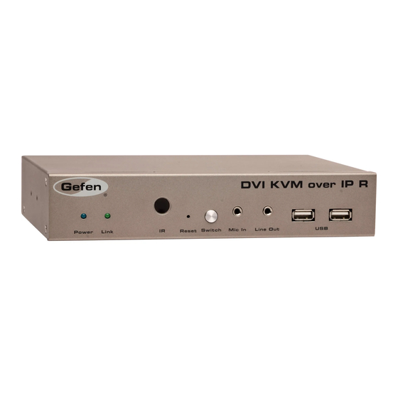
Page 14: Receiver Unit Layout
Getting Started Receiver Unit Layout Front Name Description Power This LED glows steady blue when the unit is connected to an AC outlet and the unit is powered ON. Link This LED glows steady green when the Sender and Receiver units are connected using Ethernet cable and successfully passing video. -
Page 15: Back
Sender unit) using an Ethernet cable. See the next page for installation instructions. IR Ext Connect an IR Extender cable (Gefen part no. EXT-RMT-EXTIRC or EXT-RMT-EXTIRN) to this port. 5V DC Connect the included 5V DC locking power supply to this power receptacle. -
Page 16: Installation
Getting Started Installation Page Title The DVI KVM over IP Sender and Receiver units can either be connected over a Local Area Network (LAN) or they can be directly connected to one another. Using a Direct Connection By default, the DVI KVM over IP is shipped in Auto IP mode. In Auto IP mode, each Sender and Receiver unit assigns itself a unique IP address within the range of 169.254.x.x. - Page 17 Getting Started Installation NOTE: When using HDMI sources with an HDMI-to-DVI adapter, the HDMI audio will be passed through to the DVI Out connector on the Receiver unit. Supplementary Connections for instruction on connecting USB, IR, RS-232, and audio cables. Connect the included 5V DC locking power supplies to the Sender unit and Receiver unit.
-
Page 18: Local Area Network (Lan) Connection
Getting Started Installation Local Area Network (LAN) Connection IMPORTANT: The use of a Gigabit switch with 8K “jumbo frame” capability is required when connecting the DVI KVM over IP to a network. In order to connect the DVI KVM over IP to a Local Area Network (LAN), both the Sender and Receiver unit must first be set to DHCP mode or static IP mode. - Page 19 Getting Started Installation Disconnect the cable between the Sender and Receiver unit. Connect the cable from the Sender unit to the network. Sender unit Connect to LAN Receiver unit Connect to LAN / DHCP server Note that any LAN port on the Receiver unit can be used to connect to the LAN. page | 9...
-
Page 20: Supplementary Connections
Connect up to two USB devices to the Receiver unit. ► Connect a Gefen IR Emitter (Gefen part no. EXT-2IREMIT) to the Sender unit and attach it to the IR sensor on the device to be controlled. Connect an IR Extender (Gefen part no. EXT-RMT-EXTIRC or EXT-RMT-EXTIRN) to the Receiver unit if the IR sensor will not be within line-of-site for proper IR control. -
Page 21: Sample Wiring Diagram
USB CABLE Gigabit Switch AUDIO CABLE MIC CABLE RS-232 CABLE IR EMITTER Receiver IR EXTENDER Multimedia PC IR Emitter Microphone RS-232 Controlled USB Mouse Device USB Keyboard IR Extender Sender Powered Speakers or headphones HD Display EXT-DVIKVM-LAN page | 11... -
Page 23: Operating The Dvi Kvm Over Ip
Over 02 Operating the DVI KVM over IP... -
Page 24: Basic Operation
Operating the DVI KVM over IP Basic Operation Displaying the IP Address If the IP address(es) of a Sender and/or Receiver unit are not known, then use the following procedure to display the IP address of any Sender or Receiver unit on the network. Press and release the Switch button on the front panel of the Receiver unit. - Page 25 Operating the DVI KVM over IP Basic Operation Channel:1 After a few moments, the screen will go blank and the IP address of both the Sender and Receiver unit will be displayed in the lower-right corner of the screen. Local IP = Receiver unit Channel:1 FW: 12-Dec-24 b6e4 Local IP: 169.254.8.168...
-
Page 26: Settings The Ip Mode
Operating the DVI KVM over IP Basic Operation Setting the IP Mode The DVI KVM over IP can be set to Auto IP, DHCP, or Static IP mode. By default, the DVI KVM over IP is shipped in Auto IP mode. Access the Web interface by entering the IP address of the desired Sender or Receiver unit. -
Page 27: Setting The Video Channel
Operating the DVI KVM over IP Basic Operation Setting the Video Channel In order a Sender and Receiver unit to communicate with one another, they must both be set to the same channel. This is similar to changing the channel on a cable or satellite box in order to view a different program. -
Page 28: Enabling Or Disabling Video Over Ip
Operating the DVI KVM over IP Basic Operation Enabling or Disabling Video over IP This feature is useful for masking video. Disabling the video on the Sender unit will mask the video on all connected Receiver units (multicast mode only). To mask the video on selected Receiver units, disable the video on the desired Receiver units. -
Page 29: Unicast And Multicast Modes
Operating the DVI KVM over IP Unicast and Multicast Modes Configuring Unicast Mode The term unicast is used to describe a configuration where information is sent from one point to another point. It is possible to have multiple Sender and Receiver units connected in a system. - Page 30 Operating the DVI KVM over IP Unicast and Multicast Modes Click the Unicast button under the Network Mode group. When selected, the Unicast button will be highlighted in blue. Click the Save button in the lower-right corner of the Network Mode group. The following message will be displayed, at the top of the page, indicating that the casting mode has been applied to the Sender or Receiver unit.
-
Page 31: Switching Between Sender Units In Unicast Mode
Operating the DVI KVM over IP Unicast and Multicast Modes Switching between Sender units in Unicast mode When multiple Sender and Receiver unit are used in unicast mode, the DVI KVM over IP behaves as a switcher. In unicast mode, a Sender unit can communicate with only one Receiver unit at a time. - Page 32 Operating the DVI KVM over IP Unicast and Multicast Modes Figure 2.3 - Unicast mode: Receiver unit R1 is now connected to Sender unit S1. Receiver unit DVI Out Sender unit DVI Out Receiver unit Sender unit DVI In Sender unit DVI In DVI In Note that each of the Sender units in Figure 2.3 is assigned a unique channel number.
- Page 33 Operating the DVI KVM over IP Unicast and Multicast Modes In order to solve the problem, in Figure 2.4, we would need to make sure that each of the Sender units is set to a unique channel number. When using unicast mode, each of the Sender units must be assigned a unique channel and should never be changed.
-
Page 34: Configuring Multicast Mode
Operating the DVI KVM over IP Unicast and Multicast Modes Configuring Multicast Mode The term multicast is used to describe a configuration where information is sent from one or more points to a set of other points. For example, a single Sender unit can transmit data to multiple Receiver units. - Page 35 Operating the DVI KVM over IP Unicast and Multicast Modes Click the Multicast button under the Network Mode group. When selected, the Multicast button will be highlighted in blue. Click the Save button in the lower-right corner of the Network Mode group. The following message will be displayed, at the top of the page, indicating that the casting mode has been applied to the Sender or Receiver unit.
-
Page 36: Using Rs-232
RS-232 data must be set to the same baud rate as the RS-232 host and client. In the example below, the Gefen 4x1 HD Switcher w/ Audio Decoding (Gefen part no. GTV-AUDDEC-N) has been connected to Receiver unit A. This is the RS-232 client. - Page 37 Operating the DVI KVM over IP Using RS-232 Access the Web interface for the Sender unit. Click the Functions tab. Locate the Serial over IP group and change the RS-232 settings to match the settings of the RS-232 device that is being used. In this case, we need to use the settings from Table 2.1 Make sure that the Enable Serial over IP box is checked.
-
Page 38: Rs-232 Under Unicast Mode
Operating the DVI KVM over IP Using RS-232 RS-232 under Unicast Mode In unicast mode, a Sender unit will be able to communicate with only one Receiver unit at a time. Figure 2.7 - In unicast mode, the host can talk to only one RS-232 device at a time. Receiver unit DVI Out C -N... -
Page 39: Usb Control
Operating the DVI KVM over IP USB Control USB under Unicast Mode When connecting USB devices to the DVI KVM over IP, the functionality is similar to that of video and RS-232. NOTE: By default, the DVI KVM over IP Sender and Receiver units are shipped in unicast mode. - Page 40 Operating the DVI KVM over IP USB Control Locate the USB over IP group and make sure the Enable USB over IP box is checked. This is the default setting. In unicast mode, the Operation Mode is automatically set to Active on link and cannot be changed.
-
Page 41: Usb Under Multicast Mode
Operating the DVI KVM over IP USB Control USB under Multicast Mode When connecting USB devices to the DVI KVM over IP, the functionality is similar to that of video and RS-232. There are two USB modes available in multicast mode: Active per request mode and Active on link mode. - Page 42 Operating the DVI KVM over IP USB Control In multicast mode, the Operation Mode for both Sender and Receiver units are automatically set to Active per request mode. Under Active per request mode, multiple USB devices may be present on one or more Receiver units.
- Page 43 Operating the DVI KVM over IP USB Control Assigning USB control under Active per request mode Press and hold the Switch button on the desired Receiver unit, for at least two seconds. In this example, we will depress the Switch button on Receiver unit R1. The message “Starting USB”...
- Page 44 Operating the DVI KVM over IP USB Control Active on link mode Under Active on link mode, a maximum of four USB devices can be used within a system. In the diagram, on the previous page, the system is already using the maximum number of USB devices (2 USB devices per Receiver).
-
Page 45: Edid Management
Operating the DVI KVM over IP EDID Management The DVI KVM over IP features EDID Management. Before the source can send video (and/or audio) data, the source device (connected to each Sender unit) reads the EDID (Extended Display Identification Data) from the displays which are connected to each Receiver unit. -
Page 46: Using The Downstream Edid
Operating the DVI KVM over IP EDID Management Using the Downstream EDID By default, the (downstream) EDID from the display, connected to the Receiver unit, is used. If the internal EDID is being used (see Using the Internal DVI EDID), then use the following procedure to revert to the downstream EDID. -
Page 47: Audio Connections
Operating the DVI KVM over IP Audio Connections Audio works in both unicast and multicast modes. The only difference between the two modes is that the Mic In jack is automatically disabled, on all Receiver units, in multicast mode. To illustrate how audio works with the DVI KVM over IP, we will set up a microphone and some speakers. - Page 48 Operating the DVI KVM over IP Audio Connections Finally, we’ll connect a set of powered computer speakers to the Line Out jack on the Receiver unit. Connect to computer speakers In the diagram below, the mouse and keyboard USB devices have been removed from Sender unit S2 and Receiver unit R2, for purposes of clarity.
-
Page 49: Using Hdmi Sources
Operating the DVI KVM over IP Audio Connections Figure 2.13 - The Mic In jack, on all Receiver units, is automatically disabled in multicast mode. Microphone Powered speakers Receiver unit Powered speakers Mic In Line Out Sender unit Receiver unit Line Out Sender unit DVI In... -
Page 50: Setting The Video Mode
Operating the DVI KVM over IP Setting the Video Mode The DVI KVM over IP provides two video modes: Video Mode and Graphic Mode. Consecutively pressing the Mode button on the Sender unit will toggle between Video Mode and Graphic Mode. ►... -
Page 51: Performing A Factory Reset
Operating the DVI KVM over IP Performing a Factory Reset To reset a DVI KVM over IP Sender and / or Receiver unit to factory-default settings, follow the instructions below. Sender Unit Disconnect the power from the Sender unit. Press and hold the Mode button. While continuing to press the Mode button, reconnect the power. -
Page 53: 03 Appendix
Over 03 Appendix... -
Page 54: Upgrading The Firmware
• Computer (Mac or PC) • Firmware files Download the firmware for the DVI KVM over IP from the Gefen Web site. Extract both firmware files from the .ZIP file. The .ZIP file contains two files: ► TX_host_kernel_A511_webfwh_v[version]d.bin (Sender unit) ►... - Page 55 Appendix Upgrading the Firmware Once the firmware upgrade process has completed, the DVI KVM over IP will reboot. Repeat the process for each Sender and Receiver unit in the system. page | 45...
-
Page 56: Developer Notes
Appendix Developer Notes The following information is intended for developers that use the DVI KVM over IP product as part of their application. To change the routing on the Sender and Receiver unit, the following URL needs to be issued: http://IP/cgi-bin/query.cgi?callback=jQuery15101605335909232362_1 370475364360&cache=false&nocache=1370480983843&cmd=astparam+s+mul ticast_ip+225.0.100.inpStr%3Bastparam+s+ch_select+inp%3Bast_send_... -
Page 57: Network Cable Diagram
Shielded (STP) CAT-5 or CAT-6 is recommended. However, unshielded (UTP) CAT-5 or CAT-6 is acceptable. CAT-5, CAT-5e, and CAT-6 cabling comes in stranded and solid core types. Gefen recommends using solid core cabling. CAT-6 cable is also recommended. It is recommended to use one continuous run from one end to the other. Patch cable is not recommended. -
Page 58: Rack Tray Installation
Appendix Rack Tray Installation The following illustrations provide instructions for installing the Sender and/or Receiver unit(s) in the Gefen 1U Rack Tray (Gefen part no. EXT-RACK-1U). Step 1 Step 2 Turn unit upside down. Remove rubber feet. Step 3 Step 4 Line up holes on unit and rack tray. -
Page 59: Specifications
Appendix Specifications Supported Formats Resolutions (max.) • 1080p Full HD • 1920 x 1200 (WUXGA) Electrical Maximum Pixel Clock • 165 MHz Link indicator (Sender / Receiver) • 1 x LED, green Power indicator (Sender / Receiver) • 1 x LED, blue Connectors Video Input (Sender) •... - Page 60 Appendix Specifications Operational Power Input (Sender / Receiver) • 1 x 5V DC, locking Power Consumption (Sender / Receiver) • 10W (max.) Physical Dimensions (W x H x D) • 8.4” x 1.7” x 4.5” (Sender / Receiver) (213mm x 43mm x 113mm) Unit Weight (each unit) •...
- Page 62 Stretch it, Switch it, Split it, Control it. Gefen’s got it. ® 20600 Nordhoff St., Chatsworth CA 91311 1-800-545-6900 818-772-9100 fax: 818-772-9120 www.gefen.com support@gefen.com This product uses UL or CE listed power supplies.
Need help?
Do you have a question about the EXT-DVIKVM-LAN and is the answer not in the manual?
Questions and answers