Table of Contents
Advertisement
Quick Links
Advertisement
Table of Contents

Related Manuals for Gefen EXT-VGAKVM-LAN


Summary of Contents for Gefen EXT-VGAKVM-LAN
- Page 1 Over 3GSDI Audio Embedder EXT-VGAKVM-LAN User Manual Release A3...
-
Page 2: Important Safety Instructions
VGA KVM over IP Important Safety Instructions GENERAL SAFETY INFORMATION Read these instructions. Keep these instructions. Heed all warnings. Follow all instructions. Do not use this product near water. Clean only with a dry cloth. Do not block any ventilation openings. Install in accordance with the manufacturer’s instructions. -
Page 3: Warranty Information
Gefen warrants the equipment it manufactures to be free from defects in material and workmanship. If equipment fails because of such defects and Gefen is notified within two (2) years from the date of shipment, Gefen will, at its option, repair or replace the equipment, provided that the equipment has not been subjected to mechanical, electrical, or other abuse or modifications. - Page 4 8:00 AM to 5:00 PM Monday - Friday, Pacific Time VGA KVM over IP is a trademark of Gefen, LLC. Important Notice Gefen, LLC reserves the right to make changes in the hardware, packaging, and any accompanying documentation without prior written notice. © 2013 Gefen, LLC. All Rights Reserved.
- Page 5 • The Gefen VGA KVM over IP features the ability to generate compatible EDID and Hot Plug signals when working with different brands of source devices and monitors. IMPORTANT: The use of a Gigabit switch is required when connecting the VGA KVM over IP to a network.
- Page 6 VGA KVM over IP Operating Notes Type Sender A D Receiver Description (Host) (Client) type 1 X D 6752 type 2 6752 A X Type Sender A D Receiver Description (Host) (Client) upstream IR over IP data 18771 A X UDP / MC downstream IR over IP data X D 18770...
-
Page 7: Packing List
Packing List The VGA KVM over IP ships with the items listed below. If any of these items are not present in the box when you first open it, immediately contact your dealer or Gefen. • 1 x VGA KVM over IP (Sender unit) •... -
Page 8: Table Of Contents
3GSDI Audio Embedder VGA KVM over IP Table of Contents Getting Started Sender Panel Layout ..................... 2 Front ......................2 Back ......................3 Bottom ......................4 Receiver Panel Layout ..................5 Front ......................5 Back ......................6 Installation ......................7 Connecting to a Local Area Network (LAN) .......... -
Page 11: 01 Getting Started
Over 01 Getting Started Sender Panel Layout ..................... 2 Front ......................2 Back ......................3 Bottom ......................4 Receiver Panel Layout ..................5 Front ......................5 Back ......................6 Installation ......................7 Connecting to a Local Area Network (LAN) ..........7 Direct Connection .................. -
Page 12: Sender Panel Layout
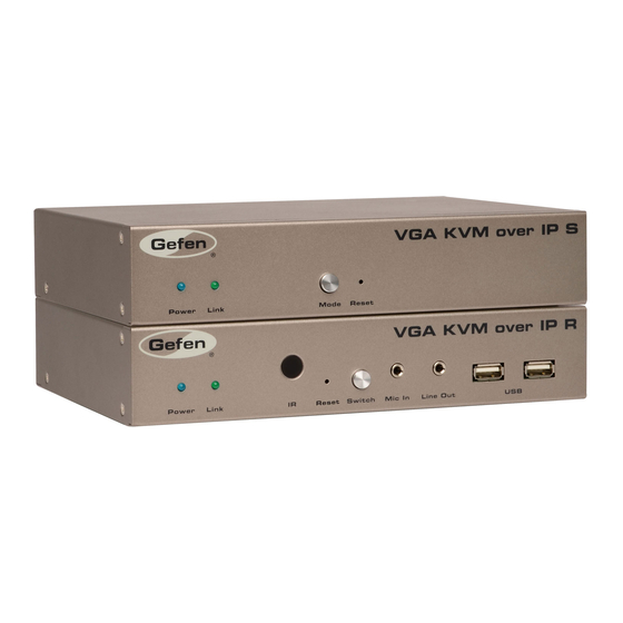
Getting Started Sender Panel Layout Front Name Description Power This LED glows bright blue when the unit is connected to an AC outlet and the unit is powered ON. Link This LED glows bright green when the Sender unit and Receiver unit are connected using Ethernet cable. -
Page 13: Back
Connects the Sender unit to the network (or directly to the Receiver unit) using an Ethernet cable. IR Out Connect an IR Blaster cable (Gefen part no. EXT-2IREMIT) from this port to the VGA source to control the source from the viewing location. -
Page 14: Bottom
Getting Started Sender Panel Layout Bottom Name Description Rotary switch Used to set the video channel for the Sender unit. Each Sender unit can be set to a different channel. See Setting the Video Channel for details. page | 4... -
Page 15: Receiver Panel Layout
Getting Started Receiver Panel Layout Front Name Description Power This LED glows bright blue when the unit is connected to an AC outlet and the unit is powered ON. Link This LED glows bright green when the Sender unit and Receiver unit are connected using CAT-5 / CAT-6 cable. -
Page 16: Back
Sender unit) using an Ethernet cable. See the next page for installation instructions. IR Ext Connect an IR Extender cable (Gefen part nos. EXT-RMT-EXTIRC or EXT-RMT-EXTIRN) from this port to extend the IR control distance. 5V DC Connect the included 5V DC locking power supply to this power receptacle. -
Page 17: Installation
Getting Started Installation Page Title The VGA KVM over IP Sender and Receiver units can either be connected over a Local Area Network or they can be directly connected to one another. Connecting to a Local Area Network (LAN) Connect a CAT-5e (or better) cable between the Link jack on the Sender unit and your LAN connection, via a switch or router. -
Page 18: Supplementary Connections
Connect up to two USB devices to the Receiver unit. ► Connect a Gefen IR Emitter (Gefen part no. EXT-2IREMIT) to the Sender unit and attach it to the IR sensor on the device to be controlled. Connect an IR Extender (Gefen part no. EXT-RMT-EXTIRC or EXT-RMT-EXTIRN) to the Receiver unit if the IR sensor will not be within line-of-site for proper IR control. -
Page 19: Sample Wiring Diagram
USB CABLE AUDIO CABLE Gigabit Switch MIC CABLE RS-232 CABLE IR EMITTER IR EXTENDER Receiver Multimedia PC IR Emitter Microphone RS-232 Controlled USB Mouse Device USB Keyboard IR Extender Sender Powered Speakers or headphones VGA Display EXT-VGAKVM-LAN page | 9... -
Page 21: Operating The Vga Kvm Over Ip
Over 02 Operating the VGA KVM over IP The Linking Process .................... 12 Network Configuration ..................13 Accessing the Web Interface ..............13 Configuring Auto IP Mode ................15 Changing Network Settings on the Computer ..........18 Configuring Static IP Mode ................. 22 Configuring DHCP Mode ................ -
Page 22: The Linking Process
Operating the VGA KVM over IP The Linking Process By default, the VGA KVM over IP is shipped in DHCP mode. DHCP mode should work in most cases, since the Sender and Receiver units are assigned an IP address by the DHCP server or router. -
Page 23: Network Configuration
Operating the VGA KVM over IP Network Configuration If DHCP mode is not desired, the VGA KVM over IP can also be set to Auto IP mode or Static IP mode. In order to change the network options, both the Sender and Receiver unit contain a built-in Web interface. - Page 24 Operating the VGA KVM over IP Network Configuration The following page will be displayed: “h” identifies this page as the Sender (host) unit. Open another tab or window in the Web browser and enter the IP address of the Receiver (client) unit. The page for the Receiver unit will appear very similar to that of the Sender unit.
-
Page 25: Configuring Auto Ip Mode
Operating the VGA KVM over IP Network Configuration Configuring Auto IP Mode Auto IP mode is used when there is no DHCP server (or router) available and each Sender and Receiver unit is connected to a switch. When set to Auto IP mode, the Sender and Receiver unit will self-assign unique IP addresses (within the range of 169.254.x.x). - Page 26 Operating the VGA KVM over IP Network Configuration Type the following command in the Console API Command text box: astparam s ip_mode autoip; astparam save; Click the Apply button. The “Loading” message will appear, indicating that the commands are being executed. “Loading”...
- Page 27 Operating the VGA KVM over IP Network Configuration Although this message will be presented when there is an error in the command line, it is important to understand that this also occurs after the network mode has been changed. This is because the IP address has changed and the Web page can no longer access the current IP address of the Sender (or Receiver) unit.
-
Page 28: Changing Network Settings On The Computer
Operating the VGA KVM over IP Network Configuration Changing Network Settings on the Computer We just finished configuring the Sender and Receiver units to Auto IP mode. In order to configure these units for Static IP mode (or to return to DHCP mode), we will need to configure each unit separately. - Page 29 Operating the VGA KVM over IP Network Configuration Double-click on the Local Area Connection icon to display the Local Area Connection Status dialog. Click the Properties button. Click on Internet Protocol Version 4 (TCP/IPv4). page | 19...
- Page 30 Operating the VGA KVM over IP Network Configuration Click the Properties button to display the Internet Protocol Version 4 (TCP/IPv4) Properties dialog. STOP: If the computer that is connected does not use Obtain an IP address automatically and Obtain DNS server address automatically, write down the current IP settings before making changes, in order to restore them later.
- Page 31 Operating the VGA KVM over IP Network Configuration Click the OK button, then close all Control Panel windows. 10. Launch a Web browser and type in the IP address for the Sender unit. In our example, the IP address for the Sender unit is 169.254.7.8 11.
-
Page 32: Configuring Static Ip Mode
Operating the VGA KVM over IP Network Configuration Configuring Static IP Mode Access the Web interface of the Sender (host) unit by entering the IP address of the Sender (or Receiver) unit in a Web browser. See Accessing the Web Interface. -
Page 33: Setting The Video Channel
Operating the VGA KVM over IP Setting the Video Channel In order for the Receiver unit to acquire the desired source (connected to the Sender unit), the Sender and Receiver unit(s) must be set to the same channel. It’s very similar to changing the channel on a cable box or television. - Page 34 Operating the VGA KVM over IP Setting the Video Channel Reboot the Sender unit for the channel-change to take effect. Rebooting the Sender unit (or the Receiver unit) can be performed in one of two ways: 1) Disconnect and reconnect the power supply. 2) Click the Reboot button on the Web interface. Press the Switch button on the front panel of the Receiver unit.
- Page 35 Operating the VGA KVM over IP Setting the Video Channel Once the current channel is displayed, consecutively press the Switch button on the front panel of the Receiver unit until “Channel 02” is displayed. If the channel is not changed within a specific amount of time, the current channel setting will disappear from the screen.
-
Page 36: Unicast And Multicast Modes
Operating the VGA KVM over IP Unicast and Multicast Modes The VGA KVM over IP has two operating modes: Unicast and multicast. In unicast mode, only a single Receiver unit can display video using multiple (or a single) Sender unit on the same network. - Page 37 Operating the VGA KVM over IP Unicast and Multicast Modes Click the Network tab and click the Unicast button. When selected, the Unicast button will be highlighted in green. Click the Apply button. page | 27...
- Page 38 Operating the VGA KVM over IP Unicast and Multicast Modes A message will be displayed, indicating that the casting mode has been applied to the Receiver unit. After a few moments, another message will be displayed stating that the Receiver unit must be rebooted in order for the new settings to take effect.
- Page 39 Operating the VGA KVM over IP Unicast and Multicast Modes Reboot the Receiver unit by one of these methods: 1) Disconnect and reconnect the power supply. 2) Click the Reboot button on the Web interface. Repeat steps 1 through 6 for each Sender and Receiver on the network. Now that each device has been configured, we need to specify which channels will be used by each Sender and Receiver unit.
-
Page 40: Switching Between Displays In Unicast Mode
Operating the VGA KVM over IP Unicast and Multicast Modes Switching between displays in Unicast mode In order to control which display receives the source signal, press the Switch button on the Receiver unit to change the channel. For example, let’s say we want to send the VGA source to Receiver unit A. - Page 41 Operating the VGA KVM over IP Unicast and Multicast Modes Channel:02 FW: 12-Dec-24 b6e4 Local IP: 192.168.1.8 Remote IP: 192.168.1.7 Trying to find the gateway... ID: 82B9969C6B9E To release Receiver unit B from receiving the VGA source signal, press the Switch button and change the channel on Receiver unit B to something other than channel 02.
-
Page 42: Configuring Multicast Mode
Operating the VGA KVM over IP Unicast and Multicast Modes Configuring Multicast Mode NOTE: When using multicast mode, use a Gigabit switch with “Jumbo Frame” capability (enabled) to ensure the best video quality. To illustrate an example of how multicast mode works, we will use the same diagram that was used in Configuring Unicast Mode. -
Page 43: Using Rs-232
In addition, the correct baud rate must be set on the Sender and Receiver units which are being used to control the RS-232 client. In the example below, the Gefen 4x1 HD Switcher w/ Audio Decoding (Gefen part no. GTV-AUDDEC-N) has been connected to Receiver unit A. This is the RS-232 client. - Page 44 Operating the VGA KVM over IP Unicast and Multicast Modes NOTE: If the Enable Serial over IP is not checked, then RS-232 pass-through will be disabled. Select the baud rate of the RS-232 controller by selecting it from the drop-down list in the Baudrate field.
- Page 45 Operating the VGA KVM over IP Unicast and Multicast Modes A message will be displayed, indicating that the new Serial over IP settings have been applied to the Sender unit. After a few moments, another message will be displayed stating that the Sender unit must be rebooted in order for the new settings to take effect.
- Page 46 When using multicast mode, multiple Receiver units will be able to communicate with the RS-232 host (Computer) device. For instance, if we expand on our original example by connecting a Gefen 4x1 HD Switcher to Receiver A, B, and C (not shown), then we could control all three devices simultaneously.
-
Page 47: Usb Control
Operating the VGA KVM over IP Unicast and Multicast Modes USB Control When connecting USB devices to the VGA KVM over IP, the functionality is similar to that of video and RS-232. As an example, we will connect a computer to the Sender unit 2 and a mouse device to Receiver unit B. -
Page 48: Audio Input And Output
Operating the VGA KVM over IP Unicast and Multicast Modes ► Unicast Mode In unicast mode, only a single Receiver unit will be able to communicate with a Sender unit. However, multiple USB devices can be connected to multiple Receiver units. - Page 49 Operating the VGA KVM over IP Unicast and Multicast Modes WARNING: DO NOT connect the cable from the Line Out jack on the Sender unit to the Mic In jack on the computer. Doing so will result in audio “clipping” and may cause damage to the sound card. Connect to Line Out on computer Sender unit...
- Page 50 Operating the VGA KVM over IP Unicast and Multicast Modes Let’s take a look at our setup. All new audio connections that were made are highlighted in blue. We could also have connected a Blu-ray player, instead of the multimedia PC (indicated by the dark-blue dashed line).
-
Page 51: Disabling / Enabling Video
Operating the VGA KVM over IP Unicast and Multicast Modes Disabling / Enabling Video This can be useful when ‘masking’ video which prevents it from being displayed. This feature is available under the Functions tab on both the Sender (host) and Receiver (client) Web interface, as shown below. -
Page 52: Video Modes
Operating the VGA KVM over IP Video Modes The VGA KVM over IP provides two video modes: Video Mode and Graphic Mode. Consecutively pressing the Mode button on the Sender unit will toggle between Video Mode and Graphic Mode. If the VGA signal is a video source, press the Mode button on the front panel of the •... -
Page 53: Edid Management
Operating the VGA KVM over IP EDID Management The VGA KVM over IP features EDID Management. Before the source can send video (and/or audio) data, the source device (connected to each Sender unit) reads the EDID (Extended Display Identification Data) from the displays which are connected to each Receiver unit. - Page 54 Operating the VGA KVM over IP EDID Management Sender unit Make sure this box is not checked NOTE: Selecting or deselecting any check box within the Web interface will not automatically enable or disable the feature. Always click the Apply button then reboot the unit to save the changes Access the Web interface for the Receiver unit that is connected to Display B.
- Page 55 Operating the VGA KVM over IP EDID Management Click the Apply button within the Video over IP section. Reboot the Receiver unit by one of these methods: 1) Disconnect and reconnect the power supply. 2) Click the Reboot button on the Web interface. The EDID from Display B will now be used by the Sender unit (Sender 3).
-
Page 56: Restoring The Default Edid
Operating the VGA KVM over IP EDID Management Restoring the Default EDID Beginning with our last example (see diagram on previous page), we will restore the default VGA EDID used by the Sender unit (used when the unit is shipped). Access the Web interface for Receiver unit B which was used to transmit the EDID to the Sender unit. - Page 57 Operating the VGA KVM over IP EDID Management Click the Apply button within the Video over IP section. Reboot the Sender unit. The default EDID (within the Sender unit) will now be used by read by each display. When each display reads the EDID of the VGA source, it will read the default VGA EDID stored in the Sender unit.
-
Page 59: 03 Appendix
Over 03 Appendix Network Cable Diagram ..................50 Rack Tray Installation ..................51 Specifications ...................... 52... -
Page 60: Network Cable Diagram
Appendix Network Cable Diagram Front of RJ-45 Connector 1 2 3 4 5 6 7 8 Gefen recommends the TIA/EIA-568-B wiring option. Use the table below when field-terminating cable for use with Gefen products. Color Description Orange / White TD+ (Transmit Data, positive differential signal) -
Page 61: Rack Tray Installation
Appendix Rack Tray Installation The following illustrations provide instructions for installing the Sender and/or Receiver unit(s) in the Gefen 1U Rack Tray (Gefen part no. EXT-RACK-1U). Step 1 Step 2 Turn unit upside down. Remove rubber feet. Step 3 Step 4 Line up holes on unit and rack tray. -
Page 62: Specifications
Appendix Specifications Supported Formats Resolution (max.) • 1920 x 1200 (WUXGA) Electrical Maximum Pixel Clock • 350 MHz Link indicator (Sender / Receiver) • 1 x LED, green Power indicator (Sender / Receiver) • 1 x LED, blue Connectors Video Input (Sender) •... - Page 63 Appendix Specifications Operational Power Input (Sender / Receiver) • 1 x 5V DC, locking Power Consumption (Sender / Receiver) • 10W (max.) Physical Dimensions (W x H x D) • 8.4” x 1.7” x 4.5” (Sender / Receiver) (213mm x 43mm x 113mm) Unit Weight (each unit) •...
- Page 64 Stretch it, Switch it, Split it, Control it. Gefen’s got it. ® 20600 Nordhoff St., Chatsworth CA 91311 1-800-545-6900 818-772-9100 fax: 818-772-9120 www.gefen.com support@gefen.com This product uses UL or CE listed power supplies.
Need help?
Do you have a question about the EXT-VGAKVM-LAN and is the answer not in the manual?
Questions and answers