Table of Contents
Advertisement
Quick Links
Advertisement
Table of Contents

Related Manuals for Owon ADS802A


Summary of Contents for Owon ADS802A
- Page 1 ADS800A Series Quick Guide ADS802A/804A ADS812A/814A ADS822A/824A For product support, visit:www.owon.com.hk/download ※:The illustrations, interface, icons and characters in the user manual may be slightly different from the actual product. Please refer to the actual product.
- Page 2 LILLIPUT Company. Fujian LILLIPUT Optoelectronics Technology Co., Ltd. No. 19, Heming Road Lantian Industrial Zone, Zhangzhou 363005 P.R. China Tel: +86-596-2130430 Fax: +86-596-2109272 Web: E-mail: www.owon.com.cn info@owon.com.cn...
-
Page 3: Table Of Contents
Table of Contents 1. General Safety Requirements ............1 2. Safety Terms And Symbols ..............3 How To Conduct A General Inspection .................5 How To Conduct Function Inspection ................... 6 3. Primary User Guide ................7 A General Knowledge Of The Structure Of The Instrument ..........8 Front Panel ........................8 Rear Panel ........................ -
Page 4: General Safety Requirements
1.General Safety Requirements 1.General Safety Requirements Before use, please read the following safety precautions to avoid any possible bodily injury and to prevent this product or any other connected products from damage. In order to avoid any contingent danger, ensure this product is only used within the range specified. - Page 5 1.General Safety Requirements instrument. Avoid exposed circuit. Do not touch exposed junctions and components when the instrument is powered. Do not operate if in any doubt. If you suspect damage occurs to the instrument, have it inspected by qualified service personnel before further operations.
-
Page 6: Safety Terms And Symbols
2.Safety Terms And Symbols 2.Safety Terms And Symbols Safety Terms Terms in this manual. The following terms may appear in this manual: Warning: Warning indicates the conditions or practices that could result in injury or loss of life. Caution: Caution indicates the conditions or practices that could result in damage to this product or other property. - Page 7 2.Safety Terms And Symbols To avoid body damage and prevent product and connected equipment damage, carefully read the following safety information before using the test tool. This product can only be used in the specified applications. Warning The four channels of the oscilloscope are not electrically isolated. The channels should adopt a common ground during measuring.
-
Page 8: How To Conduct A General Inspection
2.Safety Terms And Symbols Warning: To avoid fire or electrical shock, when the oscilloscope input signal connected is more than 42V peak (30Vrms) or on circuits of more than 4800VA, please take note of below items: Only use accessory insulated voltage probes and test lead. ... -
Page 9: How To Conduct Function Inspection
2.Safety Terms And Symbols responsible for this service or our local offices. 3. Check the Complete Instrument. If it is found that there is damage to the appearance of the instrument, or the instrument can not work normally, or fails in the performance test, please get in touch with our distributor responsible for this business or our local offices. -
Page 10: Primary User Guide
3.Primary User Guide 3.Primary User Guide The following are illustrated with four channels as an example, and for two channels, please refer to four channels. Model Channel ADS802A ADS804A ADS812A ADS814A ADS822A ADS824A This chapter elaborates the following topics: A general knowledge of the structure of the instrument ... -
Page 11: A General Knowledge Of The Structure Of The Instrument
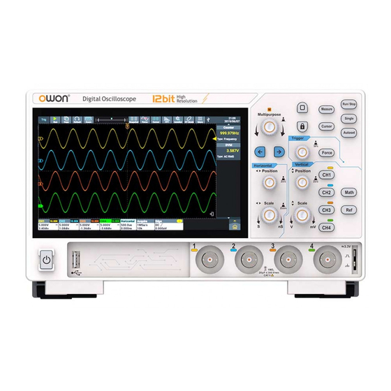
3.Primary User Guide A General Knowledge Of The Structure Of The Instrument This chapter gives a brief description and introduction to the operations and functions of the front panel of the instrument, so as to facilitate your operations of the instrument in the shortest time. Front Panel On the instrument panel, knobs and function buttons are used to enter different function menus or directly use specific function application. - Page 12 3.Primary User Guide turned to set the value. Example can rotate the knob to change the offset value. Arrow keys : Move to select the parameter. Home key : Return to the main homepage. Touch key : Press it to disable the touch screen, the key light turns on;...
-
Page 13: Rear Panel
3.Primary User Guide “Horizontal Scale” knob is to control time base scale. 6. Probe compensation: about 3.3V/1kHz signal output. 7. Channel input port area. 8. USB Host Interface: When the oscilloscope is connected to an external USB device as a “master device”, the USB Host interface is used to transmit the data (Note: the devices that can be connected include a mouse, keyboard, USB flash drive, etc.). -
Page 14: A General Knowledge Of The User Interface Of The Instrument
3.Primary User Guide USB device as a “slave device”, the USB Device interface is used to transmit the data. For example, use the interface to connect a PC. 5. HDMI Interface: To connect HDMI output to the external monitor or projector. - Page 15 3.Primary User Guide enabled and connected currently). Click the icon will switch to the Wireless&networks setting interface. 4. U disk access identifier. 5. System set time, click the icon will switch to the Date&time setting interface. 6. Counter and others function information display bar (Note: click the left corner corresponds to enable/disable statistic).
-
Page 16: Oscilloscope Inspection
3.Primary User Guide Oscilloscope Inspection 1. Set the Switch in the Oscilloscope Probe as 10X and Connect the Oscilloscope with CH1 Channel. Align the slot in the probe with the plug in the CH1 connector BNC, and then tighten the probe with rotating it to the right side. Connect the probe tip and the ground clamp to the connector of the probe compensator. -
Page 17: How To Set The Probe Attenuation Coefficient
3.Primary User Guide 1、 Set the attenuation coefficient of the probe in the menu as 10X and that of the switch in the probe as 10X (see "How to Implement the Probe Compensation" on P13), and connect the probe with the CH1 channel. If a probe hook tip is used, ensure that it keeps in close touch with the probe. -
Page 18: How To Use The Probe Safely
3.Primary User Guide (1) Click the channel information display bar on the bottom left of the screen (CH1 Channel, CH2 Channel, CH3 Channel or CH4 Channel). (2) Select Probe Attenu (1X,10X or other custom probe magnifications) in the displayed channel setting window. The setting will remain in effect until changed again after selection. -
Page 19: How To Conduct Self-Calibration
3.Primary User Guide Figure 3-8: Finger Guard Warning: To avoid electric shock, always keep your finger behind the safety guard ring of the probe during the operation. To protect you from suffering from the electric shock, do not touch any metal part of the probe tip when it is connected to the power supply. -
Page 20: Use The Android System
4.Use the Android System 4.Use the Android System Android System Homepage Window 1. Application shortcut key. If you click the oscilloscope shortcut key, you can enter the oscilloscope interface. 2. App Drawer (Click to see all apps). 3. Task key. 4. - Page 21 4.Use the Android System...
-
Page 22: Use The Oscilloscope
5.Use the Oscilloscope 5.Use the Oscilloscope A General Knowledge Of Trigger System As shown in Figure , there are one knob and one key. The following exercises are to guide you through the use of the trigger system. Figure 5-1: Trigger control area 1. -
Page 23: A General Knowledge Of Vertical System
5.Use the Oscilloscope Figure 5-2:Horizontal control area 1、 Rotary Horizontal Position knob to adjust the horizontal position of the signal in the waveform window. The Horizontal Position knob is to control the triggered horizontal position of the signal; when turning the knob, the waveform moves horizontally with the knob. - Page 24 5.Use the Oscilloscope Figure 5-3: Vertical control area 1. Vertical Position knob to control the vertical display position of the signal. When turning the Vertical Position knob, the pointer indicating the Grounding Reference Point of the channel moves up and down following the waveform.
-
Page 25: How To Use Touch Screen Control
5.Use the Oscilloscope through the information displayed in the information display bar at the lower part of the waveform window. Turn the Vertical Scale knob to change the Vertical Scale Factor (Voltage Scale), and the scale factor of corresponding channel in the information display bar changes accordingly. - Page 26 5.Use the Oscilloscope Set Menu Item:In the Settings window, you can change the configuration of the relevant menu item by touching it. The types of operable parts include: switch, button, radio, gear hobbing (scrolling list), etc. The following box selects the radio type, click directly to switch the options. ...
-
Page 27: Operate The Touch Screen
5.Use the Oscilloscope Operate The Touch Screen Select a Channel (CH1 channel,CH2 channel,CH3 channel or CH4 channel): Click the channel pointer on the left or click the channel waveform to make the channel pointer selected. Long press the channel pointer, the vertical position of waveform can be center (Note: Dual channel only have CH1 channel and CH2 channel). - Page 28 5.Use the Oscilloscope Set the trigger level of the signal source in the Trigger Menu (Trigger Level knob): The two grids on the right of the waveform area are the trigger level touch moving area, and the trigger level can be changed by sliding up and down in this area, as shown in the figure below.
- Page 29 5.Use the Oscilloscope The control voltage gear and time base can be scaled in the following way: In the waveform display area, up and down/left and right zoom thumb and index finger to zoom control voltage scale and time base, as shown in the figure below.
-
Page 30: Operate The Touch Screen In Waveform Amplification Mode
5.Use the Oscilloscope Operate The Touch Screen In Waveform Amplification Mode Press Horizontal Scale knob to enter the waveform zoom mode, the main window is displayed at the top half of the screen and the amplified window is displayed at the bottom half of the screen. The amplified window is the amplified part of the main window that is selected. -
Page 31: Other Touch Screen Operations
5.Use the Oscilloscope Other Touch Screen Operations Click and drag the open menu item to move itself to the appropriate location. Control the horizontal or vertical cursor lines under cursor measurement, as shown in the figure below. - Page 32 5.Use the Oscilloscope Run/Stop: Click in the upper left of the display area to switch Run/Stop. Parameter Setting Keyboard in Menu Item: There are digital input mode and hobbing input mode. Digital input mode, as shown in the figure below. Hobbing input mode, as shown in the figure below.
-
Page 33: How To Set Automatic Measurement
5.Use the Oscilloscope Swipe the information display bar How To Set Automatic Measurement Press the Measure button to perform automatic measurements. There are a total of 43 measurement types, and the screen can display up to 8 types of measurements at the bottom left corner. There are 43 kinds of measurement including:Period, + Width, Rise Time, +Duty, Frequency, - Width, Fall Time, -Duty, ScrDuty, Vavg, Vpp, Vamp, StdDev, Vmax, Vtop, VRMS, Overshoot, Vmin, Vbase, CycRms ,... - Page 34 5.Use the Oscilloscope Preshoot, +PulseCnt, -PulseCnt, RiseCnt, FallCnt, Area, CycArea, Delay(1 -2 ), Delay(1 -2 ), Delay(1 -2 ), Delay(1 -2 ), Phase(1 -2 ), Phase(1 -2 ), Phase(1 -2 ), Phase(1 -2 ), FRR(1 -2 ), FRF(1 -2 ), FFR(1 -2 ), FFF(1 -2 ), LRR(1 -2 ), LRF(1 -2 ), LFR(1 -2 ) and LFF(1 -2 ).
-
Page 35: Appendix
6.Appendix 6.Appendix Appendix A: Enclosure (The accessories subject to final delivery.) Standard Accessories: Power Cord Quick Guide USB Cable Probe Power Supply Adaptor Optional Accessories: BNC to alligator clip cable Appendix B: General Care And Cleaning General Care Do not store or leave the instrument where the liquid crystal display will be exposed to direct sunlight for long periods of time. - Page 36 6.Appendix 2. Disconnect power before cleaning your Oscilloscope. Clean the instrument with a wet soft cloth not dripping water. It is recommended to scrub with soft detergent or fresh water. To avoid damage to the instrument or probe, do not use any corrosive chemical cleaning agent. Warning: Before power on again for operation, it is required to confirm that the instrument has already been dried completely, avoiding any electrical short circuit or bodily injury resulting...
Need help?
Do you have a question about the ADS802A and is the answer not in the manual?
Questions and answers