Table of Contents
Advertisement
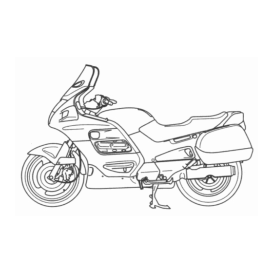
Owner's Manual Pan European ST1100(A) 1996+
IMPORTANT NOTICE
OPERATOR AND PASSENGER
This motorcycle is designed to carry the operator and one passenger. Never exceed the
maximum weight capacity as shown on the tyre information label.
ON-ROAD USE
This motorcycle is designed to be used only on the road.
READ THIS OWNER'S MANUAL CAREFULLY
Pay special attention to statements preceded by the following words:
Indicates a strong possibility of severe personal injury or death if instructions are not followed.
CAUTION:
Indicates a possibility of personal injury or equipment damage if instructions are not followed.
NOTE: Gives helpful information.
This manual should be considered a permanent part of the motorcycle and should remain with
the motorcycle when resold.
HONDA PAN EUROPEAN
ST1100
OWNER'S MANUAL
- Copyright for this owners manual only ©2011 LIFRASCHAL -
1
Advertisement
Table of Contents


Need help?
Do you have a question about the ST1100 1996+ and is the answer not in the manual?
Questions and answers