Table of Contents
Advertisement
Quick Links
Advertisement
Table of Contents

Related Manuals for Advantech ASMB-922I


Summary of Contents for Advantech ASMB-922I
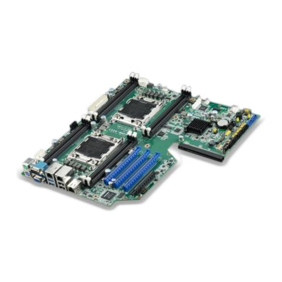
- Page 1 User Manual ASMB-922I ® Intel E5-2600(v2) Series Dual Processor EATX Server Board...
- Page 2 No part of this manual may be reproduced, copied, translated or transmitted in any form or by any means without the prior written permission of Advantech Co., Ltd. Information provided in this manual is intended to be accurate and reliable. How- ever, Advantech Co., Ltd.
- Page 3 Whether your new Advantech equipment is destined for the labo- ratory or the factory floor, you can be assured that your product will provide the reliability and ease of operation for which the name Advantech has come to be known.
-
Page 4: Declaration Of Conformity
Caution! There is a danger of a new battery exploding if it is incorrectly installed. Do not attempt to recharge, force open, or heat the battery. Replace the battery only with the same or equivalent type recommended by the man- ufacturer. Discard used batteries according to the manufacturer's instructions. ASMB-922I User Manual... - Page 5 02A1E link) ASMB-FF3PX- Advantech ASMB-FF3PX(PME board) 2*PCI-X + 1*PCI slot 12A1E ASMB-FF20F- 2*PCIe x16 slot(Gen3 x16 Advantech ASMB-FF20F(PME board) 02A1E link) 2*PCIe x8 slot(1*Gen2 x8 ASMB-FF3P8- Advantech ASMB-FF3P8(PME board) + 1*Gen2 x4 link) + 1*PCI 12A1E slot ASMB-922I User Manual...
- Page 6 It should be free of marks and scratches and in perfect working order upon receipt. When unpacking the ASMB-922I, check it for signs of shipping damage. (For example, damaged box, scratches, dents, etc.) If it is dam- aged or it fails to meet the specifications, notify our service department or local sales representative immediately.
-
Page 7: Table Of Contents
Clear CMOS Connector (JCMOS1) ............28 2.17 PMBUS Connector (PMBUS1)..............28 2.18 Front Panel SMBUS Connector (SMBUS1) ..........29 2.19 IPMI Module Connector (BMC1) ............. 30 2.20 VOLT1 Connector ................... 31 2.21 GPIO Connector..................32 Chapter AMI BIOS ..........33 ASMB-922I User Manual... - Page 8 Table B.3: RS-232 Interface (COM2) ........87 PS/2 Keyboard and Mouse Connector (KBMS1)........87 Table B.4: Keyboard and Mouse Connector (KBMS1) ....87 External Keyboard Connector (KBMS2) ..........88 Table B.5: External Keyboard Connector (KBMS2)....88 ASMB-922I User Manual viii...
- Page 9 8-pin Alarm Board Connector (VOLT1)........... 91 Table B.15:8-pin Alarm Board Connector (VOLT1) ....91 B.16 Case Open Connector (JCASE1) ............92 Table B.16:Case Open Connector (JFP1) ........92 B.17 Front Panel LAN LED Connector (LANLED1)......... 92 Table B.17:LAN LED Connector (LANLED1)......92 ASMB-922I User Manual...
- Page 10 ASMB-922I User Manual...
-
Page 11: Chapter 1 Overview
Chapter Overview... -
Page 12: Introduction
High reliability and outstanding performance makes ASMB-922I the ideal platform for industrial server/networking applications. By using the Intel C602J chipset, the ASMB-922I offers a variety of features such as 4 onboard SATA II, and 2 onboard SATA III interfaces; it supports IRST (Intel Rapid Storage Technology) and provides RAID 0, 1, 10 and 5 (Windows only*);... -
Page 13: Specifications
2 x RJ-45 LAN ports (10/100/1000 Base-T LAN). 1 x RJ-45 Dedicated IPMI LAN port(10/100 Base-T) for IPMI only, there is no regular LAN function (ASMB-922I SKU Only). 2 x USB3.0 + 2 x USB 2.0 ports at rear window. - Page 14 Non-operating Relative Humidity: 5% to 95% (non-condens- ing) Note! If you need more expansion slots, apply a PME to ASMB-922I. PMEs have different types and design flexibility for different interface expan- sion cards. Please visit Advantech official website to see what kind of PME can be used.
-
Page 15: Board Layout, Jumpers And Connectors
Board Layout, Jumpers and Connectors Connectors on the ASMB-922I are linked to external devices such as hard disk drives. In addition, ASMB-922I has a number of jumpers that are used to configure system for specific applications. The tables below list the functions of each jumper and connector. Later sections in this chapter give instructions for setting jumpers. -
Page 16: Figure 1.2 Rear I/O
Blinking green Link Amber Green Amber 100 Mbps Active Amber Blinking green Amber Blinking green Link Green Green 1000 Mbps Active Green Blinking green No Link Table 1.3: Jumpers Label Function Default JCMOS1 CMOS Clear JME1 ME update ASMB-922I User Manual... -
Page 17: Table 1.4: Connectors
Serial ATA5 hard drive connector (SATA II) SYS FAN0 System fan connector (4-pin) SYS FAN1 System fan connector (4-pin) SYS FAN2 System fan connector (4-pin) USB23 USB port 2, 3 USB45 USB port 4, 5 USB67 USB port 6, 7 ASMB-922I User Manual... -
Page 18: Table 1.5: Onboard Led
Table 1.4: Connectors USB89 USB port 8, 9 USB10 USB port 10 (Type-A) VOLT1 For Advantech alarm board usage PMBUS1 Power supply SMBbus I2C Header SATA_SGPIO_1 Support Serial_Link interface for onboard SATA connections GPIO1 GPIO function for customize usage SMBUS1... -
Page 19: System Memory
System Memory ASMB-922I has eight 240-pin memory slots for DDR3 1066/1333/1600 MHz memory modules with maximum capacity of 128 GB (Maximum 16 GB for each DIMM). ASMB-922I supports registered DIMMs or unbuffered DIMM with ECC / Non-ECC memory module. Memory Installation Procedures... - Page 20 Press the DIMM module right down into the socket, until you hear a click. This is when the two handles have automatically locked the memory module into the correct position of the DIMM socket. Step 4 Finished. ASMB-922I User Manual...
-
Page 21: Processor Installation
Processor Installation The ASMB-922I is designed for Intel E5-2600 series Xeon processor. Step 1 Press the first lever and move it sideways slightly until it is released from the reten- tion tab. Step 2 Press the other lever and move it sideways slightly until it is also released from the retention tab. - Page 22 Lift the load plate. Step 4 Position the CPU over the socket ensuring that the triangle mark on the CPU lines up with the triangle mark on the motherboard. Triangle mark Step 5 Remove protective plastic cover. ASMB-922I User Manual...
- Page 23 Step 6 Close the load plate over the CPU. Step 7 Push down both levers and insert them under the retention tabs ensuring the edge of the load plate is fixed securely by both levers. Step 8 Finished. ASMB-922I User Manual...
- Page 24 ASMB-922I User Manual...
-
Page 25: Chapter 2 Connections
Chapter Connections... -
Page 26: Introduction
Mbps (USB 2.0) / 5Gbps (USB 3.0) and fuse protection are supported. The USB interface can be disabled in the system BIOS setup. The ASMB-922I is equipped with two high-performance 1000 Mbps Ethernet LANs. They are supported by all major network operating systems. The RJ-45 jacks on the rear plate provide convenient 1000Base-T operation. -
Page 27: Vga Connector
VGA Connector The ASMB-922I includes a VGA interface that can drive conventional CRT and LCD displays. Serial Ports (COM1/COM2) The ASMB-922I offers 2 serial ports (One on the rear panel and one onboard). COM2 ASMB-922I User Manual... -
Page 28: Ps2 Keyboard And Mouse Connectors (Kbms1/Kbms2)
PS/2 keyboard and mouse connections. KBMS2 connector is for additional keyboard & mouse device usage. KBMS1 KBMS2 CPU Fan Connector (CPU FAN0/FAN1) If a fan is used, this connector supports cooling fans that draw up to 500 mA (6 W). ASMB-922I User Manual... -
Page 29: Table 2.1: Cpu Fan Pin Definition
Table 2.1: CPU FAN Pin Definition CPU FAN0 CPU FAN1 +12V +12V CPU0_TACH CPU1_TACH CPU0_PWM CPU1_PWM System Fan Connector (SYS FAN0/FAN1/FAN2) Table 2.2: SYS FAN Pin Definition SYS FAN0 SYS FAN1 SYS FAN2 +12V +12V +12V FAN0_TACH FAN1_TACH FAN2_TACH FAN0_PWM FAN1_PWM FAN2_PWM ASMB-922I User Manual... -
Page 30: Front Panel Connector (Jfp1)
2.8.2 External Speaker (JFP2 pins 1, 4, 7, 10) JFP2 pins 1, 4, 7, 10 connect to an external speaker. The ASMB-922I provides an onboard buzzer as an alternative. To enable the buzzer, set pins 7-10 closed. ASMB-922I User Manual... -
Page 31: Hdd Led Connector (Jfp1 Pins 2 & 5)
Many computer cases offer the convenience of a reset button. 9 12 2.8.5 SNMP Connector(JFP1 Pins 8 & 11) SNMP connector could apply with “SAB-2000”remote control board to monitor the sit- uation of ASMB-922I through super IO chip. 8 11 (Data) (CLK) 2.8.6 Case Open (JCASE1) A Chassis Intrusion header is located at JCASE1 on the motherboard. -
Page 32: Sata Sgpio (Sata_Sgpio_1)
SATA SGPIO (SATA_SGPIO_1) SCLOCK_PCH SLOAD_PCH SDATAOUT0_PCH SDATAOUT1_PCH ASMB-922I User Manual... -
Page 33: Front Panel Lan Indicator Connector (Lanled1)
2.11 Serial ATA Interface (SATA0 ~ 5) ASMB-922I features two serial ATA III (SATA 0 & SATA 1) interfaces (up to 600 MB/s) and four serial ATA II (SATA 2 ~ SATA 5) interfaces (up to 300 MB/s) which ease cabling to hard drives with thin and long cables. - Page 34 ASMB-922I User Manual...
-
Page 35: Pcie & Pci Expansion Slots
2.12 PCIe & PCI Expansion Slots The ASMB-922I provides several expansion slots. Slot Length Link PCI-E Generation PCIe link provide from SLOT7 PCI-E x16 PCI-E x16 CPU1 SLOT6 PCI-E x16 PCI-E x16 CPU0 SLOT5 PCI-E x16 PCI-E x16 CPU1 SLOT4... -
Page 36: Auxiliary Power Connector (Atxpwr1/Atx12V1/Atx12V2)
Please use a power supply which is of SSI type; minimum output should be at least 800 W. ATXPWR1 & ATX12V1 & ATX12V2 sockets should be all con- nected with power supply, otherwise ASMB-922I will not boot up normally. 2.14... -
Page 37: Lpc Connector (Lpc1) For Optional Tpm Module
+5 V_AUD ACZ_SYNC ACZ_BITCLK ACZ_SDOUT ACZ_SDIN0 ACZ_SDIN1 ACZ_RST# +AC_12V 2.15 LPC Connector (LPC1) for Optional TPM Module CLK_33M_TPM LPC_AD1 PLTRST_LPC LPC_AD0 LPC_FRAME +3.3 V LPC_AD3 LPC_AD2 SMB_SCL_LPC SERIRQ_PCH SMB_SDA_LPC +5V_AUX ASMB-922I User Manual... -
Page 38: Clear Cmos Connector (Jcmos1)
2.16 Clear CMOS Connector (JCMOS1) Setting jumper from pin 1-2 to pin 2-3,then back to pin 1-2 to reset CMOS data. JCMOS1 JME1 SRTC_RST_PCH RTC_RST_PCH HDA_SDOUT_PCH 3.3V 2.17 PMBUS Connector (PMBUS1) ASMB-922I User Manual... -
Page 39: Front Panel Smbus Connector (Smbus1)
SMB_SCL_PM SMB_SDA_PM SMB_ALT_PM +3.3V 2.18 Front Panel SMBUS Connector (SMBUS1) +3.3V_AUX SMB_SCL_FRU SMB_SDA_FRU ASMB-922I User Manual... -
Page 40: Ipmi Module Connector (Bmc1)
2.19 IPMI Module Connector (BMC1) IPMI1 This connector only fit to ASMB-BMC-00A1E and only exist in ASMB-922I sku. ASMB-922I User Manual... -
Page 41: Volt1 Connector
2.20 VOLT1 Connector VOLT1 connects to the alarm board of Advantech chassis. These alarm boards give warnings if a power supply or fan fails, if the chassis overheats, or if the backplane malfunctions. 5VSB +3.3V -12V +12V ASMB-922I User Manual... -
Page 42: Gpio Connector
2.21 GPIO Connector SIO_GPIO0 SIO_GPIO4 SIO_GPIO1 SIO_GPIO5 SIO_GPIO2 SIO_GPIO6 SIO_GPIO3 SIO_GPIO7 VCC_GPIO0 ASMB-922I User Manual... -
Page 43: Chapter 3 Ami Bios
Chapter AMI BIOS... -
Page 44: Introduction
The Setup program uses a number of menus for making changes and turning the special features on or off. This chapter describes the basic navigation of the ASMB-922I setup screens. AMI's BIOS ROM has a built-in Setup program that allows users to modify the basic system configuration. -
Page 45: Bios Setup
3.2.2 Advanced BIOS Features Setup Select the Advanced tab from the ASMB-922I setup screen to enter the Advanced BIOS setup screen. You can select any of the items in the left frame of the screen, such as CPU configuration, to go to the sub menu for that item. You can display an Advanced BIOS Setup option by highlighting it using the <Arrow>... - Page 46 3.2.2.1 PCI Subsystem Settings ASMB-922I User Manual...
- Page 47 Enables or disables VGA palette register snooping. 3.2.2.2 ACPI Settings Enable Hibernation "Enable or disable" Hibernation. ACPI Sleep State Specifies the ACPI sleep state when the system enters standby. Lock Legacy Resources "Enable" or "Disable" Lock Legacy Resources. ASMB-922I User Manual...
- Page 48 3.2.2.3 Trusted Computing Security Device Support Enables or disables BIOS support for security device. Purchase Advantech LPC TPM module to enable TPM function. P/N: PCA- TPM-00A1E. ASMB-922I User Manual...
- Page 49 3.2.2.4 WHEA Support WHEA Support “Enable or disable” Windows Hardware Error Architecture. ASMB-922I User Manual...
- Page 50 3.2.2.5 CPU Configuration Socket 0/Socket 1 CPU Information ASMB-922I User Manual...
- Page 51 This feature is used to enable or disable the Intel Virtualization Technology (IVT) extension. It allows multiple operating systems to run simultaneously on the same system. It does this by creating virtual machines, each running its own x86 operating system. ASMB-922I User Manual...
- Page 52 CPU Power Management Configuration Power technology default is “Energy Efficient”. User can set “EIST”, “P-STATE”, “C3”, “C6”, “Package C State limit” under “Custom” Mode. ASMB-922I User Manual...
- Page 53 SATA devices are supported by controller 0 and two SATA devices are sup- ported by controller 1 when under these operating systems. – Serial-ATA Controller 1 This item appears only when SATA Mode item to [IDE Mode] is set. Set to [Enhanced] to support two SATA 3.0 Gb/s devices. ASMB-922I User Manual...
- Page 54 Serial ATA features that increase storage performance on ran- dom workloads by allowing the drive to internally optimize the order of com- mands. RAID Mode Set to [RAID Mode] to create a RAID configuration from the SATA hard disk drives. ASMB-922I User Manual...
- Page 55 This item shows Intel trusted execution technology configuration. 3.2.2.8 USB Configuration Legacy USB Support This is for supporting USB device under a legacy OS such as DOS. When choosing "AUTO", the system will automatically detect if any USB device is ASMB-922I User Manual...
- Page 56 Selects the USB transfer time-out value. [1,5,10,20sec] Device Reset Time-out Selects the USB device reset time-out value. [10,20,30,40 sec] Device Power-up Delay This item appears only when Device power-up delay item is set to [manual]. 3.2.2.9 Super I/O Configuration ASMB-922I User Manual...
- Page 57 Serial Port 0 Configuration Serial Port “Enable” or “Disable” Serial Port 0. Change Settings To select an optimal setting for serial port 0. Serial Port 1 Configuration ASMB-922I User Manual...
- Page 58 ACPI OS to protect the system from overheat damage. Smart Fan Mode Configuration When set to manual mode, fan duty setting can be changed; the range is from 30%~100%, default setting is 50%. ASMB-922I User Manual...
- Page 59 3.2.2.11 Serial Port Console Redirection Console Redirection To “Enable or disable” console redirection feature. ASMB-922I User Manual...
- Page 60 'stop' signal can be sent to stop the data flow. Once the buffers are empty, a 'start' signal can be sent to re-start the flow. Hard- ware flow control uses two wires to send start/stop signals. Options available: None/Hardware RTS/CTS. ASMB-922I User Manual...
- Page 61 "9600", "19200", "57600", or "115200". "115200" is the default set- ting. Flow Control Flow control can prevent data loss from buffer overflow. It can be set as "None", "Hardware RTS/CTS", or "Software Xon/Xoff". "None" is the default setting. ASMB-922I User Manual...
-
Page 62: Chipset
3.2.3 Chipset 3.2.3.1 North Bridge Compatibility RID Support for Compatibility Revision ID (CRID). Functionality mentioned in BIOS spec. Numa Enable/Disable non uniform memory access (NUMA). ASMB-922I User Manual... - Page 63 IOH0 PCIe port bifurcation control IOU 1- PCIe Port(PCIEX8_SLOT4) Functions visible based on this setting: x4x4 PORT 1A Link Speed Select target link speed as Gen1, Gen2, Gen3 IOU2 - PCIe Port(PCIEX16_SLOT6) Functions visible based on this setting: x4x4x4x4 x4x4x8 ASMB-922I User Manual...
- Page 64 Select Target Link Speed as Gen1, Gen2, Gen3. IOU3 - PCIe port(PCIEX16_SLOT5) Functions visible based on this setting : x4x4x4x4 x4x4x8 x8x4x4 x8x8 PORT 3A Link Speed Select Target Link Speed as Gen1, Gen2, Gen3. Intel® VT for Directed I/O Configuration ASMB-922I User Manual...
- Page 65 Intel VT-d Enable/Disable Intel Virtualization Technology for Directed I/O. QPI Configuration Isoc Enable/Disable Isoc QPI Link Speed Mode Select the QPI link speed as either the Fast mode or Slow Mode. ASMB-922I User Manual...
- Page 66 QPI Link Frequency Select Allows for selecting the QPI Link frequency. QPI Link0s Enable/Disable QPI Link0s QPI Link0p Enable/Disable QPI Link0p QPI Link1 Enable/Disable QPI Link1 DIMM Information ASMB-922I User Manual...
- Page 67 SLP_S4 Assertion Stretch Enable Enable/Disable SLP_S4 Assertion Stretch function. Onboard SATA RAID Oprom Enable/Disable onboard SATA RAID option rom if Launch Storage Oprom is enabled. Azalia HD Audio Enable/Disable Azalia HD audio function. ASMB-922I User Manual...
- Page 68 Enable/Disable Intel 82579LM controller wake up from S5 support. LAN1 PXE Oprom Enable/Disable Boot option for Intel I210 controller. LAN2 Controller Enable/Disable Intel 82579LM Controller support. LAN2 PXE Oprom Enable/Disable Boot option for Intel 82579LM controller. ASMB-922I User Manual...
- Page 69 All USB Devices Enable/Disable all USB devices. EHCI Controller 1 Enable/Disable USB 2.0 (EHCI) support. EHCI Controller 2 Enable/Disable USB 2.0 (EHCI) support. USB Port 0 ~ 10 Enable/Disable USB 2.0 port 0 ~ 10. ASMB-922I User Manual...
-
Page 70: Server Management
3.2.3.3 ME Subsystem 3.2.4 Server Management ASMB-922I User Manual... - Page 71 Disable the logging of EFI status codes or log only error code or only progress code or both. 3.2.4.3 BMC Network Configuration Configuration Address Source Select to configure LAN channel parameters statically or dynamically (by BMC). Unspecified option will not modify any BMC network parameters during BIOS phase. ASMB-922I User Manual...
-
Page 72: Boot
INT19 Trap Response BIOS reaction on INT19 trapping by option ROM: – Immediate - execute the trap right away. – Postponed - execute the trap during legacy boot. Boot Option Sets the system boot priorities. ASMB-922I User Manual... -
Page 73: Security
3.2.6 Security 3.2.7 Save & Exit ASMB-922I User Manual... - Page 74 Restore Defaults Restore/Load default values for all the setup options. Save as User Defaults Save the changes done so far as user defaults. Restore User Defaults Restore the user defaults to all the setup options. ASMB-922I User Manual...
-
Page 75: Chipset Software Installation Utility
Chapter Chipset Software Installation Utility... -
Page 76: Before Beginning
Before Beginning To facilitate the installation of the enhanced display drivers and utility software, read the instructions in this chapter carefully. The drivers for the ASMB-922I are located on the software installation CD. Before beginning, it is important to note that most display drivers need to have the relevant software application already installed on the system prior to installing the enhanced display drivers. -
Page 77: Windows Xp / Windows 2003 / Windows 2008 / Windows 7 Driver Setup
Windows 7 Driver Setup Insert the driver CD into your system's CD-ROM drive. When the folder is dis- played, move the mouse cursor over the folder "01_Intel INF". Find the execut- able in this folder, click to install the driver. ASMB-922I User Manual... - Page 78 Click setup to execute program. ASMB-922I User Manual...
-
Page 79: Vga Setup
Chapter VGA Setup... -
Page 80: Introduction
"02_Graphic chip" folder and click the executable file to complete the installation of the drivers for OS that you need. Note! If ASMB-922I carries an additional graphics card for VGA output, please set this additional graphic card as "major output" under the "Display properties" of OS. -
Page 81: Lan Configuration & Usb 3.0
Chapter LAN Configuration & USB 3.0... -
Page 82: Lan Configuration
6.1.1 Introduction The ASMB-922I has two Gigabit Ethernet LAN connections via dedicated PCI Express x1 lanes: GbE LAN1 - Intel I210; GbE LAN2 - Intel 82579LM. They offer bandwidth of up to 500 MB/sec, eliminating the bottleneck of network data flow and incorporating Gigabit Ethernet at 1000 Mbps. -
Page 83: Usb 3.0
USB 3.0 6.2.1 Introduction ASMB-922I offers two USB 3.0 ports in rear side. The USB 3.0 could provide the bandwidth up to 500MB/s to shorter the time for data transmission. 6.2.2 Windows series driver setup Insert the driver CD into your system's CD-ROM drive. Select folder "04_USB3.0 chip"... -
Page 84: Ahci & Sata Raid
2.RAID mode need to implement hotfix file before RAID building* Windows Vista 32/64 bit Support Support Windows 7 32/64 bit Support Support Windows server 2008 Support Support 32/64bit Windows 8 32/64 bit Support Support Windows server 2012 Support Support 32/64bit ASMB-922I User Manual... - Page 85 Note! Please visit the Microsoft website address as below for hotfix file down- load: http://support.microsoft.com/kb/932755/en-us ASMB-922I User Manual...
- Page 86 ASMB-922I User Manual...
-
Page 87: Appendix A Programming The Watchdog Timer
Appendix Programming the Watchdog Timer... -
Page 88: Watchdog Timer Overview
The ASMB-922I’s watchdog timer can be used to monitor system software operation and take corrective action if the software fails to function within the programmed period. This section describes the operation of the watchdog timer and how to pro- gram it. - Page 89 Unlock NCT6776D Select watchdog timer register Enable the watchdog timer function Use the watchdog timer function Lock NCT6776D ASMB-922I User Manual...
-
Page 90: Example Programs
Mov al,07h ; Select registers of watchdog timer Out dx,al Inc dx in al,dx Or al,08h Out dx,al ;----------------------------------------------------------- Dec dx; Enable the function of watchdog timer Mov al,30h Out dx,al Inc dx Mov al,01h Out dx,al ;----------------------------------------------------------- ASMB-922I User Manual... - Page 91 Dec dx ; Enable the function of watchdog timer Mov al,30h Out dx,al Inc dx Mov al,01h Out dx,al ;----------------------------------------------------------- Dec dx ; Set minute as counting unit Mov al,0f5h Out dx, al Inc dx In al,dx Or al, 08h ASMB-922I User Manual...
- Page 92 Dec dx ; Enable watchdog timer to be reset by mouse Mov al,0f7h Out dx,al Inc dx In al,dx Or al,80h Out dx,al ;----------------------------------------------------------- Dec dx ; lock NCT6776D Mov al,0aah Out dx,al Enable watchdog timer to be reset by keyboard ASMB-922I User Manual...
- Page 93 Mov dx,2eh ; unlock NCT6776D Mov al,87h Out dx,al Out dx,al ;----------------------------------------------------------- Mov al,07h ; Select registers of watchdog timer Out dx,al Inc dx Mov al,08h Out dx,al ;----------------------------------------------------------- Dec dx ; Enable the function of watchdog timer Mov al,30h ASMB-922I User Manual...
- Page 94 Dec dx ; Generate a time-out signal Mov al,0f7h Out dx,al ;Write 1 to bit 5 of F7 register Inc dx In al,dx Or al,20h Out dx,al ;----------------------------------------------------------- Dec dx ; lock NCT6776D Mov al,0aah Out dx,al ASMB-922I User Manual...
-
Page 95: Appendix B I/O Pin Assignments
Appendix I/O Pin Assignments... -
Page 96: Usb Header (Usb23/45/67/89)
USB Header (USB23/45/67/89) USB45 USB23 USB67 USB89 Table B.1: USB Header (USB23,USB45,USB67,USB89) Signal Signal USB_VCC5 USB_VCC5 USB_D- USB_D- USB_D+ USB_D+ VGA Connector (VGA1) Table B.2: VGA Connector (VGA1) Signal Signal GREEN BLUE H-SYNC V-SYNC ASMB-922I User Manual... -
Page 97: Interface (Com2)
RS-232 Interface (COM2) Table B.3: RS-232 Interface (COM2) Signal PS/2 Keyboard and Mouse Connector (KBMS1) Table B.4: Keyboard and Mouse Connector (KBMS1) Signal KB DATA KB VCC KB CLK M_DATA M_VCC M_CLK ASMB-922I User Manual... -
Page 98: External Keyboard Connector (Kbms2)
KB CLK KB DATA MS DATA MS CLK System Fan Power Connector (SYSFAN0~2) Table B.6: Fan Power Connector (SYSFAN0/SYSFAN1/SYSFAN2) Signal +12 V DETECT Power LED (JFP3) Table B.7: Power LED (JFP1) Function LED power (3.3 V) Ground ASMB-922I User Manual... -
Page 99: B.8 External Speaker Connector (Jfp2)
1 4 7 10 Table B.8: External Speaker Connector (JFP2) Function SPK+ SPK- Reset Connector (JFP1) 9 12 Table B.9: Reset Connector (JFP1) Signal RESET B.10 HDD LED Connector (JFP1) Table B.10: HDD LED Connector (JFP1) Signal HDD_LED+ HDD_LED- ASMB-922I User Manual... -
Page 100: B.11 Atx Soft Power Switch (Jfp1)
ATX Soft Power Switch (JFP1) Table B.11: ATX Soft Power Switch (JFP1) Signal PWR-BTN B.12 Front panel SMBus Connector (SMBUS1) +3.3V_AUX SMB_SCL_FRU SMB_SDA_FRU B.13 USB/LAN Ports (LAN1_USB01 and LAN2_USB23) LAN1_USB01 LAN2_USB23 Table B.12: USB Port Signal Signal VCC_DUAL Data0+ Data0- ASMB-922I User Manual... -
Page 101: Table B.13:Giga Lan 10/100/1000 Base-T Rj-45 Port
Audio Connector (AUDIO1) Table B.14: Front Panel Audio Connector (FPAUD1) Signal Signal ACZ_VCC ACZ_SYNC ACZ_BITCLK ACZ_SDOUT ACZ_SDIN0 ACZ_SDIN1 ACZ_RST ACZ_12V B.15 8-pin Alarm Board Connector (VOLT1) Table B.15: 8-pin Alarm Board Connector (VOLT1) Signal Signal 5VSB +3.3V -12V +12V ASMB-922I User Manual... -
Page 102: B.16 Case Open Connector (Jcase1)
B.16 Case Open Connector (JCASE1) Table B.16: Case Open Connector (JFP1) Signal CASEOP B.17 Front Panel LAN LED Connector (LANLED1) Table B.17: LAN LED Connector (LANLED1) Signal Signal LAN1/3_LED0_ACT LAN2/4_LED1_ACT VCC3_LAN1LED VCC3_LAN2LED LAN1/3_LED1_1000M LAN2/4_LED2_1000 LAN1/3_LED2_100M LAN2/4_LED0_100 VCC3 ASMB-922I User Manual... - Page 103 ASMB-922I User Manual...
- Page 104 No part of this publication may be reproduced in any form or by any means, electronic, photocopying, recording or otherwise, without prior written permis- sion of the publisher. All brand and product names are trademarks or registered trademarks of their respective companies. © Advantech Co., Ltd. 2013...
Need help?
Do you have a question about the ASMB-922I and is the answer not in the manual?
Questions and answers