
Subscribe to Our Youtube Channel
Related Manuals for Advantech ASMB-310IR


Summary of Contents for Advantech ASMB-310IR
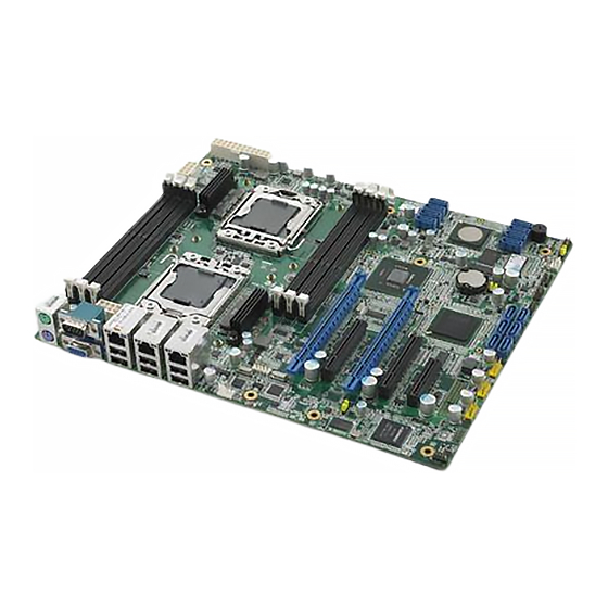
- Page 1 User Manual ASMB-310IR/310 Dual 1366 Socket CEB Server Board with 2 PCIe x16 Expansion Slots...
- Page 2 No part of this manual may be reproduced, copied, translated or transmitted in any form or by any means without the prior written permission of Advantech Co., Ltd. Information provided in this manual is intended to be accurate and reliable. How- ever, Advantech Co., Ltd.
- Page 3 SATA HDD P/N Description Manufacturer PN SEAGATE 500G 3.5" 96HD500G-ST-SG7K6 ST3500418AS SATA 7KRPM 16M(G) SEAGATE 1000G 3.5" 96HD1000G-ST-SG7K ST31000528AS SATA 7KRPM 32M(G) SAS HDD P/N Description Manufacturer PN Seagate 3.5" SAS 15K 96HD146G-SS-SG15K1 ST3146356SS 146G, dual ports ASMB-310IR/310 User Manual...
- Page 4 It should be free of marks and scratches and in per- fect working order upon receipt. As you unpack the ASMB-310IR, check it for signs of shipping damage. (For example, damaged box, scratches, dents, etc.) If it is dam- aged or it fails to meet the specifications, notify our service department or your local sales representative immediately.
-
Page 5: Table Of Contents
BIOS Setup ..................... 31 3.2.1 Main Menu .................. 31 3.2.2 Advanced BIOS Features Setup..........32 3.2.3 Advanced PCI/PnP Settings ............36 3.2.4 Boot Settings................37 3.2.5 Security Setting................39 3.2.6 Advanced Chipset Settings............39 3.2.7 Exit Option .................. 41 ASMB-310IR/310 User Manual... - Page 6 ASMB-310IR/310 User Manual...
-
Page 7: Chapter 1 Overview
Chapter Overview... -
Page 8: Introduction
High reliability and outstanding performance make the ASMB-310IR the ideal platform for industrial server/networking applications. By using the Intel E5520 chipset, the ASMB-310IR offers five PCIe slots; two PCIe x16 slots, two PCIe x8 slots, one PCIe x4 slot and a variety of features such as 6 onboard SATA II interfaces (bandwidth = 300 MB/s) with software for RAID 0, 1, 10 and 5 (Windows only);... -
Page 9: Features
SAS hard drive support: Embedded LSI 1068E SAS controller which can sup- port eight SAS/SATA HDD with software RAID 0,1,1E. IPMI 2.0 support: ASMB-310IR equip Aspeed 2050 BMC chip supports IPMI 2.0 (Intelligent Platform Management Interface 2.0) via dedicated LAN port. ... -
Page 10: Specifications
Intel 5520 IOH provide 36 lanes PCIe Gen-2 bus, used for PCIe Chipsets slots. ICH10R provide SATA, USB, Network, motherboard basic I/Os SAS LSI1068E (ASMB-310IR SKU Only) conntected to ICH10R PCI-e Gen1 x4 lanes 1x Intel 82574L Gigabit Ethernet Controller connected to ICH10R PCIe-Gen-1 Lane ... - Page 11 Total of five fan headers supporting up to 5 fans Five 4-pin fan headers 4 x fans with tachometer status monitoring Thermal Control for 4 x fan connectors Monitoring for CPU *2 (PECI) Temperature Monitoring for System (SIO) ASMB-310IR/310 User Manual...
-
Page 12: Board Layout, Jumpers And Connectors
Non-operating Relative Humidity: 5 to 95% (non-condensing) Board Layout, Jumpers and Connectors Connectors on the ASMB-310IR motherboard link it to external devices such as hard disk drives and a keyboard. In addition, the board has a number of jumpers that are used to configure your system for your application. -
Page 13: Figure 1.2 Rear I/O
SSI EPS 12 V auxiliary power connector (for CPU0) and memory ATX_8P_P1 SSI EPS 12 V auxiliary power connector (for CPU1) and memory ATX_P24 SSI EPS 24-pin main power connector (for system) COM2 Serial port: RS-232 CPU0 Intel LGA1366 CPU0 socket CPU1 Intel LGA1366 CPU1 socket ASMB-310IR/310 User Manual... -
Page 14: Table 1.5: Onboard Led
Serial ATA3 hard drive connector SATA4 Serial ATA4 hard drive connector SATA5 Serial ATA5 hard drive connector SGPIOA1 GPIO connector for SAS0 ~ SAS3 (For ASMB-310IR only) SGPIOB1 GPIO connector for SAS4 ~ SAS7 (For ASMB-310IR only) SYSDFAN1 system fan connector (4-pin) SYSRFAN1... -
Page 15: Block Diagram
Console Intel Intel SPI ROM 82574L 82567LM SST25VF RJ45 CN Realtek GbE Controller 032B w/ IPMI 10/100/Giga 10/100/Giga RTL8201 32 Mbits Winbond W83627DHG (10/100) (Super I/O) RJ45 CN RJ45 CN LAN2 LAN1 KB & MS COM1 COM2 ASMB-310IR/310 User Manual... -
Page 16: System Memory
System Memory ASMB-310IR has six 240-pin memory sockets for DDR3 1066/1333 MHz memory modules with maximum capacity of 48 GB (Maximum 8 GB for each DIMM). ASMB-310IR supports registered DIMMs or unbuffered DIMM with ECC / Non-ECC memory module. Memory Installation Procedures To install DIMMs, first make sure the two handles of the DIMM socket are in the "open"... -
Page 17: Chapter 2 Connections
Chapter Connections... -
Page 18: Introduction
480 Mbps and fuse protection are supported. The USB interface can be disabled in the system BIOS setup. The ASMB-310IR & ASMB-310 are equipped with two high-performance 1000 Mbps Ethernet LANs. They are supported by all major network operating systems. The RJ- 45 jacks on the rear plate provide convenient 1000Base-T operation. -
Page 19: Vga Connector
VGA Connector The ASMB-310IR includes VGA interface that can drive conventional CRT and LCD displays. COM1_VGA ASMB-310IR/310 User Manual... -
Page 20: Serial Ports (Com1/Com2)
Serial Ports (COM1/COM2) The ASMB-310IR offers 2 serial ports (One on the rear panel and one onboard). COM1 COM2 COM2 ASMB-310IR/310 User Manual... -
Page 21: Ps2 Keyboard And Mouse Connectors (Kb1Ms)
PS2 Keyboard and Mouse Connectors (KB1MS) Two 6-pin mini-DIN connectors (KBMS1) on the rear panel of the motherboard pro- vide PS/2 keyboard and mouse connections. KB1 MS ASMB-310IR/310 User Manual... -
Page 22: Cpu Fan Connector (Cpu Fan0/Cpu Fan1)
CPU Fan Connector (CPU FAN0/CPU FAN1) CPUFAN1 CPUFAN0 ASMB-310IR/310 User Manual... -
Page 23: System Fan Connector (Sys Dfan1/Ufan1/Rfan1)
System FAN Connector (SYS DFAN1/UFAN1/ RFAN1) SYSUFAN1 SYSDFAN1 SYSRFAN1 ASMB-310IR/310 User Manual... -
Page 24: Front Panel Connector (Fpph1)
Front Panel Connector (FPPH1) FPPPH1 ASMB-310IR/310 User Manual... -
Page 25: Sgpio (Sgpioa1/Sgpiob1)
SGPIO (SGPIOA1/SGPIOB1) SGPIOB1 SGPIOA1 SGPIOA1 SGPIOB1 SGPIOA1 SGPIOB1 SIOCLKA SIOCLKB SIOENDA SIOENDB SIOENDA SIOENDB SIODINA SIODINB ASMB-310IR/310 User Manual... -
Page 26: Front Panel Lan Indicator Connector (Lanled1)
2.10 Front Panel LAN Indicator Connector (LANLED1) LANLED1 2 4 6 8 10 1 3 5 7 9 LANLED1 LAN1_LED0_ACT LAN2_LED1_ACT VCC3_LAN1LED VCC3_LAN2LED LAN1_LED1_1000M LAN2_LED2_1000 LAN1_LED2_100M LAN2_LED0_100 VCC3 ASMB-310IR/310 User Manual... -
Page 27: Serial Ata Interface (Sata0 ~ 5)
2.11 Serial ATA Interface (SATA0 ~ 5) ASMB-310IR features six high performance serial ATA interface (up to 300 MB/s) which eases cabling to hard drives with thin and long cables. SATA3 SATA0 SATA4 SATA1 SATA2 SATA5 ASMB-310IR/310 User Manual... -
Page 28: Pcie X16 Expansion Slot (Pciex16_1/Pciex16_3)
2.12 PCIe x16 Expansion Slot (PCIEX16_1/ PCIEX16_3) The ASMB-310IR provides two PCIe x16 slots. PCIe x16 Note! PCIe x16 can only run x8 link while next PCIe x8 is occupied. ASMB-310IR/310 User Manual... -
Page 29: Pcie X4 Expansion Slot (Pciex4_5/Pciex4_6)
2.13 PCIe x4 Expansion Slot (PCIEX4_5/PCIEX4_6) The ASMB-310IR provides One PCIe x4 slot. (ASMB-310 provides two PCIe x4 slots) This slot only available in ASMB-310 SKU. PCIe x4 ASMB-310IR/310 User Manual... -
Page 30: Pcie X8 Expansion Slot (Pciex8_2/Pciex8_4)
2.14 PCIe x8 Expansion Slot (PCIEX8_2/PCIEX8_4) The ASMB-310IR provides two PCIe x8 slots. PCIe x8 ASMB-310IR/310 User Manual... -
Page 31: Series Attached Scsi Interface (Sas0 ~ 7)
2.15 Series Attached SCSI Interface (SAS0 ~ 7) SAS0 SAS4 SAS1 SAS5 SAS2 SAS6 SAS3 SAS7 ASMB-310IR/310 User Manual... -
Page 32: Auxiliary Power Connector (Atx_8P_Pq/Atx_8P_P1/Atx_P24)
2.16 Auxiliary Power Connector (ATX_8P_PQ/ ATX_8P_P1/ATX_P24) 8P_P1 8P_P0 ATX_P24 ASMB-310IR/310 User Manual... -
Page 33: Hd Audio Interface Connector (Hdaud1)
2.17 HD Audio Interface Connector (HDAUD1) HDAUD1 HDAUD1 +5 V_AUD ACZ_SYNC ACZ_BITCLK ACZ_SDOUT ACZ_SDIN0 ACZ_SDIN1 ACZ_RST# +AC_12V ASMB-310IR/310 User Manual... -
Page 34: Lpu Connector (Lpu2)
2.18 LPU connector (LPU2) LPU2 9 7 5 3 1 10 8 6 4 2 LPC2 CLK_33M_PORT80_CN LPC_LAD1 PLTRST_LPCP80 LPC_LAD0 LPC_LFRAME +3.3 V LPC_LAD3 LPC_LAD2 ASMB-310IR/310 User Manual... -
Page 35: Chapter 3 Ami Bios
Chapter AMI BIOS... -
Page 36: Introduction
The Setup program uses a number of menus for making changes and turning the special features on or off. This chapter describes the basic navigation of the ASMB-310IR setup screens. AMI's BIOS ROM has a built-in Setup program that allows users to modify the basic system configuration. -
Page 37: Bios Setup
Date using the <Arrow> keys. Enter new values through the keyboard. Press the <Tab> key or the <Arrow> keys to move between fields. The date must be entered in MM/DD/YY format. The time must be entered in HH:MM:SS format. ASMB-310IR/310 User Manual... -
Page 38: Advanced Bios Features Setup
3.2.2 Advanced BIOS Features Setup Select the Advanced tab from the ASMB-310IR setup screen to enter the Advanced BIOS setup screen. You can select any of the items in the left frame of the screen, such as CPU configuration, to go to the sub menu for that item. You can display an Advanced BIOS Setup option by highlighting it using the <Arrow>... - Page 39 A20M This makes legacy OS compatible with some APs. Intel® SpeedStep® tech When set to disabled, the CPU runs at its default speed, when set to enabled, the CPU speed is controlled by the operating system. ASMB-310IR/310 User Manual...
- Page 40 CPU speed and voltage will be reduced during system halt state to save power consumption. You may choose to enable or disable it. 3.2.2.2 IDE Configuration 3.2.2.3 Intel VT-d Setting Intel VT-d Configuration To support Intel chipset virtualization technology for directed I/O. ASMB-310IR/310 User Manual...
- Page 41 Enable/Disable the Chassis Intrusion monitoring function. When the case is opened, the buzzer beeps. 3.2.2.5 Super I/O Configuration Serial Port1 Address This option configures serial port 1 base addresses. Serial Port2 Address This option configures serial port 2 base addresses. ASMB-310IR/310 User Manual...
-
Page 42: Advanced Pci/Pnp Settings
3.2.3 Advanced PCI/PnP Settings Select the PCI/PnP tab from the ASMB-310IR setup screen to enter the Plug and Play BIOS Setup screen. You can display a Plug and Play BIOS Setup option by highlighting it using the <Arrow> keys. All Plug and Play BIOS Setup options are described in this section. -
Page 43: Boot Settings
Enabled, an OEM Logo is shown instead of POST messages. AddOn ROM Display Mode Set display mode for option ROM. Interrupt 19 Capture Some add-on cards' option ROMs need Interrupt 19, this is to enable or disable supporting this kind of add-on cards. ASMB-310IR/310 User Manual... - Page 44 Boots Graphic Adapter Priority ASMB-310IR/310 User Manual...
-
Page 45: Security Setting
3.2.5 Security Setting Select Security Setup from the ASMB-310IR Setup main BIOS setup menu. All Secu- rity Setup options, such as password protection and virus protection are described in this section. To access the sub menu for the following items, select the item and press <Enter>:... - Page 46 PCI-E port assign method defaults as “Auto”. When inserting a riser card into PCI-E x16 Slot 1, and it fails to recognize the add-on card of the riser card, plase change the default setting to x8x8x8x8 manually. ASMB-310IR/310 User Manual...
-
Page 47: Exit Option
BIOS setup and reboot the computer so the new system configuration parameters can take effect. Select Save Changes and Exit from the Exit menu and press <Enter>. The fol- lowing message appears: Save Configuration Changes and Exit Now? [Ok] [Cancel] Select Ok or Cancel. ASMB-310IR/310 User Manual... - Page 48 3.2.7.4 Load Optimal Defaults The ASMB-310IR automatically configures all setup items to optimal settings when you select this option. Optimal Defaults are designed for maximum system perfor- mance, but may not work best for all computer applications. In particular, do not use the Optimal Defaults if your computer is experiencing system configuration problems.
- Page 49 ASMB-310IR/310 User Manual...
- Page 50 No part of this publication may be reproduced in any form or by any means, electronic, photocopying, recording or otherwise, without prior written permis- sion of the publisher. All brand and product names are trademarks or registered trademarks of their respective companies. © Advantech Co., Ltd. 2011...
Need help?
Do you have a question about the ASMB-310IR and is the answer not in the manual?
Questions and answers