
Related Manuals for Advantech ASMB-260T2-22A1


Summary of Contents for Advantech ASMB-260T2-22A1
- Page 1 User Manual ASMB-260 Series Intel® Atom™ C3000 Mini-ITX Server Board with 4 DDR4 DIMM, 1 PCIe x4 Slot (Gen 3.0), 8 SATA III, IPMI...
- Page 2 No part of this manual may be reproduced, copied, translated or transmitted in any form or by any means without the prior written permission of Advantech Co., Ltd. Information provided in this manual is intended to be accurate and reliable. How- ever, Advantech Co., Ltd.
- Page 3 Advantech has come to be known. Your satisfaction is our primary concern. Here is a guide to Advantech’s cus- tomer services.
- Page 4 Also notify the carrier. Retain the shipping carton and packing material for inspection by the carrier. After inspection, we will make arrange- ments to repair or replace the unit. Order Information Part Number 10GbE SATA IPMI ASMB-260T2-22A1 C3758 ASMB-260I-22A1 C3758 ASMB-260I-21A1 C3558 ASMB-260 User Manual...
-
Page 5: Table Of Contents
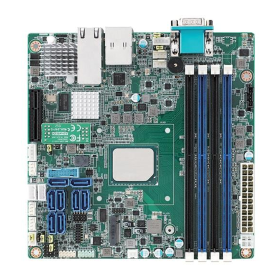
Table 1.1: Specifications ............. 3 Board Layout, Jumpers and Connectors........... 4 Figure 1.1 Board Layout .............. 4 Figure 1.2 Rear I/O of ASMB-260T2-22A1......... 5 Figure 1.3 Rear I/O of ASMB-260I-22A1/ASMB-260I-21A1 ..5 Table 1.2: Onboard LAN LED Color Definition ......5 Table 1.3: Jumpers.............. - Page 6 3.2.5 Security..................49 3.2.6 Boot .................... 50 3.2.7 Save & Exit ................. 51 Chapter Chipset Software Installation Utility Before Beginning ..................54 Introduction ..................... 54 Windows Series Driver Setup ..............55 Chapter Graphic Setup ........57 Introduction ..................... 58 Windows Series Driver Setup ..............58 Chapter LAN, USB 3.0 and RSTe RAID..
-
Page 7: Chapter 1 Overview
Chapter Overview... -
Page 8: Introduction
Introduction The ASMB-260 serverboard is the most advanced Intel ATOM C3000 series server board for storage, networking or micro-server applications. ASMB-260 is able to sup- port DDR4 ECC-REG 1866/2133/2400 MHz memory up to 128GB by 4 x DDR4 DIMMs. ASMB-260 provides one PCIex4 Gen3.0 high speed. In addition, the full ASMB-260 SKU has dual 10GbE Ethernet LAN ports with one GbE that eliminates network bottlenecks. -
Page 9: Specifications
Specifications Table 1.1: Specifications Processor Single Intel ATOM C3000 series SoC up to 16 cores Supports the TDP of processor up to 32 W System Memory Supports DDR4 memory bus Total 4 memory slots provided (When ASMB-260 is paired with Soc of C3338 and 3308, there are only 2 memory slots (DIMMA1 and DIMMA2) is available.) Memory Capacity... -
Page 10: Board Layout, Jumpers And Connectors
Table 1.1: Specifications PC Health Monitoring Voltage Monitors for CPU Cores, +3.3V, +5V, +12V, +5V Standby, VBAT One 4-pin header for CPU cooler and four 4-pin headers for sys- tem fans All fans with tachometer status monitoring Thermal control for all fan connectors ... -
Page 11: Figure 1.2 Rear I/O Of Asmb-260T2-22A1
Figure 1.2 Rear I/O of ASMB-260T2-22A1 Figure 1.3 Rear I/O of ASMB-260I-22A1/ASMB-260I-21A1 Note! LAN1 and LAN3 are share-NIC ports for IPMI remote management function. Table 1.2: Onboard LAN LED Color Definition 10M/100M/1G & 10G bps LAN Link/Activity LED Scheme LAN2 & LAN3 (10G) -
Page 12: Table 1.3: Jumpers
Table 1.3: Jumpers Label Function Default JCMOS1 CMOS Clear JME1 ME update Keep CMOS data/Disable ME update Clear CMOS data/Enable ME update Table 1.4: Connectors Label Function ATXPWR1 ATX 24 Pin main power connector 4-pin 12V DC Power Connector (to provide alternative power to ATXPWR2 embedded devices when the 24-pin ATX power is not in use) SATA0-SATA7... -
Page 13: Block Diagram
Table 1.5: Onboard LED Blinking (Green): LED2 BMC heartbeat LED Controller is working normally Block Diagram Channel A CPU Power ECC DDR4 U-DIMM or R-DIMM 1866/2133/2400/2666 MHz VR13 Channel B ECC DDR4 U-DIMM or R-DIMM PCIe x4 Slot 1866/2133/2400/2666 MHz RJ45 Intel X557-AT2 KR TX/RX diff. - Page 14 ASMB-260 User Manual...
-
Page 15: Chapter 2 Connections
Chapter Connections... -
Page 16: Introduction
Introduction You can access most of the connectors from the top of the board as it is being installed in the chassis. If you have a number of cards installed, you may need to par- tially remove a card to make all the connections. USB Ports (USB1_2, USB3_4) The two USB 3.0 ports on the rear plate and two USB3.0 on-board ports could reach transmission rates up to 5Gbps. -
Page 17: Lan Ports (Lan1~Lan3)
LAN Ports (LAN1~LAN3) The ASMB-260 is equipped with two 10GbE (LAN2, 3) and one GbE LAN (LAN1) ports. One of the 10 GbE LAN (LAN3) and GbE (LAN1) may be used as IPMI LAN as well for system management. They are all with RJ-45 jacks and supported by all major network operating systems. -
Page 18: Serial Ports (Com1~2)
Serial Ports (COM1~2) The ASMB-260 offers one serial port COM1 on the rear IO and one onboard pin header for COM2. CPU Fan Connector (CPUFAN0) If a fan needs to be used, this connector supports cooling fans that draw up to 1.5A (18W). -
Page 19: System Fan Connector (Sysfan0~3)
System Fan Connector (SYSFAN0~3) SYSFAN0~4 Front Panel Connector (JFP1~3) There are several external switches and LEDs to monitor and control the ASMB-260. ASMB-260 User Manual... -
Page 20: Power Led (Jfp3)
2.8.1 Power LED (JFP3) JFP3 pin 1 and pin 3 are for the power LED. Refer to Appendix B for detailed infor- mation on the pin assignments. If an ATX power supply is used, the system’s power LED status will be as indicated as follows. Table 2.1: ATX Power Supply LED Status ACPI Power Mode LED (ATX power) -
Page 21: Dc Sata Power Connector (Sata_Pwr1 And Sata_Pwr2)
2.8.5 DC SATA Power Connector (SATA_PWR1 and SATA_PWR2) To provide DC power for SATA drive. 2.8.6 Case Open (JCASE1) A chassis intrusion header is located at JCASE1 on the motherboard. Attach the appropriate cable from the chassis to be informed of a chassis intrusion when the chassis is opened. -
Page 22: Front Panel Lan Indicator Connector (Lanled1)
Front Panel LAN Indicator Connector (LANLED1) LANLED1 2.10 SATA and M.2 Connector (SATA0~7, M2_2242) ASMB-260 features eight serial ATA III interfaces (up to 600 MB/s) which eases cabling to hard drives. The M.2 2242 connector can support SATA only. The connectors of SATA PWR1 and SATA_PWR2 provide SATA drive power from ASMB-260 when power source is from ATXPWR2 (DC 12V). -
Page 23: Pcie Expansion Slots
2.11 PCIe Expansion Slots The ASMB-260 provides one expansion slot with PCIe x4 link for PCIe x4 cards only. ASMB-260 User Manual... -
Page 24: Auxiliary Power Connector (Atxpwr1/Atxpwr2)
2.12 Auxiliary Power Connector (ATXPWR1/ ATXPWR2) Note! Please use a power supply which is of SSI type; minimum output should be at least 180 W. ATXPWR1: Auxiliary Power Connector ATXPWR2: Power connector for DC 12V in only. Either ATXPWR1 or ATXPWE2 sockets should be connected with power supply, otherwise ASMB-260 will not boot up normally. -
Page 25: Lpc Connector (Lpc1)
2.13 LPC Connector (LPC1) LPC connector on ASMB-260 is for debug purpose only. All LPC modules are not supported by LPC connector of ASMB-260. LPC1 2.14 Clear CMOS Connector (JCMOS1, JME1) Setting jumper from pin 1-2 to pin 2-3, then back to pin 1-2 to reset CMOS data. JME1 JCMOS1 ASMB-260 User Manual... -
Page 26: Pmbus Connector (Pmbus1)
2.15 PMBUS Connector (PMBUS1) PMBUS1 2.16 IPMI Module Connector (BMC_CN1) This connector only fits to Advantech's BMC Module that will exist in ASMB-260 I & T2 SKUs for enabling the IPMI function. BMC_CN1 ASMB-260 User Manual... -
Page 27: Gpio Connector (Gpio1)
2.17 GPIO Connector (GPIO1) GPIO1 ASMB-260 User Manual... - Page 28 ASMB-260 User Manual...
-
Page 29: Chapter 3 Ami Bios
Chapter AMI BIOS... -
Page 30: Introduction
Introduction With the AMI BIOS Setup program, you can modify BIOS settings and control the special features of your computer. The Setup program uses a number of menus for making changes and turning the special features on or off. This chapter describes the basic navigation of the ASMB-260 setup screens. -
Page 31: Bios Setup
BIOS Setup 3.2.1 Main Menu Press Del during bootup to enter AMI BIOS CMOS Setup Utility; the Main Menu will appear on the screen. Use arrow keys to select among the items and press Enter to accept or enter the sub-menu. The Main BIOS setup screen has two main frames. -
Page 32: Advanced Bios Features Setup
3.2.2 Advanced BIOS Features Setup Select the Advanced tab from the ASMB-260 setup screen to enter the Advanced BIOS setup screen. You can select any of the items in the left frame of the screen, such as CPU configuration, to go to the sub menu for that item. You can display an Advanced BIOS Setup option by highlighting it using the Arrow keys. - Page 33 Enable or disable BIOS support for security device. Note! ASMB-260 doesn't support Advantech LPC TPM module. The TPM fea- ture is enabled by BOM changed as a T-part number. If you have an inquiry about TPM, contact Advantech distributor or sales representa- tive.
- Page 34 3.2.2.3 AST2500 Super IO Configuration Serial Port 1 and Port 2 Configuration – Serial Port Enable or disable serial port 1. ASMB-260 User Manual...
- Page 35 3.2.2.4 AST2500 Function Case Open Warning Enable or disable the chassis intrusion monitoring function. When enabled and the case is opened, the warning message will show in the POST screen. Wake On Ring Enable or disable wake on ring feature. Watch Dog Timer ...
- Page 36 3.2.2.5 AST2500 HW Monitor Displays HW monitor information on this page. 3.2.2.6 RTC Wake Setting RTC Wake system from S5 Enable or disable system wake on alarm event. ASMB-260 User Manual...
- Page 37 3.2.2.7 Serial Port Console Redirection COM1/COM2 Console Redirection Settings COM1 Console Redirection Settings. ASMB-260 User Manual...
- Page 38 – Terminal Type Select a terminal type to be used for console redirection. Options available: VT100/VT100+/ANSI /VT-UTF8. – Bits Per Second Select the baud rate for console redirection. Options available: 9600/19200/57600/115200. – Data Bits Options available: 7/8 – Parity A parity bit can be sent with the data bits to detect some transmission errors. Even: parity bit is 0 if the number of 1's in the data bits is even.
- Page 39 – VT-UTF8 Combo Key Support Enable VT-UTF8 combination key support for ANSI/VT100 terminals. – Recorder Mode When this mode enabled, only text will be send. This is to capture Terminal data. Options available: Enabled/Disabled. – Resolution 100x31 Enable or disable extended terminal resolution. –...
- Page 40 Console Redirection Settings – Out-of-Band Mgmt Port To select the com port user would like to set for having console redirection feature. – Terminal Type Set as "VT100", "VT100+", "VT-UTF8", or "ANSI". "VT-UTF8" is the default setting. – Bits Per Second To select serial port transmission.
- Page 41 3.2.2.8 PCI Subsystem Settings Above 4G Decoding Enable or disable 64-bit capability. Devices to be decoded in above 4G address space (only if the system supports 64-bit PCI decoding). Note! Some graphic or GPU cards need to enable 4G Decoding. ASMB-260 User Manual...
- Page 42 3.2.2.9 CSM Configuration CSM Support Enable or disable UEFI CSM (Compatibility Support Module) to support a leg- acy PC boot process. GateA20 Active This item is useful when RT code is executed above 1MB. When it's set as Upon Request, GA20 can be disabled using BIOS services.
- Page 43 Option ROM Messages Force BIOS or keep current sets the display mode for Option ROM. Boot option filter Change UEFI/legacy ROM priority for boot option. ASMB-260 User Manual...
- Page 44 Network Controls the execution of UEFI and legacy PXE OpROM. Storage Control the execution of UEFI and legacy storage OpROM. ASMB-260 User Manual...
- Page 45 3.2.2.10 USB Configuration Legacy USB Support This is for supporting USB device under a legacy OS such as DOS. When choosing Auto, the system will automatically detect if any USB device is plugged into the computer and enable USB legacy mode when a USB device is plugged, or disable USB legacy mode when no USB device is attached.
- Page 46 Device Reset Time-out Selects the USB device reset time-out value. [10,20,30,40 sec] ASMB-260 User Manual...
- Page 47 Device Power-up Delay This item appears only when device power-up delay item is set to [manual]. Mass Storage Devices Default is Auto to enumerate mass storage devices according to media format. ASMB-260 User Manual...
-
Page 48: Intel Rc Setup
3.2.3 Intel RC Setup 3.2.3.1 Processor Configuration Processor Configuration Option to change the processor settings – EIST (GV3) Enable or disable EIST (GV3) ASMB-260 User Manual... - Page 49 – Turbo Enable or disable CPU Turbo capability. – CPU C State Enable or disable Cx state of the CPU. It takes effect after reboot. – Execute Disable Bit Enable or disable Execute Disable Bit. When disables, forces the XD feature flag to always return 0.
- Page 50 Server ME Configuration This item is to set up server ME technology parameters – Altitude The altitude of the platform location above the see level, expressed in meters. The hex number is decoded as 2’s complement signed integer. Pro- vide the 80000000 value if the altitude in unknown.
- Page 51 South Bridge Chipset Configuration This item is to set up south bridge parameters. – State After G3 To set up what state to go to when power is re-applied after a power failure (G3 state). – LAN1 I210 Controller ASMB-260 User Manual...
-
Page 52: Server Management
Enable or disable LAN1 controller. – LAN1 I210 PXE OpROM Enable or disable LAN1 PXE boot option feature – LAN2&LAN3 X557 Controller Enable or disableLAN2&LAN2 controller. – LAN2 X557 PXE OpROM Enable or disable LAN2 PXE boot option feature – LAN3 X557 PXE OpROM Enable or disable LAN3 PXE boot option feature 3.2.4... - Page 53 3.2.4.1 System Event Log SEL Components Enable or disable all features of system event logging during boot. Erase SEL Choose options for erasing SEL. When SEL is Full Choose options for reactions to a full SEL. Log EFI Status Codes Disable the logging of EFI status codes, log only error codes or only progress codes or both.
- Page 54 3.2.4.2 BMC Self Test Log Erase Log Erase log options. When Log is Full Select the action to be taken when log is full. 3.2.4.3 BMC Network Configuration ASMB-260 User Manual...
-
Page 55: Security
Configuration Address Source Select to configure LAN channel parameters statically or dynamically (by BMC). Unspecified option will not modify any BMC network parameters during BIOS phase. 3.2.5 Security ASMB-260 User Manual... -
Page 56: Boot
Note! With AC power & Battery. Short CMOS1 Jumper: Date/Time & Password: Keep Setting: reset to default AC power and CMOS battery are removed. Short CMOS1 Jumper: Date/Time: reset to default Password: Keep Setting: reset to default 3.2.6 Boot Setup Prompt Timeout Number of seconds to wait for setup activation key. -
Page 57: Save & Exit
3.2.7 Save & Exit Save Changes and Exit Exit system setup after saving the changes. Discard Changes and Exit Exit system setup without saving any changes. Save Changes and Reset Reset the system after saving changes. Discard Changes and Reset Reset system setup without saving any changes. - Page 58 ASMB-260 User Manual...
- Page 59 Chapter Chipset Software Installation Utility...
-
Page 60: Before Beginning
Before Beginning To facilitate the installation of the enhanced display drivers and utility software, read the instructions in this chapter carefully. The drivers for the ASMB-260 are located on the software installation CD. Before beginning, it is important to note that most display drivers need to have the relevant software application already installed on the system prior to installing the enhanced display drivers. -
Page 61: Windows Series Driver Setup
Windows Series Driver Setup Insert the driver CD into your system's CD-ROM drive. When the folder is displayed, move the mouse cursor over the folder "01_Chipset". Find the executable in this folder, click to install the driver. ASMB-260 User Manual... - Page 62 ASMB-260 User Manual...
-
Page 63: Chapter 5 Graphic Setup
Chapter Graphic Setup... -
Page 64: Introduction
Introduction Install the ASPEED VGA driver to enable this function, which includes the following features: 32-bit 2D graphics engine on board for normal use. 64 MB RAM for this chip, the highest resolution is 1920x1200. Windows Series Driver Setup Insert the driver CD into your system's CD-ROM drive. - Page 65 Chapter LAN, USB 3.0 and RSTe RAID...
-
Page 66: Lan Configuration
LAN Configuration 6.1.1 Introduction The ASMB-260 has one Gigabit Ethernet LAN connections via dedicated PCI Express x1 lanes: GbE LAN1 - Intel I210; two 10G Base-T LAN connectors LAN2 and LAN3 - Intel X557 PHY. They eliminate bottlenecks in network data flow when incorporating Gigabit Ethernet at 10Gbps. - Page 67 Appendix I/O Pin Assignments...
-
Page 68: A.1 Usb3.0 Header (Usb3_4)
USB3.0 Header (USB3_4) Table A.1: USB Header (USB3_4) Signal Signal +5 V USB4_RX_DN2 USB4_RX_DP2 USB4_TX_DN2 USB4_TX_DP2 USB3_N2 USB3_P2 NC (reserved for OC pin) USB3_P3 USB3_N3 USB4_TX_DP3 USB4_TX_DN3 USB4_RX_DP3 USB4_RX_DN3 +5 V VGA Connector (VGA1) Table A.2: VGA Connector (VGA1) Signal Signal GREEN BLUE... -
Page 69: A.3 Rs-232 Interface (Com2)
RS-232 Interface (COM2) Table A.3: RS-232 Connector (COM2) Signal RXD# TXD# System & CPU Fan Power Connector (SYSFAN0~3, CPUFAN0) Table A.4: CPU FAN Connector (CPUFAN0) CPUFAN0 +12V CPU_TACH CPU_PWM Table A.5: SYS FAN Connector (SYSFAN0~4) SYS FAN0 SYS FAN1 SYS FAN2 SYSFAN3 +12V +12V... -
Page 70: A.5 Power Led (Jfp3)
Power LED (JFP3) Table A.6: Power LED Connector (JFP3) Function LED power (3.3 V) LED power Keylock Ground External Speaker Connector (JFP2) 7 10 Table A.7: External Speaker Connector (JFP2) Function SPK+ SPK- Reset Connector (JFP1) 9 12 Table A.8: Reset Connector (JFP1) Signal RESET ASMB-260 User Manual... -
Page 71: A.8 Hdd Led Connector (Jfp2)
HDD LED Connector (JFP2) Table A.9: HDD LED Connector (JFP2) Signal HDD_LED+ HDD_LED- ATX Soft Power Switch (JFP1) Table A.10: ATX Soft Power Switch (JFP1) Signal PWR-BTN A.10 LAN Ports (LAN1~3) Table A.11: LAN RJ-45 Port (LAN1, LAN2_3) Signal Signal MID0+ MID2+ MID0-... -
Page 72: A.11 Case Open Connector (Jcase1)
A.11 Case Open Connector (JCASE1) Table A.12: Case Open Connector (JFP1) Signal CASEOP A.12 Front Panel LAN LED Connector (LANLED1) Table A.13: LAN LED Connector (LANLED1) Signal Signal LAN1_ACT# LAN2_ACT# +V3.3_AUX +V3.3_AUX LAN3_ACT# LAN4_ACT# +V3.3_AUX A.13 LPC Connector (LPC1) Table A.14: LPC Connector (LPC1) Signal Signal CLK_24M_LPCCN... -
Page 73: A.14 Clear Cmos Connector (Jcmos1, Jme1)
A.14 Clear CMOS Connector (JCMOS1, JME1) Table A.15: Clear CMOS Connector (JCMOS1, JME1) JP_CMOS JME1 Signal Signal RTC_RST_PCH# HDA_SDOUT_PCH +V3.3_SB A.15 PMBUS Connector (PMBUS1) Table A.16: PMBUS Connector (PMBUS1) Signal SMB_SCL_PM SMB_SDA_PM SMB_ALT_PM# +3.3V A.16 GPIO Connector (GPIO1) Table A.17: GPIO Connector (GPIO1) Signal Signal BMC_GPIO0... - Page 74 No part of this publication may be reproduced in any form or by any means, electronic, photocopying, recording or otherwise, without prior written permis- sion of the publisher. All brand and product names are trademarks or registered trademarks of their respective companies. © Advantech Co., Ltd. 2018...
Need help?
Do you have a question about the ASMB-260T2-22A1 and is the answer not in the manual?
Questions and answers