Sign In
Upload
Download
Table of Contents
Contents
Add to my manuals
Delete from my manuals
Share
URL of this page:
HTML Link:
Bookmark this page
Add
Manual will be automatically added to "My Manuals"
Print this page
×
Bookmark added
×
Added to my manuals
Manuals
Brands
Advantech Manuals
Server Board
ASMB-825I-00A1E
User manual
Advantech ASMB-825I-00A1E User Manual
Asmb-825 series dual lga 3647-p0 intel xeon server board with 6 ddr4, 4 pcie x16, 8 sata3, 6 usb3.0, dual 10gbe, ipmi
Hide thumbs
1
2
3
4
Table Of Contents
5
6
7
8
9
10
11
12
13
14
15
16
17
18
19
20
21
22
23
24
25
26
27
28
29
30
31
32
33
34
35
36
37
38
39
40
41
42
43
44
45
46
47
48
49
50
51
52
53
54
55
56
57
58
59
60
61
62
63
64
65
66
67
68
69
70
71
72
73
74
75
76
77
78
79
80
81
82
83
84
85
86
87
88
89
90
91
92
93
94
95
96
97
98
99
100
101
102
103
104
105
106
107
108
109
110
111
112
113
114
115
116
117
118
119
120
121
122
page
of
122
Go
/
122
Contents
Table of Contents
Bookmarks
Table of Contents
Declaration of Conformity
Table of Contents
Chapter 1 Overview
Introduction
Features
Specifications
Board Layout, Jumpers and Connectors
Table 1.2: Onboard LAN LED Color Definition
Table 1.4: Connectors
Block Diagram
System Memory
Table 1.5: Onboard LED
Memory Installation
Processor Installation
Chapter 2 Connections
Introduction
USB Ports (USB1~11)
LAN Ports (LAN1_2, LAN3_4)
VGA Connector (VGA1)
Serial Ports (COM1~2)
PS2 Keyboard and Mouse Connectors (KBMS2)
CPU Fan Connector (CPUFAN0~1)
System Fan Connector (SYSFAN0~4)
Front Panel Connector (JFP1)
Power LED (JFP3)
External Speaker (JFP2 Pins 1, 4, 7, 10)
HDD LED Connector (JFP1 Pins 2 & 5)
Reset Connector (JFP1 Pins 9 & 12)
Case Open (JCASE1)
Sata Sgpio (Sgpio1)
Front Panel LAN Indicator Connector (LANLED1)
SATA and M.2 Connector (SATA0~7, M2_2280)
Pcie Expansion Slots
Auxiliary Power Connector (ATXPWR1/ATX12V1/ATX12V2)
HD Audio Interface Connector (HDAUD1)
LPC Connector (LPC2)
Clear CMOS Connector (JCMOS1, JME1)
PMBUS Connector (PMBUS1)
Front Panel SMBUS Connector (SMBUS1)
IPMI Module Connector (BMC_CN1)
VOLT1 Connector (VOLT1)
GPIO Connector (GPIO1)
Intel Virtual RAID (VROC1)
Nvme RAID LED Control (PEHP1)
Chapter 3 AMI BIOS
Introduction
BIOS Setup
Main Menu
Advanced BIOS Features Setup
Platform Configuration
Socket Configuration
Server Management
Security
Boot
Save & Exit
Chapter 4 Chipset Software Installation Utility
Before Beginning
Introduction
Windows Series Driver Setup
Chapter 5 Graphic Setup
Introduction
Windows Series Driver Setup
Chapter 6 LAN, USB 3.0 and Rste RAID
LAN Configuration
Introduction
Windows Series Driver Setup
Usb 3.0
Windows Series Driver Setup
SATA & Pcie SSD RAID
Introduction
Appendix A Programming the Watchdog Timer
Watchdog Timer Overview
Programming the Watchdog Timer
Appendix B I/O Pin Assignments
USB2.0 Header (USB3_4, USB9_10)
USB3.0 Header (USB5_6, USB7_8)
VGA Connector (VGA1)
Interface (COM2)
External Keyboard Connector (KBMS2)
System & CPU Fan Power Connector (SYSFAN0~4, CPUFAN0~1)
Power LED (JFP3)
B.10 HDD LED Connector (JFP1)
B.13 USB & LAN Ports (USB1_2 and LAN1_2, LAN3_4)
B.15 Alarm Board Connector (VOLT1)
B.18 SATA SGPIO Connector (SGPIO1)
B.20 Clear CMOS Connector (JCMOS1, JME1)
Advertisement
Quick Links
Download this manual
User Manual
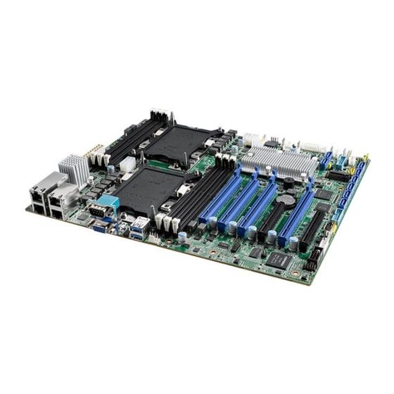
ASMB-825 Series
Dual LGA 3647-P0 Intel Xeon®
Server Board with 6 DDR4, 4
PCIe x16, 8 SATA3, 6 USB3.0,
Dual 10GbE, IPMI
Table of
Contents
Previous
Page
Next
Page
1
2
3
4
5
Advertisement
Table of Contents
Need help?
Do you have a question about the ASMB-825I-00A1E and is the answer not in the manual?
Ask a question
Questions and answers
Related Manuals for Advantech ASMB-825I-00A1E
Server Board Advantech ASMB-820I Startup Manual
Intel xeon e5-2400 series lga 1356 socket atx server board with 4 pcie & 2 pci expansion slots (3 pages)
Server Board Advantech ASMB-823I User Manual
Dual lga 2011-r3 intel xeon e5-2600v3 atx server board (110 pages)
Server Board Advantech ASMB-823I Startup Manual
Intel xeon e5-2600v3 series atx server board with ddr4, 4 pcie x16, 6 usb 3.0, 9 sata3 (3 pages)
Server Board Advantech ASMB-813I User Manual
Lga 2011-r3 intel xeon e5-2600v3 atx server board (100 pages)
Server Board Advantech ASMB-813I Series Startup Manual
Intel xeon e5-2600v3 series atx server board with 8 ddr4, 5 pcie x8, 6 usb 3.0, 8 sata3 (3 pages)
Server Board Advantech ASMB-825T2-00A1E User Manual
Asmb-825 series dual lga 3647-p0 intel xeon server board with 6 ddr4, 4 pcie x16, 8 sata3, 6 usb3.0, dual 10gbe, ipmi (122 pages)
Server Board Advantech ASMB-805 Startup Manual
Atx server board (3 pages)
Server Board Advantech ASMB-816 Series Startup Manual
Lga 4189 intel 3rd generation xeon scalable atx server board with 8 ddr4, 3 pcie x16, 8 sata3, 6 usb3.0, dual 10gbe, ipmi (3 pages)
Server Board Advantech ASMB-817 Series Startup Manual
Lga 4677 intel 4th generation xeon scalable atx server board with 8 ddr5, 3 pcie x16, 8 sata3, 4 usb3.2 gen1, dual 10gbe, ipmi (3 pages)
Server Board Advantech ASMB-825 Series User Manual
Dual lga 3647-p0 intel xeon server board with 6 ddr4, 4 pcie x16, 8 sata3.0, 6 usb3.0, dual 10gbe, ipmi (124 pages)
Server Board Advantech ASMB-922I User Manual
Intel e5-2600(v2) series dual processor eatx (104 pages)
Server Board Advantech ASMB-781 User Manual
Lga1155 intel xeon e3/ core i3 atx server board with 2 pcie x16 expansion slots (92 pages)
Server Board Advantech ASMB-784 User Manual
Lga 1150 intel xeon e3 v3 atx server board with 2 pcie x16 slots (x8 link) or 1 pcie x16 slot (x16 link), 3 pci, usb 3.0, pcie gen iii, quad/dual lans (112 pages)
Server Board Advantech ASMB-584 User Manual
Lga 1150 intel xeon e3 v3 micro atx server board with 2 pcie x16 slots (x8 link), 1 pcie x4, 1 pci, usb 3.0, pcie gen iii, dual lans (110 pages)
Server Board Advantech ASMB-260T2-22A1 User Manual
Asmb-260 series. intel atom c3000 mini-itx server board with 4 ddr4 dimm, 1 pcie x4 slot (gen 3.0), 8 sata iii, ipmi (74 pages)
Server Board Advantech ASMB-BMC User Manual
Bmc function application for single unit (50 pages)
This manual is also suitable for:
Asmb-825-00a1e
Asmb-825t2-00a1e
Table of Contents
Print
Rename the bookmark
Delete bookmark?
Delete from my manuals?
Login
Sign In
OR
Sign in with Facebook
Sign in with Google
Upload manual
Upload from disk
Upload from URL


Need help?
Do you have a question about the ASMB-825I-00A1E and is the answer not in the manual?
Questions and answers